1
Design Architect
Training Workbook
Software Version 8.5
Copyright 1991 - 1995 Mentor Graphics Corporation. All rights reserved.
Confidential. May be photocopied by licensed customers of
Mentor Graphics for internal business purposes only.
The software programs described in this document are confidential and proprietary products of Mentor
Graphics Corporation (Mentor Graphics) or its licensors. No part of this document may be photocopied,
reproduced or translated, or transferred, disclosed or otherwise provided to third parties, without the prior
written consent of Mentor Graphics.
The document is for informational and instructional purposes. Mentor Graphics reserves the right to make
changes in specifications and other information contained in this publication without prior notice, and the
reader should, in all cases, consult Mentor Graphics to determine whether any changes have been made.
The terms and conditions governing the sale and licensing of Mentor Graphics products are set forth in the
written contracts between Mentor Graphics and its customers. No representation or other affirmation of
fact contained in this publication shall be deemed to be a warranty or give rise to any liability of Mentor
Graphics whatsoever.
MENTOR GRAPHICS MAKES NO WARRANTY OF ANY KIND WITH REGARD TO THIS MATERIAL
INCLUDING, BUT NOT LIMITED TO, THE IMPLIED WARRANTIES OR MERCHANTABILITY AND
FITNESS FOR A PARTICULAR PURPOSE.
MENTOR GRAPHICS SHALL NOT BE LIABLE FOR ANY INCIDENTAL, INDIRECT, SPECIAL, OR
CONSEQUENTIAL DAMAGES WHATSOEVER (INCLUDING BUT NOT LIMITED TO LOST PROFITS)
ARISING OUT OF OR RELATED TO THIS PUBLICATION OR THE INFORMATION CONTAINED IN IT,
EVEN IF MENTOR GRAPHICS CORPORATION HAS BEEN ADVISED OF THE POSSIBILITY OF SUCH
DAMAGES.
RESTRICTED RIGHTS LEGEND Use, duplication, or disclosure by the Government is subject to
restrictions as set forth in the subdivision (c)(1)(ii) of the Rights in Technical Data and Computer Software
clause at DFARS 252.227-7013.
A complete list of trademark names appears in a separate “Trademark Information” document.
Mentor Graphics Corporation
8005 S.W. Boeckman Road, Wilsonville, Oregon 97070-7777.
This is an unpublished work of Mentor Graphics Corporation.
Table of Contents
TABLE OF CONTENTS
About This Training Workbook
Introduction
Installing the Training Data
Print Out the Lab Exercises
Course Overview
Training Workbook Goals
Timeline for Course Completion
Module 1
Design Architect
in the Framework Environment
Module 1 Overview
Lesson 1
The Electronic Design Data Model
Design Architect and the EDDM
Component Structure
(Conceptual View)
Component Structure
(Iconic View)
Component Within a Component
Design Viewpoint
(Conceptual View)
Lesson 2
Common Elements of the User Interface
Window Buttons and Navigator Controls
Menus and Mouse Buttons
Palettes
Softkeys
Command Window
Prompt Bars
Strokes
Quick Help on Strokes
Transcript Window
Design Architect Training Workbook, V8.5
xiii
xiii
xiii
xiii
xiv
xvi
xviii
1-1
1-2
1-3
1-4
1-6
1-8
1-10
1-12
1-15
1-16
1-18
1-20
1-22
1-24
1-26
1-28
1-30
1-32
iii
Table of Contents
TABLE OF CONTENTS [continued]
Session Setup
Lesson 3
Using Notepad to Create and Modify ASCII Files
Editing Files with Notepad
Lesson 4
Viewing and Searching Online Documentation
Online Help
Opening Online Documents
Searching and Traveling in Documents
Lesson 5
Using Design Manager to Copy Objects
Copying Objects in the Navigator Window
Soft Prefixes and Location Maps
Design Object References
Copying Design Objects
Moving and Deleting Design Objects
Checking and Changing Design References
Lab Exercises
Installing the Training Data
Print Out the Lab Exercises
Exercise 1: Copying the Training Data
Exercise 2: Using Notepad to Create and Modify ASCII Files
Exercise 3: Viewing and Searching Online Documents
Module 2
Creating a Schematic
Module 2 Overview
Lesson
Creating a Schematic
Invoking Design Architect
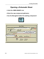
Opening a Schematic Sheet
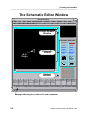
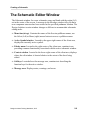
The Schematic Editor Window
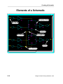
Elements of a Schematic
schematic_add_route Palette
iv
1-34
1-37
1-38
1-41
1-42
1-44
1-46
1-49
1-50
1-52
1-54
1-56
1-58
1-60
1-63
1-63
1-63
1-64
1-71
1-77
2-1
2-2
2-3
2-4
2-6
2-8
2-10
2-12
Design Architect Training Workbook, V8.5
Table of Contents
TABLE OF CONTENTS [continued]
Design Architect Strokes
Placing an Instance on a Sheet
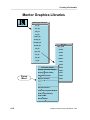
Mentor Graphics Libraries
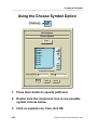
Using the Choose Symbol Option
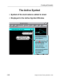
The Active Symbol
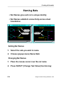
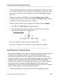
Adding Nets
Net Creation Process
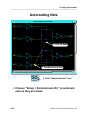
Autorouting Nets
Net Connection Rules
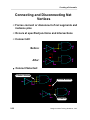
Connecting and Disconnecting Net Vertices
Naming Nets
Selection Concepts
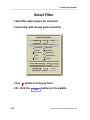
Select Filter
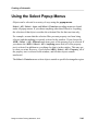
Using the Select Popup Menus
Manipulating Objects
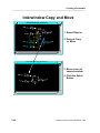
Interwindow Copy and Move
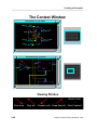
The Context Window
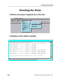
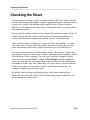
Checking the Sheet
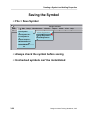
Saving the Sheet
Schematic Editor Window Status Line
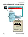
Using the Component Hierarchy Window
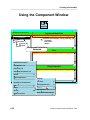
Using the Component Window
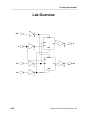
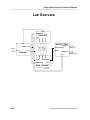
Lab Overview
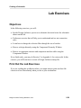
Lab Exercises
Objectives
Print Out the Lab Exercises
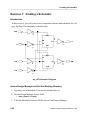
Exercise 1: Creating a Schematic
Exercise 2: Net Connection Rules
Exercise 3: Changing the Mouse Selection Filter
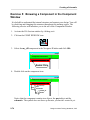
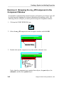
Exercise 4: Browsing a Component in the Component Hierarchy Window
Exercise 5: Browsing a Component in the Component Window
Design Architect Training Workbook, V8.5
2-14
2-16
2-18
2-20
2-22
2-24
2-26
2-28
2-30
2-32
2-34
2-36
2-38
2-40
2-42
2-44
2-46
2-48
2-50
2-52
2-54
2-56
2-58
2-59
2-59
2-59
2-60
2-70
2-71
2-73
2-74
v
Table of Contents
TABLE OF CONTENTS [continued]
Module 3
Creating a Symbol and Adding Properties
Module 3 Overview
Lesson 1
Creating a Symbol
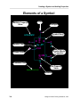
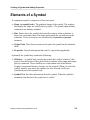
Elements of a Symbol
Opening a Symbol
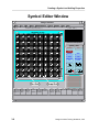
Symbol Editor Window
The symbol_draw Palette
Setting the Symbol Body Defaults
Adding Pins
Checking the Symbol
Changing Required Checks
Saving the Symbol
Lesson 2
Adding Properties
What is a Property?
Property Ownership
Property Types
Property Text Attributes
Symbol Property Text Switches
SLD Properties
Class Property Values
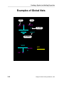
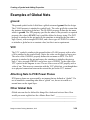
Examples of Global Nets
ground
VCC
Attaching Nets to PCB Power Planes
Other Global Nets
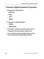
Common Digital Simulation Properties
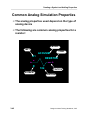
Common Analog Simulation Properties
Common PCB Layout Properties
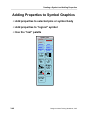
Adding Properties to Symbol Graphics
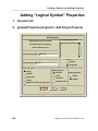
Adding “Logical Symbol” Properties
vi
3-1
3-2
3-3
3-4
3-6
3-8
3-10
3-12
3-14
3-16
3-18
3-20
3-23
3-24
3-26
3-28
3-30
3-32
3-34
3-36
3-38
3-39
3-39
3-39
3-39
3-40
3-42
3-44
3-46
3-48
Design Architect Training Workbook, V8.5
Table of Contents
TABLE OF CONTENTS [continued]
Reporting On and Deleting
“Logical Symbol” Properties
Changing Property Values
Selecting Properties
Changing Property Values
Changing Property Attributes
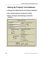
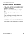
Setting Up Property Text Attributes
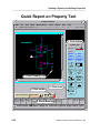
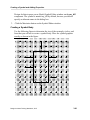
Quick Report on Property Text
Lab Exercises
Print Out the Lab Exercises
Exercise 1: Creating a Symbol
Exercise 2: Adding Properties to a Schematic
Exercise 3: Adding Properties to a Symbol
Exercise 4: Browsing the my_dff Component in the Component Window
Module 4
Additional Editing Features
Module 4 Overview
Lesson 1
Additional Editing Features
Setting Up the Page
Setting Up the Grids
Comment Text and Graphics
Add a Sheet Border
Creating a Bus/Bundle
Explicit Rippers
Manually Connecting a Wire to a Bus
Automatic Connection
Manual Connection
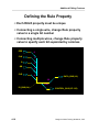
Defining the Rule Property
Setting up the Ripper
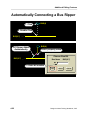
Automatically Connecting a Bus Ripper
The Sequence Text Function
Implicit Ripper
Design Architect Training Workbook, V8.5
3-50
3-52
3-53
3-53
3-53
3-54
3-56
3-59
3-59
3-60
3-70
3-75
3-82
4-1
4-2
4-3
4-4
4-6
4-8
4-10
4-12
4-14
4-16
4-17
4-17
4-18
4-20
4-22
4-24
4-26
vii
Table of Contents
TABLE OF CONTENTS [continued]
Frames
4-28
4-30
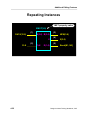
Frame Example
Repeating Instances
4-32
Selection Sets
4-34
Undo and Redo
4-36
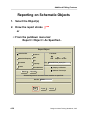
Reporting on Schematic Objects
4-38
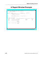
A Report Window Example
4-40
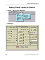
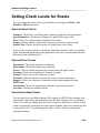
Setting Check Levels for Sheets
4-42
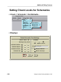
Setting Check Levels for Schematics
4-44
4-46
Lab Overview
Lab Exercises
4-47
Print Out the Lab Exercises
4-47
4-48
Exercise 1: Creating a Hierarchical Design
Exercise 2: Browsing the add_convert Component in the Component Hierarchy
Window
4-59
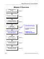
Module 5
Design Hierarchy and
Functional Blocks
5-1
Module 5 Overview
Lesson 1
Design Hierarchy and Functional Blocks
Hierarchical Design
Functional Blocks
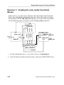
Creating Functional Blocks
Lesson 2
Updating Instances on a Schematic
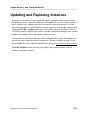
Updating and Replacing Instances
Symbol and Instance Properties
Attribute-Modified and Value-Modified Properties
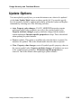
Update Options
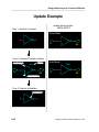
Update Example
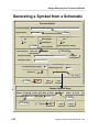
Generating a Symbol from a Schematic
viii
5-2
5-3
5-4
5-6
5-8
5-11
5-12
5-14
5-16
5-18
5-20
5-22
Design Architect Training Workbook, V8.5
Table of Contents
TABLE OF CONTENTS [continued]
Lab Overview
Lab Exercises
Print Out the Lab Exercises
Exercise 1: Creating the card_reader Functional Blocks
Exercise 2: Updating an Instance
Exercise 3: Generating a card_reader Symbol
5-24
5-25
5-25
5-26
5-34
5-35
Module 6
Working with Design Viewpoints and Back Annotation
6-1
Module 6 Overview
Lesson 1
Design Viewpoint Concepts
Design Viewpoint
(Conceptual View)
Multiple Views of a Source Design
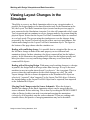
Viewing Layout Changes in the Simulator
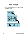
Design Viewpoints
(Iconic View)
Downstream Tools and Viewpoints
How Viewpoints are Created
Lesson 2
Using the Design Viewpoint Editor
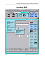
Invoking DVE
Opening a Design Viewpoint
Default Window Arrangement
Setting Up for a Downstream Application
The Default PCB Setup
Tasks that can only be done with DVE
Adding Parameters to the Viewpoint
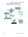
Search Path for Parameters
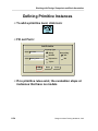
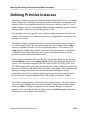
Defining Primitive Instances
Defining Visible Properties
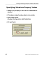
Specifying Substitute Property Values
Design Architect Training Workbook, V8.5
6-2
6-3
6-4
6-6
6-8
6-10
6-12
6-14
6-17
6-18
6-20
6-22
6-24
6-26
6-28
6-30
6-32
6-34
6-36
6-38
ix
Table of Contents
TABLE OF CONTENTS [continued]
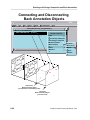
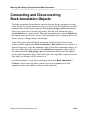
Connecting and Disconnecting
Back Annotation Objects
Other Tasks that may be done with DVE
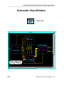
Schematic View Window
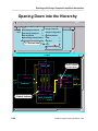
Opening Down into the Hierarchy
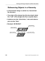
Referencing Objects in a Hierarchy
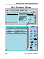
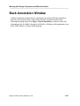
Back Annotation Window
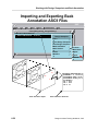
Importing and Exporting Back Annotation ASCII Files
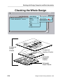
Checking the Whole Design
Latching a Viewpoint
Exporting a Design Configuration
Lesson 3
Using Design Architect to Edit and Merge Back Annotations
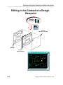
Editing in the Context of a Design Viewpoint
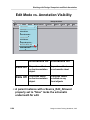
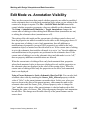
Edit Mode vs. Annotation Visibility
Annotations vs. Evaluations
Viewing and Editing Properties
Viewing and Editing Properties
(continued)
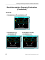
Back-Annotated Property Evaluation
Back-Annotation Property Evaluation
(Continued)
Expressions in Back Annotations
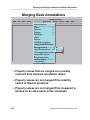
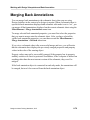
Merging Back Annotations
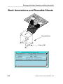
Back Annotations and Reusable Sheets
Lab Exercises
Print Out the Lab Exercises
Exercise 1: Creating a Simulation Viewpoint
Exercise 2: Creating a PCB Viewpoint
Exercise 3: Cross-connecting a Back Annotation Object
Exercise 4: Merging Annotations to the Source Sheet
x
6-40
6-42
6-44
6-46
6-48
6-50
6-52
6-54
6-56
6-58
6-61
6-62
6-64
6-66
6-68
6-70
6-72
6-74
6-76
6-78
6-80
6-83
6-83
6-84
6-95
6-100
6-103
Design Architect Training Workbook, V8.5
Table of Contents
TABLE OF CONTENTS [continued]
Module 7
Component Interfaces and Registration
7-1
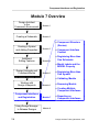
Module 7 Overview
7-2
Lesson
7-3
Component Structure
(Conceptual View)
7-4
Component Structure
7-6
(Iconic View)
Content of Component Interface
7-8
Model Labels and the MODEL Property
7-10
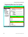
Creating More than One Schematic
7-12
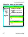
Registering More than One Schematic
7-14
Adding Labels to Models
7-16
7-18
Unregister Models
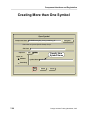
Creating More than One Symbol
7-20
Registering More than One Symbol
7-22
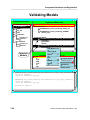
Validating Models
7-24
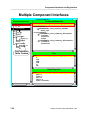
Multiple Component Interfaces
7-26
Reporting on Interfaces
7-28
CIB Commands
7-30
Lab Exercises
7-31
7-31
Print Out the Lab Exercises
Exercise 1: Creating a Second my_dff Schematic
7-32
Exercise 2: Reload the my_dff Instance on add_convert, then Switch Models to
7-39
schematic2
Exercise 3: Creating a Second add_convert Component Interface
7-40
Module 8
Using Design Manager to Release Designs
Module 8 Overview
Lesson 1
Design References
(Review)
Design Architect Training Workbook, V8.5
8-1
8-2
8-3
xi
Table of Contents
TABLE OF CONTENTS [continued]
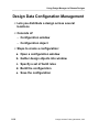
Design Object References
Copying Design Objects
Moving and Deleting Design Objects
Checking and Changing Design References
Lesson 2
Creating a Configuration
and Releasing a Design
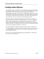
Configuration Objects
Design Data Configuration Management
Configuration Operations
Versions
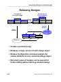
Releasing Designs
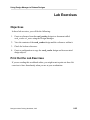
Lab Exercises
Objectives
Print Out the Lab Exercises
Exercise 1: Exploring References
Exercise 2: Verifying and Changing References
Exercise 3: Creating and Copying a Configuration
Appendix A
Customizing Exercises
8-13
8-14
8-16
8-18
8-20
8-22
8-25
8-25
8-25
8-26
8-29
8-31
A-1
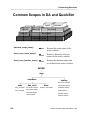
Common Scopes in DA and QuickSim
Command Window
Lab Exercises
Exercise 1: Creating a .startup file for BOLD Browser
Exercise 2: Creating a .startup file for da_session
Exercise 3: Add a Navigator Button to the Set Working Directory Form
Exercise 4: Customizing the “Modify Property” Stroke
Exercise 5: Add a “Zoom-to-Previous” Function Key
Exercise 6: Fix this Broken Design Database
xii
8-4
8-6
8-8
8-10
A-2
A-4
A-7
A-9
A-14
A-15
A-17
A-20
A-22
Design Architect Training Workbook, V8.5
About This Training Workbook
Introduction
About This Training Workbook
Introduction
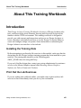
This Design Architect Training Workbook is for users of Design Architect who
have some knowledge about schematic drawing and electronic design and are
familiar with the UNIX environment. This training workbook is designed to
provide you with concepts and instructions on how to use Design Architect to
create schematics and symbols and how to use the Design Viewpoint Editor to
create and configure design viewpoints. Some instruction on customizing the
Design Architect user interface is also include.
Installing the Training Data
Before attempting to perform the lab exercises in this module, make sure that the
design data for this Design Architect training program has been installed on your
network. The training data should be at the following path:
$MGC_HOME/shared/training/da85nwp.
If you can’t find the design data, contact you system administrator for assistance
or refer to the Mentor Graphics manual titled Installing Mentor Graphics
Software for Falcon Framework Products.
Print Out the Lab Exercises
If you are reading this workbook online, you might want to print out these lab
exercises to have them handy when you are at your workstation.
Design Architect Training Workbook, V8.5
xiii
Introduction
About This Training Workbook
Course Overview
Design Architect
in the
Framework Environment
Creating a Schematic
Creating a Symbol
and Adding Properties
Additional
Editing Features
Design Hierarchy and
Functional Blocks
Working with
Design Viewpoints
Component Interfaces
and Registration
Using Design Manager
to Release Designs
xiv
Module 1
Module 2
Module 3
Module 4
Module 5
Module 6
Module 7
Module 8
Design Architect Training Workbook, V8.5
About This Training Workbook
Introduction
Course Overview
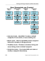
1. Design Architect and the Falcon Environment. Introduces the Electronic
Design Data Model (EDDM), explains common elements in the Falcon
Framework User Interface, covers how to reference and relocate design objects
and introduces the editors within Design Architect.
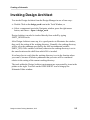
2. Creating a Schematic. Describes how to invoke the Schematic Editor and
create a schematic using the most efficient entry methods.
3. Creating a Symbol and Adding Properties. Describes how to create a symbol
for a new component and annotate the symbol and associated schematic with
common properties and property values.
4. Creating Design Hierarchy. Covers how to create layers of design hierarchy.
The more advanced editing features are also covered, such as: how to set the
pin and grid spacing, create buses and bus rippers, frames, selection sets, and
comment text and graphics.
5. Creating Functional Blocks. Shows how Design Architect supports top-down
design methodology by drawing functional blocks on a schematic sheet, then
converting the blocks into symbols and new components structures for lowerlevels of the design hierarchy.
6. Working with Design Viewpoints and Back Annotation. Covers design
viewpoints and back annotation in more detail. Explains how to create and
configure a viewpoint along with how to use Design Architect to selectively
merge back annotation information on to source sheets.
7. All about Component Interfaces and Registration. Explains the control center
for the component structure, the Component Interface, in more detail. This
module covers methods for registering and selecting from multiple functional
models and symbols in the same component structure, plus how different
functional models and symbols are selected for use through a labeling
mechanism.
8. Using Design Manager to Release Designs. Describes how to create
configurations of design objects and release whole designs to an achieve.
Design Architect Training Workbook, V8.5
xv
Introduction
About This Training Workbook
Training Workbook Goals
• Introduce Design Architect, the Electronic Design Data
Model (EDDM), and the Falcon Framework design
environment
• Use the Design Architect editors to create schematics and
symbols
• Create a design bottom-up with several levels of hierarchy
• Create a design top-down using functional blocks
• Create design viewpoints, then manage and selectively merge
back annotations to source sheets
• Use Design Manager to release whole designs to an achieve
xvi
Design Architect Training Workbook, V8.5
About This Training Workbook
Design Architect Training Workbook, V8.5
Introduction
xvii
Introduction
About This Training Workbook
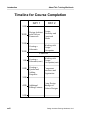
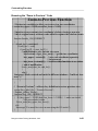
Timeline for Course Completion
DAY 1
DAY 2
9:00
10:00
Design Architect Design
Hierarchy and
in the Falcon
Functional
Framework
Blocks
11:00
Working with
Design
Viewpoints
Creating a
Schematic
12:00
LUNCH
1:00
Creating a
Schematic(cont)
Working with
Design
Viewpoints(cont)
2:00
Creating a
Symbol and
Adding
Properties
Component
Interfaces and
Registration
Additional
Editing Features
Using Design
Manager to
Release Designs
3:00
4:00
5:00
xviii
Design Architect Training Workbook, V8.5
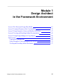
Module 1
Design Architect
in the Framework Environment
Lesson 1 The Electronic Design Data Model
1-3
Lesson 2 Common Elements of the User Interface
1-15
Lesson 3 Using Notepad to Create and Modify ASCII Files
1-37
Lesson 4 Viewing and Searching Online Documentation
1-41
Lesson 5 Using Design Manager to Copy Objects
1-49
Lab Exercises
Copying the Training Data
Using Notepad to Create and Modify ASCII Files
Viewing and Searching Online Documents
1-63
1-64
1-71
1-77
Design Architect Training Workbook, V8.5
1-1
Design Architect in the Framework Environment
Module 1 Overview
Design Architect
in the
Framework Environment
Module 1
• The Electronic Design
Data Model (EDDM)
Creating a Schematic
Creating a Symbol
and Adding Properties
Additional
Editing Features
Design Hierarchy and
Functional Blocks
Working with
Design Viewpoints
Component Interfaces
and Registration
Using Design Manager
to Release Designs
1-2
Module 2
• Common Elements of
the User Interface
• Using Notepad to
Module 3
Module 4
Create and Modify
ASCII Files
• Viewing and Searching
Online Documentation
• Using Design Manager
to Copy Objects
Module 5
Module 6
Module 7
Module 8
Design Architect Training Workbook, V8.5
Design Architect in the Framework Environment
Lesson 1
The Electronic Design Data Model
Design Architect Training Workbook, V8.5
1-3
Design Architect in the Framework Environment
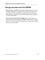
Design Architect and the EDDM
Design Architect
Symbol
Editor
Schematic
Editor
VHDL
Editor
Electronic Design
Data Model
1-4
Libraries
Design Architect Training Workbook, V8.5
Design Architect in the Framework Environment
Design Architect and the EDDM
Design Architect - a Tool Box You can think of Design Architect as a tool box
containing a collection of tools (graphic and text editors) that are used to create
and modify the data that is modeling your design. The three primary tools in
Design Architect are the Symbol Editor, the Schematic Editor, and the VHDL
Editor. Many other optional tools can be added to Design Architect through the
use of Personality Modules.
The Electronic Design Data Model (EDDM) When you use the editors in
Design Architect to enter a design, a set of design files and directories is created
called the Electronic Design Data Model (EDDM). Typically, the basic building
blocks of your design will be pre-built components that reside in libraries located
somewhere in your file system.
Design Architect Training Workbook, V8.5
1-5
Design Architect in the Framework Environment
Component Structure
(Conceptual View)
Q
R
Q
Component
Interface
Model
Table
S
Q
Pin
List
Body
Property
List
R
Q
S
Graphical Model
(Symbol)
Symbol
Symbol
Body
Pin
H
L
R_
S-
C
AT
portout
portin
Functional Model
(Schematic)
1-6
Design Architect Training Workbook, V8.5
Design Architect in the Framework Environment
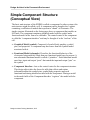
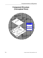
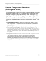
Simple Component Structure
(Conceptual View)
The basic unit structure of the EDDM is called a component. In other systems, this
unit structure might be called a cell. A component can be thought of as a sphere
containing a collection of models that represent a “chunk” of electronics. The
simple structure illustrated on the facing page shows a component that models an
S-R latch. The component contains a graphical model called a symbol and a
functional model in the form of a schematic. The control center of the component
is called the “component interface” and may be thought of as the “nucleus” of the
cell.
• Graphical Model (symbol). Composed of symbol body graphics, symbol
pins, and properties. A component may have more than one symbol model
associated with it.
• Functional Model (schematic). Describes the functional behavior of the
electronics being modeled. More than one functional model may be present. A
non-schematic functional model is called a “primitive”. Each functional model
must have input and output “ports” that match the input and output “pins” on
the symbol.
• Component Interface. Acts as the control center for the component structure.
This design object takes the form of a table that collects and retains
information about the symbol pins, symbol body properties and each
functional and timing model associated with the component. Placing a model
in the model table of the Component Interface “registers” the model with the
component.
Design Architect Training Workbook, V8.5
1-7
Design Architect in the Framework Environment
Component Structure
(Iconic View)
s-r_latch
part
s-r_latch
schematic
Contains the
Component Interface
table
schem_id
sheet1
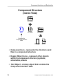
• Component Icon - represents the directories and
files in a component structure
• Design Object Icons - represent other objects
within the component structure (symbols,
schematics, sheets
• Part Object - a binary object that contains the
Component Interface table
1-8
Design Architect Training Workbook, V8.5
Design Architect in the Framework Environment
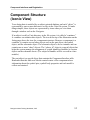
Component Structure
(Iconic View)
Your design data is modeled by an object-oriented database and each “object” is
represented by one or more directories or files in the Unix file system. To make
things simpler, these objects are represented by icons when you view them
through a window such as the Navigator.
If an object is really a Unix directory in the file system, it is called a “container.”
A container can contain other objects. The icon at the top of the illustration on the
facing page shows the icon for a component structure. Because a component is a
container, it contains several other objects such as the part object, the symbol
object, and the schematic object. The schematic object is also a container and can
contain one or more “sheet” objects. The “schem_id” object is a special object that
helps the system manage the assignment of system identifiers (handles) to various
objects on the schematic sheets. (The subject of handles will be covered in a later
module.)
The part object is a special object that contains the Component Interface table.
Remember that this table acts like the control center of the component where
information about the symbol pins, symbol body properties and each model is
collect and retained.
Design Architect Training Workbook, V8.5
1-9
Design Architect in the Framework Environment
Component Within a Component
T0
OU
GN
I
ES
T1
OU
_D
MY
0
IN
T2
OU
1
IN
2
IN
Component
Structure
Q
H
TC
Instance of
S-R_LATCH
R
LA
R_
S-
Q
S
Component
Structure
Q
R
Q
S
1-10
Design Architect Training Workbook, V8.5
Design Architect in the Framework Environment
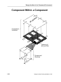
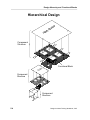
Component within a Component
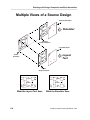
The picture on the facing page illustrates how a new design is created by placing
components within a component. Two component structures are shown: one
named S-R_LATCH and the other named MY_DESIGN. The component named SR_LATCH contains a symbol model and a functional model and is typical of a
component that might be found in a library.
A new component structure is created when you open a new schematic sheet with
Design Architect. The new component in the picture is called MY_DESIGN. In
this case, the image of the S-R_LATCH component symbol is placed on the new
schematic. Each image is called an “instance” of the S-R_LATCH and can be
thought of as an active reflection of the S-R_LATCH symbol located in the library.
Each instance of the S-R_LATCH is considered different than the symbol body,
because some of the characteristics of each instance can be changed once the
instance is placed on the new sheet. Additionally, each instance can also be
viewed as “linked” to the symbol body, which allows each instance to be
collectively or individually updated after changes are made to the symbol body in
the library.
Once you create a new schematic design, you can create a symbol to represent it.
In this case, the symbol MY_DESIGN is created with the Design Architect symbol
editor and registered with the MY_DESIGN component structure. Notice that the
new symbol contains three input pins and three output pins to match the three
input ports and three output ports on the schematic.
The new MY_DESIGN symbol can now be instantiated on a new higher-level
schematic sheet that may represent the electronics of a more complex system.
Design Architect Training Workbook, V8.5
1-11
Design Architect in the Framework Environment
Design Viewpoint
(Conceptual View)
Design
Architect
SET
VIEWPOINT
Design
Viewpoint
Editor
OPEN
SHEET
OPEN VPT
5
Source
Schematic
Simulator
Back Annotation Object
5)
+
(X 15
5
10
Simulator
Simulator
Design Viewpoint
15
10
What the Simulator Sees
1-12
Design Architect Training Workbook, V8.5
Design Architect in the Framework Environment
Design Viewpoint(Conceptual View)
Schematics are represented by files and directories in a software environment, so
they can take on some of the characteristics of a software program. For example, a
timing value can be represented by a numeric expression such as (X + 5) as shown
in the figure on the left. This expression must be evaluated to a constant before a
downstream tool like a simulator can operate on it. The object in the data model
that allows a downstream tool to view the source schematic as fully evaluated data
is called a design viewpoint.
You may conceptually think of a design viewpoint object as a picture frame
through which the downstream tool views the schematic. In your mind’s eye,
think of the image of the source schematic as being reflected onto the back of the
glass in the picture frame. Notice in the diagram that the simulator sees the fully
evaluated data through the viewpoint (15 in this case) even though the expression
on the source schematic (X + 5) doesn’t change. The value of X can be defined
elsewhere on the schematic or defined in the viewpoint itself.
Because the glass in the viewpoint protects the source schematic, you can’t
change the source schematic from the downstream tool. You can appear to change
the schematic, however, by selecting a property in the simulator Schematic View
Window and making a change. The change is recorded in a Back Annotation
object, which is conceptually represented as a transparent sheet laid over the top
of the glass in the viewpoint. In the figure, the timing value in front of the center
and gate is changed from 5 to 10 nanoseconds. The simulator sees 10 ns, as
shown in the lower figure, even though the source schematic is unchanged.
All downstream tools must view the source schematic through a viewpoint.
Typically, if a schematic doesn’t have a viewpoint, the downstream tool creates
one automatically when the tool is invoked on the design.
Viewpoints can be created and modified with a tool called the Design Viewpoint
Editor. Design Architect can also invoke on a design viewpoint (using the SET
VIEWPOINT icon) as well as a source schematic (using the OPEN SHEET icon).
When you invoke Design Architect on a design viewpoint, you may selectively
merge back annotation information from the Back Annotation object onto the
source schematic.
Design Architect Training Workbook, V8.5
1-13
Design Architect in the Framework Environment
1-14
Design Architect Training Workbook, V8.5
Design Architect in the Framework Environment
Lesson 2
Common Elements of the User Interface
Many applications in the Mentor Graphics environment share common elements.
This lesson introduces you to these common elements.
Design Architect Training Workbook, V8.5
1-15
Design Architect in the Framework Environment
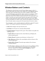
Window Buttons and Navigator Controls
Maximize
Close Window
Press and Drag
Menu Bar
Minimize
MGC
Object
Edit
Setup
Design Manager
Windows View Add
Tools
design_arch
Report
Help
Navigator
/users/train1
training
DVE
SETUP
MONITOR
TRANSCRIPT
MONITOR
NAVIGATE
TOOLS
HIER ARCHY
COMPONENT
CONFIG
TRASH
COPY
MOVE
my_dff
i
bold_browser
SETUP
SESSION
QuickPath
Accusim
QuickSimII
AIK
ic
FastScan
FlexTest
F1
F2
F3
F4
F5
Open Obje Unselect A Goto Direc Popup Men Move Obje
Copy Objec
Open Navi Select Obj Explore Pa
Change Ob
Report Inf Select All Navigator D
F6
F7
F8
S Show Refe Open Moni
C Change Re
A Check Refe
F9
F10
F11
F12
Pulldown M Command Pop Windo
Read File Close Win
i Invoking Design Architect....
Explore Down
Resize Window
1-16
Show References
Goto
Active Window
(blue border)
Design Architect Training Workbook, V8.5
Design Architect in the Framework Environment
Window Buttons and Controls
The illustration on the left show how the Design Manager appears when it is
invoked from a shell. The title bar on the window has several important controls.
When you click the Maximize button, the window expands to fill the whole
screen. Click Maximize again and the window returns to its original size. When
you click on the Minimize button, the window turns into an icon. When you
double click on the Close Window button(on the far left), the window goes away.
Finally, if you place the mouse pointer on the title bar and press the left mouse
button, you can reposition the whole window to any place on the screen. When
you move the pointer to a window corner, a Resize cursor appears, as shown in the
lower-left corner, and you can press the left mouse button to resize the window.
You can navigate, or move around in, directories and files by using the Navigator
window. The Navigator contains the following areas and controls:
• Iconic Area. Displays icons represented by icons.
• Scroll bars. Scroll iconic area vertically and horizontally.
• Navigation buttons. Navigate the file system. These buttons correspond to the
following actions:
• Explore Down. Navigates into the selected directory and displays the
objects in that directory.
• Explore Parent. Navigates up one directory or reference level.
• Show References. Replaces the current display with the references of the
selected design object.
• Explore Back to Parent. Closes the report window of the references
currently displayed.
• Go To. Displays a dialog box into which you can enter a pathname and then
moves directly to that destination. You may also type a Unix change
directory command like “cd /user/train1/training/da_n” and the
Navigator will move to that location.
Design Architect Training Workbook, V8.5
1-17
Design Architect in the Framework Environment
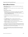
Menus and Mouse Buttons
Design Architect
MGC
File
Setup
Help
Notepad
Pulldown Menu
Cleanup Windows
Userware
Transcript
Popup Menu
Session
Setup
Open Sheet...
Design Management
Open Symbol...
Location Map
Set Working Directory:
Export Screen...
Show Location Map
Open VHDL...
Change Entry:
Set Viewpoint...
Read Map:
Open Source Code
Find Component...
MGC
QuickHDL
Select
Stroke/Drag
Menu
1-18
Design Architect Training Workbook, V8.5
Design Architect in the Framework Environment
Menus/Mouse Buttons
Pulldown Menus Place the mouse pointer on the Menu Bar item and press the
Left or Right mouse button.
Popup Menus Place the mouse pointer in the window area and press the Right
mouse button.
Graphic Elements in Menus:
• Menu items. Represent a specific task or a category of tasks. The examples
shown on the facing page are Notepad, Cleanup Windows, Userware,
Transcript, Setup, Design Management, Location Map, and Print Screen menu
items from the MGC pulldown menu.
• Cascade arrow. Indicates that a cascading menu is present.
• Separator. Divides a related group of menu items from the rest of the menu
items.
• Cascading menu. Displays to the right of the parent menu item.
• Prompt bar indicator. A colon indicating that the menu item displays a
prompt bar for additional command or function information.
• Dialog box indicator. An ellipsis indicating that the menu item displays a
dialog box for additional information to the system.
A cascading menu represents a group of tasks related to the parent menu item. On
the facing page, the cascading Location Map menu item has four tasks:(1) Set the
Working Directory, (2) Show the current location map, (3) Change an entry in the
location map, and (4) Re-read the location map from disk.
To choose the menu item that you want, you slide the mouse pointer over the
menu cascade arrow and on top of the desired menu item before releasing the
mouse button.
Design Architect Training Workbook, V8.5
1-19
Design Architect in the Framework Environment
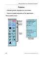
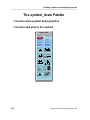
Palettes
• Default palette: displayed on invocation
• Name of palette depends on the application
Three palette areas:
schematic_add_route
SESSION
ADD/ROUTE
TEXT
DRAW
DELETE
UNDO
MOVE
COPY
UNSELECT
ALL
SET SELECT
FILTER
Select a
Palette
Common
Buttons
Schematic Palette
Display Schematic Palette
Display Default Palette
Set Default Palette
Add Instance
Back
LIBRARY
Root
CHOOSE
SYMBOL
Show Scroll Bars
ADD
WIRE
ROUTE
SELECTED
ADD BUS
/BUNDLE
FLIP
Hide Active Symbol Window
Palette
Icons
Hide Context Window
Hide Palette
Resize Palette
ROTATE
PIVOT
CONNECT
ALL
ALIGN
Palette Area
Popup Menu
SETUP
RIPPER
1-20
Design Architect Training Workbook, V8.5
Design Architect in the Framework Environment
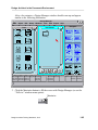
Palettes
A palette is a convenient way to execute commands without having to traverse
menu paths. You click the Select mouse button to execute a palette item. These
items fall into three categories, depending on the area of the palette.
• Palette Selection. A palette is really a group of palettes all in one area. The top
part of each application palette is identical and contains several choices, each
representing a different palette. The button for the palette that is currently
being view is highlighted in red, so if you click on it, nothing happens. When
you click on any other button, you can access the corresponding palette. The
new palette replaces the existing one.
• Common Palette Buttons. The middle area of each palette contains a
common area of buttons that perform the same function on each palette.
Many of these functions can also be found in the session popup menu.
• Palette Icons. These buttons form a subset of the total icons available and are
grouped on a palette according to function. For example, the palette on the left
contains icons that allow you to add instances to a schematic sheet and route
nets between the instance pins.
Palette selections work much the same as menu choices; that is, you may be
prompted for additional information in a dialog box or a prompt bar. In addition,
palette buttons may be grayed to indicate that the choice cannot be made. Some
buttons may require design objects to be selected before they become available,
while other buttons require that a type of window be present.
Design Architect Training Workbook, V8.5
1-21
Design Architect in the Framework Environment
Softkeys
• Indicate the operation of each function key
• They change from window to window
• They do not function as buttons (only visual)
F3
F4
F1
F2
F0
Popup Menu
Pulldown Menu
Unselect All
Add Wire
Select Area Any
Unselect Area
s
Add Bus/Bundle
Select Vertex
c
Reselect
Move
Copy
Reopen Sheet
a
F5
F6
F7
F9
F8
View Area
Place Symbol
Sel Txt & Move
Reselect
Set Grid Snap
View
All
Add
Property
Chg
Text
Value
Connect
All
s
c
Open Down
Check Sheet
Open Up
a
1-22
Design Architect Training Workbook, V8.5
Design Architect in the Framework Environment
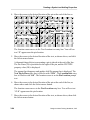
Softkeys
Softkeys are not buttons like the ones you see in a palette. Instead, the softkey area
is presented to give you a visual representation of the function keys. To execute a
softkey action, you “look up” the action you want to perform in the softkey area,
and then press the appropriate function key combination.
There are four key combinations for each function key.
• Function key alone. Several common user interface operations, such as
“Pulldown menu” and “Popup menu,” are reserved for this mode. Press the
function key by itself.
• Shifted function key. The second row of operations, which are in line with “s”
in the key, are executed by first pressing and holding the shift key while
pressing the function key. The View All function (F8) is accessed this way.
• Control + function key. The third row of operations, which are in line with
“c” in the key, are executed by pressing and holding the Control (Ctrl) key
while pressing the function key. For example, this is how you access the Move
command (F2).
• Alt + function key. The last row of operations, which are in line with “a” in
the key, are executed holding the Alt key while pressing the function key.
To remove the softkey area, use the Hide Softkeys menu item in the Softkey
menu, or the Setup > Hide Softkeys menu from the pulldown menu bar. To show
the softkey area, you access the Setup > Show Softkeys menu item from the
pulldown menu bar.
Design Architect Training Workbook, V8.5
1-23
Design Architect in the Framework Environment
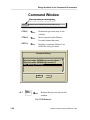
Command Window
Pops up when you start typing
session $system(“mkdir $HOME/mgc/userware/des_arch”)
CTRL P
Returns the previous entry to the
window.
CTRL N
Moves forward in the History
List and returns that entry.
CRTL H
Displays a complete History List.
Select the entry you want.
Command History
$system(“mkdir $HOME/mgc/userware/base”)
$system(“mkdir $HOME/mgc/userware”)
$set_working_directory()
OK
ALT
Back
Space
Cancel
Returns the previous entry to the
window.
Pre-V8.4 Behavior
1-24
Design Architect Training Workbook, V8.5
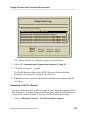
Design Architect in the Framework Environment
Command Window
When you start typing in a window, the command window automatically pops up
with your entry. You may enter commands or functions in this fashion. The name
of the active window is shown on the left side of the Command window and the
command or function you type must be defined within a scope that is visible to
this window.
A history list is keep for this window. With the Command window displayed, type
Ctrl P (for previous) to bring the last entry back into the window, type Ctrl N to
move forward in the history list, and type Ctrl H to bring up a form with all the
entries listed. Select one and click OK.
For software versions prior to V8.4, type Alt BackSpace to bring back the
previous entry.
Design Architect Training Workbook, V8.5
1-25
Design Architect in the Framework Environment
Prompt Bars
Text Entry Box
ADD PI Next Pin to Place : D
Location Info : left
Location Cursor
Pin Location
Text Location
OK
Cancel
OK
Cancel
Command Name
Stepper Button
Mid-Command Freedom
$edit_source
function_name
OK
ADD
WI Locations
repeat true
OK Cancel
Cancel
COPPIOBNext
Destination
Cancel
ADD
Pin to Place : D
Location
LocationOptions...
Info : left OK Pin
Text Location
Lets you execute an additional function
before you complete the previous one
1-26
Design Architect Training Workbook, V8.5
Design Architect in the Framework Environment
Prompt Bars
A prompt bar is a graphic aid that is displayed when you need to supply additional
information to a command. When the prompt bar is displayed, you supply the
additional information by typing in text or clicking a stepper button. Sometimes
you must supply a coordinate location by clicking on a point in a window. When
you have supplied all the necessary information, the prompt bar goes away.
Sometimes, you execute a function like ADD WIRE in the Design Architect
Schematic Editor and the prompt bar means that you are in the ADD WIRE mode.
You can keep adding wires to the schematic until you exit the mode by clicking
the Cancel button on the prompt bar.
Mid-command freedom is a feature that allows you to execute another command
before you finish executing the current command. In the bottom illustration on the
facing page, the stacked prompt bars indicate that three commands were
suspended in mid-command while a fourth command $edit_source is being
executed. Once the current command is finished executing, the system returns to
the previous command. At any time, you can click the Cancel button on the
prompt bar to clear it from the screen, but it must be the prompt bar on the top of
the stack.
Design Architect Training Workbook, V8.5
1-27
Design Architect in the Framework Environment
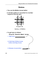
Strokes
• You use the Middle mouse button
• A strokes pattern is converted to a number
sequence from the grid
1
2
3
4
5
6
7
8
9
Unselect All
$stroke_1478963()
• To get help on strokes:
Draw the “Question Mark” stroke:
1. Start here.
2. Hold down Stroke mouse
button and drag mouse.
3. Release mouse button.
1-28
Design Architect Training Workbook, V8.5
Design Architect in the Framework Environment
Strokes
Strokes are another way of issuing commands within applications. You can
activate stroke mode by pressing the Drag/Stroke mouse button (usually the
middle button), and then you use the mouse to graphically “draw” the command.
For example, to unselect all objects in many applications, you press and hold the
Drag/Stroke mouse button and then draw a “U” on the screen. The “U” will show
graphically on the screen in the default stroke style and color, normally a narrow
red line. When you have finished drawing the “U,” release the Drag/Stroke mouse
button. The command executes immediately and all objects are unselected.
A stroke is defined by a sequence of grid coordinates, as shown in the figure on
the left. This grid is called the stroke recognition grid. When you draw a stroke,
the pattern is overlaid on the recognition grid, and a sequence of numbers is
derived. If this sequence matches an existing defined sequence, the command for
that sequence is executed. If the sequence is not defined, you get a “not defined”
message.
In the example on the left, if you draw the “U” stroke, the pattern is interpreted as
the number sequence 1478963. This is mapped to the function $stroke_1478963()
which is defined as Unselect All. If you draw a “?” stroke, a quick help chart on
the available strokes appears as shown on the following page.
Design Architect Training Workbook, V8.5
1-29
Design Architect in the Framework Environment
Quick Help on Strokes
Quick Help on Strokes
Text Window Strokes
Dialog Box Strokes
Copy
Paste from Clipboard
3214789
258
Copy to Clipboard
Undo
852
7412369
Cut (to Clipboard)
Unselect
1236987
1478963
Delete
Close Window
741236987
456
Draw Window
Close Window
75357
654
Execute
456
Cancel
654
Palette Strokes
Show Parent Palette (Back)
258
Show Top Palette (Root)
852
Other Strokes
Execute Last Menu
12369
Execute Prompt Bar
456
Cancel Prompt Bar
654
Help on Strokes
123658
Move
74159
Stroke Recognition Grid
1
2
3
4
5
6
7
8
9
Use the mouse to draw strokes while holding
down the middle mouse button and moving
the mouse in the stroke path. Strokes are
recognized by fitting the stroke path onto a
3x3 grid which determines a numerical sequence.
Close
1-30
Ref Help
Design Architect Training Workbook, V8.5
Design Architect in the Framework Environment
Quick Help on Strokes
If you draw a question mark stroke “?” in a Design Manager window, the Quick
Help on Strokes chart appears as shown on the facing page. This chart defines the
strokes that are available to you in that active window. Strokes are one of the most
productive methods for executing commands, because all you have to do is wiggle
the mouse in small patterns, instead of moving the pointer half way across the
screen to click a palette icon or reach a pulldown menu..
It is often helpful to make a photocopy of this form, cut it up into strips and tape
the strips on the edges of your display until you learn the strokes. After you use
the strokes over time, you will remember them and they will come to you
naturally, almost without thinking. Many of the strokes that you will learn from
this chart will carry over to other applications, so they are well with the effort to
learn.
Design Architect Training Workbook, V8.5
1-31
Design Architect in the Framework Environment
Transcript Window
Click Here
MGC
Object
Edit
Setup
Design Manager
Windows View Add
Tools
design_arch
Help
Navigator
Session - Transcript
DVE
i
bold_browser
Report
QuickPath
Accusim
QuickSimII
AIK
ic
FastScan
FlexTest
$set_active_window(“to
$minimize_window();
$set_active_window(“se
$unselect_all;
$set_active_window(“to
$update_window();
$select_tool("desig
$setup_invoke_tool(“MG
extern qual_script#
$message(“Invoking
$writeln(“/net/tria
// “/net/triassic/scra
$invoke_tool(“/net/
$set_active_window(“se
$create_notepad(“”,
$set_active_window(
$$close_window(@dis
// Error: $stroke_258
// Error: Binding no
$unselect_all();
$set_active_window(“se
$select_tool("ic”,“
$setup_invoke_tool(“MG
F1
F2
F3
F4
F5
Open Obje Unselect A Goto Direc Popup Men Move Obje
Copy Objec
Open Navi Select Obj Explore Pa
Change Ob
Report Inf Select All Navigator D
F6
F7
F8
S Show Refe Open Moni
C Change Re
A Check Refe
F9
SETUP
SESSION
SETUP
MONITOR
TRANSCRIPT
MONITOR
NAVIGATE
TOOLS
HIER ARCHY
COMPONENT
CONFIG
TRASH
COPY
MOVE
F10
F11
F12
Pulldown M Command Pop Windo
Read File Close Win
i
Transcript Window
1-32
Design Architect Training Workbook, V8.5
Design Architect in the Framework Environment
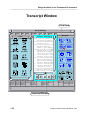
Transcript Window
A transcript is a record of the events that occur during a session. Although you can
trigger events in a variety of ways such as clicking an icon or choosing a menu
item, the actions taken are taken by executing a series of AMPLE functions. The
transcript is a record of the AMPLE functions. Other information, such as a
warning or error messages, are also recorded in the transcript.
It is possible to select text from a Transcript, then copy and paste the text to an
ASCII file using the Notepad Editor. The ASCII text can then be saved as a macro
file for later execution. This is a handy feature for creating application startup files
and custom userware files.
Design Architect Training Workbook, V8.5
1-33
Design Architect in the Framework Environment
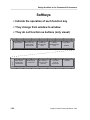
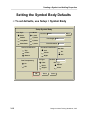
Session Setup
SETUP
SETUP
SESSION
Session Setup
Select Input Device:
Show Status Line
X11_POINTER
Show Softkey Area
Show Symbol Window
Show Menu Bar
Show Context Window
Show Session Title
Show Palette
Show Message Area
Double Click Speed
Window Layout
Slow
Stacking
Up Down Tiling
Dialog Box
Move Dialog Box
Quadrant Tiling
Resize Dialog Box
Left Right Tiling
Fast
Ask User for Position
OK
1-34
Reset
Cancel
Design Architect Training Workbook, V8.5
Design Architect in the Framework Environment
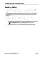
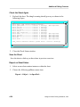
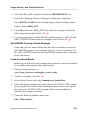
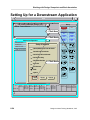
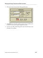
Session Setup
When you click on a Session Setup icon or execute the pulldown menu MGC >
Setup > Session, the form to the left appears. You can hide any number of out
lying window areas, such as the palette and softkey area in order to gain more
work space in the session area. In addition, you can set the speed of the mouse
click and specify how you want the working windows in the session area to be
displayed.
If a dialog box appears in an area that blocks your view of information, you can
easily move the dialog box by taking the following steps:
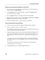
1. From any where in the Session area, press the right mouse button and click
on Move Dialog Box as shown in the illustration on the left page:
2. Move the “shadow box” to a new location, then click the select mouse
button.
Design Architect Training Workbook, V8.5
1-35
Design Architect in the Framework Environment
1-36
Design Architect Training Workbook, V8.5
Design Architect in the Framework Environment
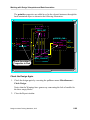
Lesson 3
Using Notepad to Create and Modify
ASCII Files
The Mentor Graphics environment provides a simple text editor that you can use
to create and modify ASCII text files. In this course, you will use this editor to
create and modify files that will customize the user interface.
Design Architect Training Workbook, V8.5
1-37
Design Architect in the Framework Environment
Editing Files with Notepad
MGC
File
Edit
Search
View
Design Manager
Options Help
Navigator
Notepad - (untitled)
// “Zoom to Previous” - add new key definition to
Undo = “Zoom to Previous”;
extern $key_label_f4s
//$update_softkey_labels();
Redo
function $key_f4s(), INDIRECT
{ if ((last_upper !=
VOID) && (last_lower != VOID)
Move
//view area stroke is done
Copy to Cursor
$view_area([last_upper,
last_lower]);
else
Cut first view an area using the
$message(“You must
}
Copy to Clipboard
System
Paste
Session
X
Delete
Select
SETUP
SESSION
SETUP
MONITOR
TRANSCRIPT
MONITOR
NAVIGATE
TOOLS
HIER ARCHY
COMPONENT
CONFIG
TRASH
Unselete
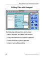
The following editing actions can be done:
COPY
MOVE
• Move, duplicate, and delete selected text
F1
F2
F3
F4
F5
Open Obje Unselect A Goto Direc Popup Men Move Obje
Open Navi Select Obj Explore Pa
Copy Objec
Report Inf Select All Navigator D
Change Ob
F6
F7
F8
S Show Refe Open Moni
C Change Re
A Check Refe
F9
F10
F11
F12
Pulldown M Command Pop Windo
Read File Close Win
• Copy selected text into a system clipboard
i Invoking Design Architect
• Insert text from a system clipboard
• Undo or redo editing actions
1-38
Design Architect Training Workbook, V8.5
Design Architect in the Framework Environment
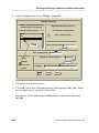
Editing Files with Notepad
The Notepad editor enables you to accomplish several types of actions on text
contained within a Notepad window. You can do any of the following from the
Notepad popup menu, which is illustrated in the figure on the facing page.
• Undo or redo editing actions. If you want to reverse the effects of an action,
you can use the Undo popup menu item to return the file to the way it was
before the last action. If you decide you want that last action after all, you can
use the Redo popup menu item.
• Move, duplicate, and remove selected text. You can use the Move or Copy
to Cursor popup menu items to move text to a different location or to copy it
to the cursor location. You can delete selected text into either a System paste
buffer or into a Notepad Session paste buffer using the Cut popup menu items;
the System buffer is the default.
• Copy selected text into a clipboard. If you have text that you want to transfer
to another location, you can copy it into either the Session clipboard, the
System clipboard, or the X window cut buffer using the Copy to Clipboard
popup menu item. A clipboard essentially acts as a paste buffer within the
Notepad session or between applications you have active on your workstation;
the System clipboard is the default.
• Insert text from a clipboard. If you have text copied to a Session clipboard or
a System clipboard, you can copy the text into the file you are editing using the
Paste popup menu item; the System clipboard is the default.
• Select and unselect text. You can use the Select popup menu item to select
text on which you want to do other editing actions. You can also select text by
pressing the Select mouse key, dragging the cursor to the end of the required
text, and releasing the Select mouse button. If text is highlighted, you can
remove the highlighting using the Unselect popup menu item.
Design Architect Training Workbook, V8.5
1-39
Design Architect in the Framework Environment
1-40
Design Architect Training Workbook, V8.5
Design Architect in the Framework Environment
Lesson 4
Viewing and Searching Online
Documentation
A large resource of online documentation can be accessed through the BOLD
Browser. This lesson shows you how to view the vast array of online
documentation and perform a full text search on any given topic.
Design Architect Training Workbook, V8.5
1-41
Design Architect in the Framework Environment
Online Help
• Help menu options:
MGC
File
Design Architect
Setup
Help
On Commands
On Functions
On Keys
On Strokes...
On Menus
On Palettes
Open Tutorial
Open Procedure
Open Index
Open Bookcase
More Help
On Properties
On Shortcuts
On Help
On Version
On SupportCenter
Release Notes Highlights
Documentation Roadmap
1-42
Design Architect Training Workbook, V8.5
Design Architect in the Framework Environment
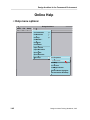
Online Help
You can access Design Architect online help through the Help menu in the menu
bar. The following list describe what you can access from online help:
• On Commands. Provides Quick Help or Reference Help of Design Architect
commands or a summary table of commands and functions. For a list of
commands in the active window type * then Ctrl-SHIFT ?
• On Functions. Provides Quick Help or Reference Help of Design Architect
functions or a summary table of commands and functions.
• On Keys. Provides help on predefined keys or a table of logical function key
name mappings.
• On Menus. Provides help on the types of menus and the contents of each
Design Architect menu.
• On Palettes. Provides a description of the Design Architect palette menus.
• On Strokes. Provides a dialog box on strokes for the active window.
• Open Tutorial. Brings up a BOLD Browser window that displays the Getting
Started with Design Architect Training Workbook.
• Open Procedure. Brings up a BOLD Browser window that displays the
Operating Procedures section of the Design Architect User's Manual.
• Open Index. Brings up a BOLD Browser window that contains the index of
the Design Architect User's Manual.
• Open Bookcase. Brings up a BOLD Browser window that contains the list of
documents that compose the Design Creation documentation set.
• More Help. Information on properties, short cuts, customer support, release
notes, documentation roadmap, on help, and current version.
Design Architect Training Workbook, V8.5
1-43
Design Architect in the Framework Environment
Opening Online Documents
MGC
File
Search
Setup
BOLD Browser
Help
Open Document from Bookcase
System-defined Bookcases
Double Click
on Bookcase
Falcon Framework
AMPLE Reference Manual
AMPLE User’s Manual
Board Flow Sequencer Manual
Double Click
BOLD Administrator User’s Reference Manual
on Manual
BOLD Browser Reference Manual
BOLD Browser User’s Manual
Common Environment Variables Quick Reference, Release A.1 - F
Common User Interface Manual
Common User Interface Reference Manual
Customizing the Common User Interface
Descision Support System (DSS) Reference Manual
OK
Reset
Cancel
Help
• Double click on a bookcase to list the manuals
within
• Select the manual and execute the form to open
the document
1-44
Design Architect Training Workbook, V8.5
Design Architect in the Framework Environment
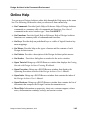
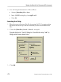
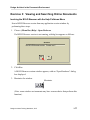
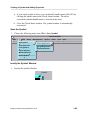
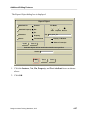
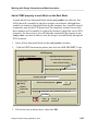
Opening Online Documents
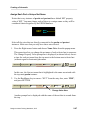
Online documents are grouped into bookcases. When you choose File > Open >
Bookcase..., the form illustrated on the left appears. When you want to open a
bookcase to view the documents, just double click on the bookcase name. To open
a document, double click on the document name.
All online training documents are contained in a bookcase named Training.
Design Architect Training Workbook, V8.5
1-45
Design Architect in the Framework Environment
Searching and Traveling in Documents
MGC
File
Edit
BOLD Browser
Setup
Report
Search
Help
Customizing the Common User Interface
Index
Search
Table of
Contents
Previous
Page
4
8
Next
Page
2
6
Document Area
Next Page
Previous Page
Goto
Travel Log
Clone
Zoom
Next
Page
Previous
Page
Scroll
Page Up
9
Pg Up
Page Number...
Scroll
Page Down
Table of Contents
3
Pg Dn
Index
Section
Next
Index
Previous
Section
By Name...
Text Search
Search for
softkey
Allow compound or proximity ?
Match upper/lower case
1-46
No
Yes
Order search result document list by
Any case
Priority
Exactly
Alphabetically
Design Architect Training Workbook, V8.5
Design Architect in the Framework Environment
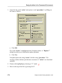
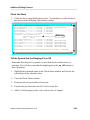
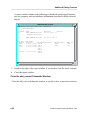
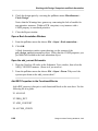
Searching and Traveling in Documents
You can travel around in INFORM documents to continue with your current
subject matter or to find additional information by one of the following methods:
• Icons in the title area. Clicking on these icons enables you to travel to the
table of contents, index, a previous page, or the next page.
• Popup menu or function keys. Enables you to travel to the table of contents,
index, a previous page, the next page, a particular page number or section, or to
pages and documents that you previously viewed.
• Hypertext links. Enables you to travel to hyperlinked pages in the same
document or in different documents. Hyperlinks are color highlighted on color
displays and outlined on black-and-white displays. You click on the
highlighted reference to move to that location.
The BOLD Browser incorporates a full text search index, which is a list of words
and their locations in the online library. When you initiate a search for a word or
word phrase, the BOLD Browser searches this index, rather than scanning through
the text of all the documents at search time. This type of search is significantly
faster than textual scans.
You can specify that BOLD search for specific needs, such as the following:
• Whether the word is part of a compound word.
• Determine letter case.
• Find variant forms of hyphenated words and plural forms.
• Restrict the search through certain document or a bookcase.
When the BOLD Browser locates the occurrences of the word(s) you requested, it
displays a “Search Results” window where you can see a list of documents
containing the term. You can click on the document titles to disclose lists of pages
where the term occurs.
Design Architect Training Workbook, V8.5
1-47
Design Architect in the Framework Environment
1-48
Design Architect Training Workbook, V8.5
Design Architect in the Framework Environment
Lesson 5
Using Design Manager to Copy Objects
Changing the location of your design data in the file system should always be
done with Design Manager. This lesson explains why you need to use Design
Manager and how to successfully copy objects.
Design Architect Training Workbook, V8.5
1-49
Design Architect in the Framework Environment
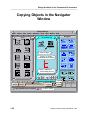
Copying Objects in the Navigator
Window
MGC
Object
Edit
Setup
Design Manager
Windows View Add
Tools
design_arch
Report
Help
Navigator
.../shared/training
DVE
qsim851nwp
QuickPath
QuickSimII
AIK
ic
FastScan
FlexTest
TRANSCRIPT
MONITOR
NAVIGATE
TOOLS
HIER ARCHY
COMPONENT
CONFIG
TRASH
COPY
MOVE
1. Click on Object
2. Draw "C" Stroke
(with middle mouse button)
Accusim
SETUP
MONITOR
da85nwp
i
bold_browser
SETUP
SESSION
3. Enter pathname of
local training directory
4. Click OK
F1
F2
F3
F4
F5
F6
Open Obje Unselect A Goto Direc Popup Men Move Obje
Copy Objec
Open
Obj Explore/users/train1/training/da_n
Pa
COPNavi
OB Select
Destination
Change Ob
Report Inf Select All Navigator D
i Copy operation was successful
1-50
F7
F8
S Show Refe Open Moni
Re
C Change
Options...
OK
A Check Refe
F9
F10
F11
F12
Pulldown M Command Pop Windo
Read File Close Win
Cancel
5. Look for message
Design Architect Training Workbook, V8.5
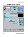
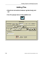
Design Architect in the Framework Environment
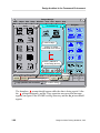
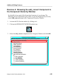
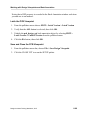
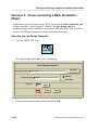
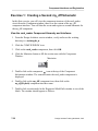
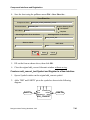
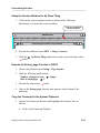
Copy Objects in the Navigator Window
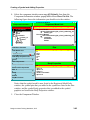
The illustration to the left shows the steps required to copy an object to another
location in the directory structure. An alternative to using the “C” stroke is to
press the right mouse button and execute Edit > Copy: from the popup menu.
Design Architect Training Workbook, V8.5
1-51
Design Architect in the Framework Environment
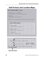
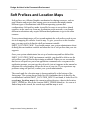
Soft Prefixes and Location Maps
MGC_LOCATION_MAP_2 force
$CUSTOM_LIB -t LIBRARY
/usr2/dburnette/my_custom_parts
$PROJECT
/usr2/dburnette/project
INCLUDE /usr1/team_project/mgc_location_map
MGC_LOCATION_MAP_1
$MGC_GENLIB
/usr1/mgc_libs/gen_lib
#$MGC_LSLIB
#/usr1/mgc_libs/ls_lib
$PROJECT
/usr1/team_project
(environmental
variable)
$MGC_HOME/etc/shared/mgc_location_map
$MGC_HOME/etc/mgc_location_map
./mgc_location_map
Search Path
MGC_LOCATION_MAP=/users/dburnette/my_map
Search Starts Here
1-52
Design Architect Training Workbook, V8.5
Design Architect in the Framework Environment
Soft Prefixes and Location Maps
Soft prefixes are a Mentor Graphics mechanism for sharing resources, such as
parts libraries and project data, among users on networks that might contain
different types of workstations with different operating systems and
configurations. Soft prefixes make it possible for users to access these shared
resources in the same way from any workstation on the network, even though
different workstations may require different hard pathnames to get to the same
resource.
Your system administrator will set up and maintain the soft prefixes used at your
site in a mapping file called a location map. To give you access to this location
map, you may need to define the shell environment variable
$MGC_LOCATION_MAP. You should contact your system administrator about
defining this environment variable and about the set of soft prefixes that your site
supports.
Once your system administrator has set up a location map and has defined the
$MGC_LOCATION_MAP environment variable, you should be able to use the
soft prefixes you will find in this training workbook. When you see an example
that uses a soft prefix as part of an application command or as a response to an
application prompt, you can type the soft prefix just as it appears in the manual or
substitute the corresponding soft prefix in use at your site. If you experience any
problems using soft prefixes, contact your system administrator.
The search path for a location map is shown graphically at the bottom of the
facing page. The system always looks first for a pathname that is defined by the
environmental variable $MGC_LOCATION_MAP. If not found, it looks for a file
named mgc_location_map in the current working directory, then in the location
$MGC_HOME/etc, then in the location $MGC_HOME/shared/etc. As soon as it
finds a map in this search, the search stops and that map is used.
Design Architect Training Workbook, V8.5
1-53
Design Architect in the Framework Environment
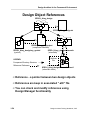
Design Object References
$PROJ_A/my_design
$PROJ_A/my_design.txt
$PROJ_A/my_design/part
(component interface)
$PROJ_A/my_design/my_symbol
(symbol)
LEGEND:
Component Directory Structure
Reference Pathname
$PROJ_A/my_design/schematic
(schematic)
Attribute
File
sheet1.mgc_sheet.attr
$PROJ_A/my_design/schematic/sheet1
(schematic sheet)
• Reference - a pointer between two design objects
• References are keep in associated “.attr” file
• You can check and modify references using
Design Manager functionality
1-54
Design Architect Training Workbook, V8.5
Design Architect in the Framework Environment
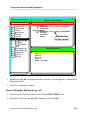
Design Object References
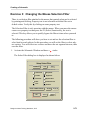
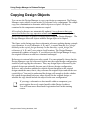
A reference is a pointer from one design object to another design object. Each
reference consists of the pathname to the design object, its type, and a version
specifier. References show relationships between design objects.
Design Architect creates references within the component. You can create and
modify references using the Design Manager. You can modify DA-created
references using the Design Manager or Design Architect. However, if you
modify these references within the Design Manager, you run the risk of modifying
them incorrectly.
You can display design object references by invoking the Report > Show
References menu path in the Design Manager pulldown menu or you can click on
the Show References (right arrow) icon in the Navigator window. The Design
Manager also provides other navigation buttons to allow you to explore a design
object's references, enabling you to traverse the design hierarchy.
The illustration on the facing page shows two concepts: (1) the component
hierarchy and the reference pathnames, and (2) references that are created by the
Design Manager, and those that are created by Design Architect. The component
hierarchy is defined by the solid arrows; the reference pathnames are defined by
the dashed arrows.
When a symbol or schematic sheet is created, they are placed under the specified
component. Reference pathnames are automatically defined by Design Architect.
Thus, the symbol model $PROJ_A/my_design/my_design contains a reference to
the component interface $PROJ_A/my_design/part. Notice that
$PROJ_A/my_design/part also contains a reference to the symbol
$PROJ_A/my_design/my_design.
The schematic model also contains a reference to $PROJ_A/my_design/part. In
addition, the schematic model contains a reference to the sheet
$PROJ_A/my_design/schematic/sheet1 and sheet1 contains a reference back it its
parent schematic. The references for sheet1 are keep in an associated file called a
“.attr” file.
Design Architect Training Workbook, V8.5
1-55
Design Architect in the Framework Environment
Copying Design Objects
• In Design Manager
o Copy by containment or by reference
• Resolved references are updated
• Unresolved references remain unchanged
external
External
Reference
first_design/B
first_design/C
first_design
original
A
original
Original
Reference
B
original
Original
Reference
C
copied_design/B
copied_design/C
copied_design
copy
A
1-56
copy
Updated
Reference
B
Updated
Reference
C
Design Architect Training Workbook, V8.5
Design Architect in the Framework Environment
Copying Design Objects
You can use the Design Manager to copy your design or component. The Design
Manager copies objects in two modes: by reference or by containment. The simple
copy uses containment to determine which objects are copied. All objects
contained in the component container are copied.
All resolved references are automatically updated. Any references that were
unresolved before the copy operation remain unchanged. You can modify these
unresolved references to point to existing objects using the Design Manager. The
Design Manager allows all objects within a design object to be copied.
The figure on the facing page shows schematic reference updating during a simple
copy operation. A set of schematics A, B, and C is copied from the first_design
directory to the copied_design directory. In the directory, copied_design, the
references of A, B, and C now point to local locations. The Design Manager
automatically updates references. If you did not use the Design Manager to copy,
the original references would have remained unchanged.
References to external objects are also copied. You can optionally choose that the
Design Manager copy the referenced objects into the copied design configuration,
instead of just copying the references. Thus, any design object referenced by the
original design can optionally become part of the new design configuration.
However, any references attached to outside objects that point to the original
design remain the same; that is, they reference the original object and not the new
copied object. You need to understand the design well enough to decide whether
the copied design should reference other objects like the original design, or
whether the copy should include the objects in the new configuration.
Note
If you copy a schematic or sheet model within a component, you
must register the newly-copied model within Design Architect.
You will learn more about model registration later in this training
course.
Design Architect Training Workbook, V8.5
1-57
Design Architect in the Framework Environment
Moving and Deleting Design Objects
• Resolved references are updated
• Unresolved references remain unchanged
• References to moved/deleted object outside or at
the same level as the component are not updated
external
External
Reference
first_design
original
original
first_design/B
A
Original
Reference
original
first_design/C
B
Original
Reference
C
moved_design/B
moved_design/C
moved_design
copy
A
1-58
copy
Updated
Reference
B
Updated
Reference
C
Design Architect Training Workbook, V8.5
Design Architect in the Framework Environment
Moving and Deleting Design Objects
You can use either the Design Manager to move or delete a design or component.
You can also use Integrated Design Management (iDM) functions, which enable
you to manage design data that you create in Mentor Graphics applications by
providing easy access to copy, move, delete, and change references.
In essence, a moved design object is one that is copied and then deleted. When
you move an object within a component or design, all objects in the containment
hierarchy of the selected object are also moved. When you move design objects
that refer to other design objects in the selected set, the Design Manager
automatically updates those references to reflect the new location. Unresolved
references or references to external objects remain unchanged.
Any design objects that reference the moved object within the containment of a
component are also automatically updated to reflect the new location. However,
any external references that point to the moved object are not updated; that is, they
continue to point to a design object that no longer exists. You need to understand
the design well enough to decide whether moving the design will break external
references.
The Design Manager allows all objects within the component container to be
moved with the exception of symbols. Symbols are not allowed to be moved
outside of their owner component container. It you attempt to move a symbol
outside of its component container, Design Manager issues an error message and
does not move the symbol.
When you delete an object, all objects and references in the containment hierarchy
are also deleted. Any external references that point to the deleted object are not
updated and are, therefore, invalid; that is, they simply point to an object that no
longer exists.
Design Architect Training Workbook, V8.5
1-59
Design Architect in the Framework Environment
Checking and Changing Design
References
CHECK
REFS
Fix Broken References
List of broken reference pathnames
$TRAINING/da_n/lib/and2/part
$TRAINING/da_n/lib/and2/and2
Change reference pathnames by entering “from” and “to” patterns
From:
To: component_lib/and2
lib/and2
To:
From:
OK
1-60
Reset
Cancel
Help
Design Architect Training Workbook, V8.5
Design Architect in the Framework Environment
Checking and Changing Design
References
It is a good practice to always check for broken references before you invoke an
application on design data that has been relocated. You can check for broken
references by selecting the icon in the Navigator window that represents the top
(root) level of the design. When you click on the CHECK REFS icon in the
Design Manager palette, a search for broken design references begins at that point
and extends down the tree.
Broken references are reported in the Fix Broken References form as shown on
the left. You may fix a broken reference by typing the complete “old” pathname in
the left entry box, then the complete “new” pathname in the right entry box. To
save time typing, you may just specify a pathname segment. For example, in the
illustration on the left, the broken reference was created by someone changing the
component_lib directory name to lib. You may fix this broken reference by
replacing the pathname segment lib/and2 with component_lib/and2. The
important thing to keep in mind is to make sure that the pathname segment is
unique, so you won’t be changing similar correct pathnames in other branches
from right to wrong.
It is a good practice to always repeat the CHECK REFS operation until the
message “No broken references were found” is reported.
Design Architect Training Workbook, V8.5
1-61
Design Architect in the Framework Environment
1-62
Design Architect Training Workbook, V8.5
Design Architect in the Framework Environment
Lab Exercises
Installing the Training Data
Before attempting to perform the lab exercises in this module, make sure that the
design data for this Design Architect training program has been installed on your
network. The training data should be at the following path:
$MGC_HOME/shared/training/da85nwp.
If you can’t find the design data, contact you system administrator for assistance
or refer to the Mentor Graphics manual titled Installing Mentor Graphics
Software for Falcon Framework Products.
Print Out the Lab Exercises
If you are reading this workbook online, you might want to print out these lab
exercises to have them handy when you are at your workstation.
Design Architect Training Workbook, V8.5
1-63
Design Architect in the Framework Environment
Exercise 1: Copying the Training Data
In this training course, you will be creating a hierarchical design from training
data supplied from a read-only master location. Since you will be modifying the
data, you must first copy the data to a place in your local directory structure.
1. Log in to your workstation.
Log in by entering your user name, password, and home directory pathname
assigned by your Instructor.
User Name: __________________________________________
Password:____________________________________________
Home Directory pathname:______________________________
2. Bring up a shell, set the directory to your home directory and enter the
following command:
$ $MGC_HOME/bin/dmgr
1-64
Design Architect Training Workbook, V8.5
Design Architect in the Framework Environment
After a few minutes, a Design Manager window should come up and appear
similar to the following illustration:
MGC
Object
Edit
Setup
Design Manager
Windows View Add
Tools
design_arch
Report
Help
Navigator
/users/train1
SETUP
MONITOR
TRANSCRIPT
MONITOR
NAVIGATE
TOOLS
HIER ARCHY
COMPONENT
CONFIG
TRASH
COPY
MOVE
training
DVE
i
bold_browser
SETUP
SESSION
QuickPath
Accusim
QuickSimII
AIK
ic
FastScan
FlexTest
F1
F2
F3
F4
F5
Open Obje Unselect A Goto Direc Popup Men Move Obje
Open Navi Select Obj Explore Pa
Copy Objec
Report Inf Select All Navigator D
Change Ob
F6
F7
F8
S Show Refe Open Moni
C Change Re
A Check Refe
F9
F10
F11
F12
Pulldown M Command Pop Windo
Read File Close Win
i
3. Click the Maximize button to fill the screen with Design Manager (or use the
“Full size" window menu option).
Maximize
Design Architect Training Workbook, V8.5
1-65
Design Architect in the Framework Environment
(Note: some window environments may have a menu choice that performs this
function.)
Within the Session window, the Tools window is on the left and the Navigator
window is on the right. The Navigator window displays the contents of the
current working directory which is typically the shell directory from which
Design Manager was invoked.
The Navigator window is the active window which is identified by the blue
border. All the pulldown menus in the top banner are associated with the
Navigator window at this time. The icons you see in the Navigator window
reflect the contents of you working directory.
The Tools window displays the tool icons representing the applications in your
hotbox directory.
4.
If the training directory doesn't already exist, create it now as follows:
a. Select the following menu item from the Design Manager menu bar:
Add > Directory:
The Add Directory prompt bar is displayed.
b. Fill in the ADD DIRECTORY prompt bar as shown below.
ADD DI
Directory Pathname
training
OK
Cancel
c. Click OK. You will see the training directory added to the list of other
objects displayed in the Navigator window.
5. View the contents of the training directory.
a. Double Click on the training directory icon to expose its contents. There
should be nothing in the training directory at this time.
6. Navigate to the $MGC_HOME/shared/training directory as follows:
1-66
Design Architect Training Workbook, V8.5
Design Architect in the Framework Environment
a. Click the Go To button in this Navigator window as illustrated below:
b. Enter the following in the text entry box: $MGC_HOME/shared/training
c. Click OK.
The Navigator window displays the $MGC_HOME/shared/training
directory in the master tree.
7. Follow the directions in the illustration on the next page to copy the da85nwp
training data to your local training directory.
Design Architect Training Workbook, V8.5
1-67
Design Architect in the Framework Environment
MGC
Object
Edit
Setup
Design Manager
Windows View Add
Tools
design_arch
Report
Help
Navigator
.../shared/training
DVE
qsim851nwp
QuickPath
QuickSimII
AIK
ic
FastScan
FlexTest
TRANSCRIPT
MONITOR
NAVIGATE
TOOLS
HIER ARCHY
COMPONENT
CONFIG
TRASH
COPY
MOVE
1. Click on Object
2. Draw "C" Stroke
(with middle mouse button)
Accusim
SETUP
MONITOR
da85nwp
i
bold_browser
SETUP
SESSION
3. Enter pathname of
local training directory
4. Click OK
F1
F2
F3
F4
F5
F6
Open Obje Unselect A Goto Direc Popup Men Move Obje
Open
Copy Objec
Obj Explore/users/train1/training/da_n
Pa
COPNavi
OB Select
Destination
Report Inf Select All Navigator D
Change Ob
i Copy operation was successful
F7
F8
S Show Refe Open Moni
Re
C Change
Options...
OK
A Check Refe
F9
F10
F11
F12
Pulldown M Command Pop Windo
Read File Close Win
Cancel
5. Look for message
The hourglass
prompt should appear while the data is being copied. After
the
prompt disappears, and the Copy operation was successful message
appears, navigate to the $HOME/training directory and the da_n icon should
appear.
1-68
Design Architect Training Workbook, V8.5
Design Architect in the Framework Environment
8.
View the contents of the da_n directory, by double clicking on the da_n icon.
The contents of this directory includes the following:
• ample_source -- contains information that you will use in customization
exercises later in this course.
• card_reader -- an empty directory that will eventually be turned into a
component container.
• com -- contains some files that you will use later in this course.
• component_lib -- contains some library components that you will use
later in this course.
Design Architect Training Workbook, V8.5
1-69
Design Architect in the Framework Environment
1-70
Design Architect Training Workbook, V8.5
Design Architect in the Framework Environment
Exercise 2: Using Notepad to Create and Modify
ASCII Files
During this training course you will have the opportunity perform several user
interface customizing exercises. You customize the user interface by creating
ASCII files containing AMPLE code. You then save these files in predefined
locations. In the following exercise, you will be introduced to the Notepad editor
which is a tool used in customizing. Because the use of strokes will increase your
productivity, you will begin learning simple strokes that perform tasks like Copy,
Move and Delete. These same strokes will be used throughout this course in
applications like the Schematic Editor and the Simulator to perform similar tasks.
Creating a New File with Notepad
1. From the Design Manager Session Window, choose:
MGC > Notepad > New
A Notepad window appears on the screen, identified by the name
Notepad - (untitled) in the title area.
2. Choose the (Menu Bar) View > Wrap menu item.
3. Click the “Word” button under “Mode” and the “Yes” button for “Wrap to
Window Width.”
This controls the amount of characters on one line in the ASCII file.
4. Click OK.
5. Select the pulldown meu item File > Import...
6. Click the Navigator button, navigate to the file ...training/da_n/com/
notepad_text.ascii, select the filename, then click OK.
7. The following text is imported into the new NotePad session:
This is a practice Notepad Editor session. Within this practice session,
you will search for and replace text, copy text, move text, delete text,
and undo the last action.
Design Architect Training Workbook, V8.5
1-71
Design Architect in the Framework Environment
8. Save the Notepad information to a file as follows:
a. Choose: (Menu Bar) File > Save
b. Enter: $HOME/training/da_n/com/myfile.ascii
c. Click OK.
Searching for a String
1. Move the cursor to the top of the file by pressing Ctrl-T. (You must position
the cursor back at the top of the file each time you wish to search the entire
file.)
2. Choose the (Menu Bar) Search > Search... menu path.
Notepad displays the “Search” dialog box. Search for the string “text” by
filling out the form as shown below:
Search
Search For
text
Search Direction
Pattern Type
Forward
Regular Expression
Backward
String
Search Area
Match Case
All
Selected Area
OK
Select on Find
Cancel
3. Click OK.
1-72
Design Architect Training Workbook, V8.5
Design Architect in the Framework Environment
4. Notepad highlights the word “text” after the word “replace.”.
This is a practice Notepad Editor session. Within this practice session,
you will search for and replace text , copy text, move text, delete text,
and undo the last action.
5. Repeat the search by choosing:
(Menu Bar) Search > Search Again > Forward
6. Notepad highlights the word “text” after to the word “copy.”.
This is a practice Notepad Editor session. Within this practice session,
you will search for and replace text, copy text , move text, delete text,
and undo the last action.
7.
Unselect the string “text” by drawing a “U” stroke
.
Searching for and Replacing a String
1. Go back to the top of the file by pressing Ctrl-T.
2. Display the “Search and Replace” dialog box by choosing:
(Menu Bar) Search > Replace...
Design Architect Training Workbook, V8.5
1-73
Design Architect in the Framework Environment
3. Search for the word “action” and replace it with “procedure”, by filling out
the form as follows:
Search and Replace
Search For
action
Replace With
procedure
Search Direction
Search Area
Forward
All
Backward
Selected Area
Replace all
Pattern Type
Regular Expression
Match case exactly
String
Ask before replacing
Select on replace
OK
Cancel
a. Click OK.
The word “action” is highlighted in the Notepad window. A “Replace?”
dialog box asks you to confirm the replace operation.
b. Click Yes.
Notepad replaces the string “action” with the string “procedure”. The
message window informs you that one occurrence of “action” was found and
replaced.
4. Remove the highlighting by drawing a “U” stroke
.
5. Move to the top of the file by pressing Ctrl-T.
1-74
Design Architect Training Workbook, V8.5
Design Architect in the Framework Environment
Practice Copying, Moving and Deleting Text
1. Activate the Notepad window, if it is not already active.
2. Choose (Menu Bar)View > Show Line Numbers
3. Select the first sentence by placing the mouse cursor on the first character, then
press the left mouse button and drag across the sentence.
.
This is a practice Notepad Editor session. Within this practice session,
you will search for and replace text, copy text, move text, delete text,
and undo the last action.
4. Click the Select mouse button at the end of line 3 to move the insertion cursor.
5. Move the sentence by drawing a “shark fin” stroke
.
The block is moved and remains highlighted.
6. Move the insertion point back to the beginning of line 1 (click there).
7. Copy the highlighted text back to the beginning of the file, by draw a “C”
stroke . The block is copied, and the copy is highlighted.
8. Undo the copy action by drawing an up-side-down “U” stroke . The
highlighted text is removed. Undo allows you to reverse up to ten (10) edit
actions you have made during the session, beginning with the most recent edit
action.
9. Select the sentence that you moved to the end of the paragraph.
Within this practice session, you will search for and replace text, copy
text, move text, delete text, and undo the last action. This is a practice
Notepad Editor session.
10. Delete the selected text by drawing a “D” stroke
.
11. Select the word practice in the first sentence of the paragraph.
12. Type temporary. The word practice is replaced by the word temporary.
Design Architect Training Workbook, V8.5
1-75
Design Architect in the Framework Environment
13. Highlight the string tempory session.
14. Send a copy of the string to the System Clipboard with a
stroke.
15. Paste a copy back from the System Clipboard to the cursor position with a
stroke. Do this several times.
16. Abandon the edits you made during this exercises by performing the following
steps:
a. Choose: (Menu Bar) File > Revert to Saved
A dialog box appears asking you to confirm discarding the edits you made.
b. Click Yes.
The Notepad displays the unedited file.
17. Close the Notepad window by drawing a
stroke.
1-76
Design Architect Training Workbook, V8.5
Design Architect in the Framework Environment
Exercise 3: Viewing and Searching Online Documents
Invoking the BOLD Browser with the Help Pulldown Menu
Start a BOLD Browser session from any application session window by
performing these steps:
1. Choose: (Menu Bar) Help > Open Bookcase
If a BOLD Browser session is not running, a dialog box appears as follows:
Question
No BOLD Browser exists. Create one?
Yes
N0
2. Click Yes.
A BOLD Browser session window appears, with an “Open Bookcase” dialog
box displayed.
3. Maximize the window.
Maximize
(Note: some window environments may have a menu choice that performs this
function.)
Design Architect Training Workbook, V8.5
1-77
Design Architect in the Framework Environment
If the BOLD Browser does not display the “Open Bookcase” dialog box,
choose the (Menu Bar) File > Open > Bookcase menu path and double click
on the Falcon Framework bookcase.
MGC
File
Search
Setup
BOLD Browser
Help
Open Document from Bookcase
System-defined Bookcases
Falcon Framework
AMPLE Reference Manual
Double Click
AMPLE User’s Manual
on Manual
Board Flow Sequencer Manual
to Open
BOLD Administrator User’s Reference Manual
BOLD Browser Reference Manual
BOLD Browser User’s Manual
Common Environment Variables Quick Reference, Release A.1 - F
Common User Interface Manual
Common User Interface Reference Manual
Customizing the Common User Interface
Descision Support System (DSS) Reference Manual
OK
Reset
Cancel
Help
4. Double click on Falcon Framework bookcase, if it is not already open.
5. Scroll down, then double click on
Customizing the Common User Interface
6. Maximize the Document Window.
Maximize
1-78
Design Architect Training Workbook, V8.5
Design Architect in the Framework Environment
Setting Up the Page Layout.
You can setup the browser to display one, two, or four pages at a time. The default
settings allow you to:
• Display one page of the document at a time.
• Turn pages one at a time.
• Scroll 35% of the page when you use the page up or page down keys.
• View the page at 115% of the original page size.
1. Change the Page Layout settings by choosing:
(Menu Bar) Setup > Page Layout...
Setup Page Layout
Number of pages to view
1 page
Rate to turn pages
1 page
2 page
2 page
4 page
4 page
Scroll Percent
Page Scale (%) 90
45
View Scroll Bars?
No
Yes
OK
Reset
Cancel
Help
2. Change the settings to match the figure above.
Design Architect Training Workbook, V8.5
1-79
Design Architect in the Framework Environment
3. Click OK.
The document window now displays two smaller (90%) pages. When you use
the page up or page down keys, you scroll 45% of the page.
To quickly change the layout, you can press the F9 function key to view one page,
SHIFT-F9 to view two pages, and Ctrl-F9 to view four pages. Try this, then return
to the two-pages-up layout.
Using the Page Icons
The BOLD Browser provides icons and key definitions to allow you to navigate
within an online document.
The figure below shows the location of the page icons. If you are located at the
beginning of the document, the previous-page icon is not visible. Similarly, if you
are located at the end of the document, the next-page icon is not visible.
Practice browsing the document by clicking the Page icons.
BOLD Browser
MGC
File
Edit
Search
Setup
Report
Help
Customizing the Common User Interface
Previous
Page
Next
Page
Turning Several Pages at a TIme
1. Type “turn 20”.
session turn 20
A popup command line appears with “turn 20” in it.
2. Press Return. BOLD Browser turns the document forward twenty pages.
1-80
Design Architect Training Workbook, V8.5
Design Architect in the Framework Environment
3. Type “turn -10” and press the Return. BOLD Browser turns the document
backward ten pages.
Following Hyperlinks within a Document
Hypertext links allow you to travel to a specific location in the document, or to a
different document. Practice using hypertext links to travel within a document by
performing the following steps:
1. Click on the Table of Contents icon.
Index
Table of
Contents
Table of
Contents
Previous
Page
Next
Page
2. Move the mouse pointer down the items listed in the table of contents.
Notice how the mouse pointer changes to a hand with a pointing finger as the
mouse pointer moves over the hypertext linked section names or page
numbers. The hypertext links are enclosed in a box on black and white
workstations. They are indicated by the default color on color workstations,
usually blue, when BOLD Browser is invoked with the -Color option.
3. Place the pointer on the Section 2 title block and click.
Section 2
Working with Scopes
4.
The first two pages in Section 2 are displayed.
Following Hyperlinks to Another Document
Use a hypertext link to travel to another document by following these steps:
Design Architect Training Workbook, V8.5
1-81
Design Architect in the Framework Environment
1. Click the Left mouse button on $time() in the middle of page 2-1. The BOLD
Browser opens the AMPLE Reference Manual to the reference page for this
function (page 3-316).
2. Click the Select mouse button on $date() at the bottom of page 3-317. The
BOLD Browser moves to the reference page for this function (page 3-83).
Copying a Code Example to a Notepad Window
There are many AMPLE coding examples in the online documentation to help
you customize the user interface. These coding examples may be copied directly
to a Notepad window, then saved to the appropriate location before being loaded
into an application scope.
There are two examples of AMPLE code on pages 3-83 and 3-84 in the AMPLE
Reference Manual. Practice copying this code from the BOLD Browser to a
Notepad window as follows:
1. With the Document window active, choose
(menu bar) Edit > Copy Pages...
2. Click on the Notepad radio button and execute the form. A Notepad window
comes up with the pages of text in it.
3. Choose (menu bar) View > Show Line Numbers
4.
Select and Delete the following lines 1 to 32, 9 to 16, and 28 to 41. The
remaining text is two samples of ample code.
5. Using the File > Save As... menu item, save the code to a file named:
$HOME/training/da_n/com/date_function_ample
6. Close the NotePad with a horizontal stroke.
Travelling Back Using the Travel Log
The travel log is a list of previously viewed pages and manuals. Practice using the
travel log by performing the following steps:
1. Choose: (popup menu) > Travel Log > Summary
1-82
Design Architect Training Workbook, V8.5
Design Architect in the Framework Environment
Follow Travel Log
Most recent places travelled...
AMPLE Reference Manual, 3, Page 3-83
AMPLE Reference Manual, 3, Page 3-316
Customizing the Common User Interface, 2, Page 2-1
Customizing the Common User Interface, Front/Back Matter, Page
Customizing the Common User Interface, Front/Back Matter, Page
Customizing the Common User Interface, Front/Back Matter, Page
Customizing the Common User Interface, Front/Back Matter, Page
Customizing the Common User Interface, Front/Back Matter, Page
OK
Reset
Cancel
Help
The “Follow Travel Log” dialog box appears as shown above.
2. Select the “Customizing the Common User Interface, 2, Page 2-1”.
3. Click OK or execute a
stroke.
The BOLD Browser replaces the AMPLE Reference Manual with the
document Customizing the Common User Interface.
4. Close the document window when you are finished experimenting with the
travel log.
Executing a Full Text Search
You can search for specific words or groups of words using the Search facility in
BOLD Browser. You should have no windows open within the BOLD Browser
except for the Session window. If you do, close them before proceeding.
1. Choose: (Menu Bar) Search > Text Search (choose options)
Design Architect Training Workbook, V8.5
1-83
Design Architect in the Framework Environment
The BOLD Browser displays the “Text Search” dialog box as shown below.
Text Search
Search for
softkey
No
Allow compound or proximity search?
Match upper/lower case
Yes
Order search result document list by
Any case
Priority
Exactly
Alphabetically
Match variant forms of hyphenated words
Match plurals & other word forms
Use personal thesaurus?
No
Yes
Restrict search to these fdocuments:
All documents
Pick bookcases
All open documents
Pick documents
Restrict search to these fields:
All fields
OK
Choose fields
Reset
Cancel
Word Lookup
Help
2. Enter “softkey” in the “Search for” text entry box.
3. Click on “Match plurals & other word forms”, since there are probably
instances for the plural form of “softkeys” also.
4. Click OK.
The BOLD Browser indicates it is searching for the word and then displays a
“Search Results” window displaying a list of documents in which the terms
“softkey” and “softkeys” were found.
1-84
Design Architect Training Workbook, V8.5
Design Architect in the Framework Environment
5. Select the “Design Manager Reference Manual” item for which there are seven
“hits.” A hit is an occurrence of the search text found in a document.
6. Click on the Visit button. You can see a black arrow and line that indicates the
exact location of the searched text.
7. Close the document window, and select and visit other “hits” in other
documents.
8. You can end the application session at any time by double-clicking on the
window menu button.
End of Lab Exercises
This concludes the lab exercises for Module 1. If you have time, turn to Appendix
A - Customizing Exercises and do Lab Exercise 1.
Design Architect Training Workbook, V8.5
1-85
Design Architect in the Framework Environment
1-86
Design Architect Training Workbook, V8.5
Module 2
Creating a Schematic
Lesson Creating a Schematic
Lab Exercises
Creating a Schematic
Net Connection Rules
Changing the Mouse Selection Filter
Browsing a Component in the Component Hierarchy Window
Browsing a Component in the Component Window
Design Architect Training Workbook, V8.5
2-3
2-59
2-60
2-70
2-71
2-73
2-74
2-1
Creating a Schematic
Module 2 Overview
Design Architect
in the
Framework Environment
Creating a Schematic
Module 1
Module 2
• Invoking DA and
Opening a Sheet
Creating a Symbol
and Adding Properties
Additional
Editing Features
Design Hierarchy and
Functional Blocks
Working with
Design Viewpoints
Component Interfaces
and Registration
Using Design Manager
to Release Designs
2-2
• Placing Instances
Module 3
• Adding Nets
• Manipulating Objects
Module 4
• Checking and Saving
a Sheet
• Using the Hierarchy
Window
Module 5
• Using the Component
Window
Module 6
Module 7
Module 8
Design Architect Training Workbook, V8.5
Creating a Schematic
Lesson
Creating a Schematic
Design Architect Training Workbook, V8.5
2-3
Creating a Schematic
Invoking Design Architect
MGC
Object
Edit
Design Manager
Windows View Add
Setup
1. Double Click
Tools
Navigator
bold_browser
Notepad
SETUP
MONITOR
TRANSCRIPT
MONITOR
my_dff
Design Architect
File
SETUP
SESSION
DVE
i
MGC
Help
/user/train1
training
design_arch
Report
Setup
Help
2. Maximize Window
QuickSimII
NAVIGATE
HIER ARCHY
CONFIG
TOOLS
Cleanup Windows
3. Verify Working Directory
Userware
AccuSim
Transcript
Editor
Setup
EMPTY
TRASH
There
is no active symbol
TRASH
Design Management
Location
Map
AIK
Set Working Directory:
Exportt Screen...
Show Location
Map
Change Entry:
Read Map:
F1
F2
F3
F4
F5
Open Obje Unselect A Goto Direc Popup Men Move Obje
Open Navi Select Obj Explore Pa
Copy Objec
Report Inf Select All Navigator D
Change Ob
i Invoking Design Architect
F6
session_palette
F7
F8
S Show Refe Open Moni
C Change Re
A Check Refe
4. Click Here
to Open Sheet
COPY
FIND
COMP
F9
OPEN
OPENF12
F10
F11 SYMBOL
SHEET
Pulldown M Command Pop Windo
Read File Close Win
SET
VIEWPOINT
HIERARCHY
WINDOW
F1
Open Shee
F2
F3
F4
F5
F6
Open Desi Popup Me Open Sym Open VHD
S
C
A
RELEASE
OPEN
VHDL
COMP
WINDOW
F9
F7
F8
F10
F11
F12
Find Comp Toggle Tra Setup Ses Pulldown M Command Pop Windo
Read File Close Win
i
2-4
Design Architect Training Workbook, V8.5
Creating a Schematic
Invoking Design Architect
You invoke Design Architect from the Design Manager in one of two ways:
• Double Click on the design_arch icon in the Tools Window, or
• Select a component icon in the Navigator window, press the right mouse
button, and choose Open > design_arch.
Design Architect can also be invoked directly from a shell by typing
$MGC_HOME/bin/da.
After Design Architect comes up, it is a good practice to Maximize the window,
then verify the setting of the working directory. Normally, the working directory
will be set to the pathname specified by the shell environmental variable
$MGC_WD, if this variable is defined; otherwise the working directory is set to
the same location as the shell from which DA is invoked.
It is always best to verify that the working directory is set to the location where
you want it, because all relative pathnames that you enter will be considered
relative to the setting of the current working directory.
The tools within the Design Architect environment are represented by icons in the
palette on the right. You click on the OPEN SHEET icon to bring up the
Schematic Editor window.
Design Architect Training Workbook, V8.5
2-5
Creating a Schematic
Opening a Schematic Sheet
• Click the OPEN SHEET icon
• Enter the new component pathname
• Use the Navigator button for existing component
OPEN
SHEET
Open Sheet
Component Name
$HOME/training/da_n/card_reader/my_dff
Sheet: sheet1
Navigator...
Options...
Use the Navigator to find
existing components
Startup File Path:
Open as:
Default Sheet Name
Editable
OK
DESIGN
SHEET
2-6
Read Only
Reset
OPEN
SYMBOL
Show Hierarchy
Cancel
HIERARCHY
WINDOW
COMP
WINDOW
Design Architect Training Workbook, V8.5
Creating a Schematic
The Open Sheet Dialog Box
You click on the OPEN SHEET icon to open the Schematic Editor Window. If
you specify a pathname for a component that doesn’t exist, Design Architect will
create a new component structure by that name at that location. Design Architect
will then open a new (blank) schematic sheet for that component.
If the component exists, it is often easier to click the Navigator button, navigate to
the component location, select the component icon and execute the form.
The sheet name is automatically set to “sheet1” by default. You can create
additional sheets later by changing this name before you execute the form.
Clicking Options allows you to specify other tasks such as:
• Edit a sheet in another (non-default) schematic model.
• Create a new schematic model and/or a new sheet that contains a sheet border
and title block information.
You can also open the sheet in edit mode, read only mode, or display the
component hierarchy.
Note
If you provide a relative component pathname that does not begin
with the dollar sign ($) character, that relative pathname will be
converted to an absolute pathname based on the value currently set
for the working directory. If it is not set properly, the new
component structure may be created in a location that you did not
intend.
Design Architect Training Workbook, V8.5
2-7
Creating a Schematic
The Schematic Editor Window
Design Architect
MGC
Sel: 0
File
Edit
Setup
Miscellaneous
Libraries
Check
Report
View
( W | dae ) ( my_dffl | schemaitc | sheet1) ( ) ( )
Help
( 1.1572, 1.8591 )
Schematic#1 my_dff sheet1
Active Symbol
Window
There is no active symbol
schematic_add_route
(0,0)
Origin
Schematic
Palette
SESSION
ADD/ROUTE
TEXT
DRAW
DELETE
UNDO
MOVE
COPY
UNSELECT
ALL
SET SELECT
FILTER
LIBRARY
CHOOSE
SYMBOL
ADD
ADD BUS
Context
Window
F3
F9
F1
F2
F4
F5
F6
F7
F8
F10
F11
F12
Select Are Unselect A Add Wire Popup Me Place Sym Set Grid S
Sel Txt & View Area Setup Ses Pulldown M Command Pop Windo
Select Ver Unselect A Add Bus
Read File Close Win
Add Prope Connect A S Chg Text V View All
C Open Up Open Dow
Copy
Reopen Se Move
Reselect Check She
A
i Version 1 of component “/users/home/training/da_n/card_reader/my_dff"”has been written
Message indicating the creation of a new component
2-8
Design Architect Training Workbook, V8.5
Creating a Schematic
The Schematic Editor Window
The Schematic window for a new schematic comes up blank with the origin (0,0)
set in the center of the screen. A message in the Message window tells you that a
new component structure has been created at the specified pathname location. The
Design Architect session window changes as follows to accommodate schematic
editing tasks:
• Menu bar(at top). Contains the names of the Session pulldown menus; use
the Select (left) or Menu (right) mouse button to access a pulldown menu.
• Active Symbol window. Located to the upper-right corner of the client area,
displays the currently active symbol.
• Palette menu. Located to the right center of the client area, contains icons
providing common functionality associated with the active schematic window.
• Context window. Located in the lower-right corner of the client area, displays
where the edit window is located relative to the extent of the sheet being
edited.
• Softkeys. Located above the message area, contains text describing the
function keys for the active window.
• Message area. Displays notes, warnings, and errors.
Design Architect Training Workbook, V8.5
2-9
Creating a Schematic
Elements of a Schematic
Schematic#1 my_dff sheet1
PRE
Property Value
0
0
CLR
Net Name
0
0
EN
D
Q
Q
0
0
IO
SET
0
0
Instance
Net Segment
Net Vertex
SET
IO
CLK
QB
Q
EN
0
0
0
0
0
0
CLR
portout
CLR
0
0
2-10
Net Junction
Design Architect Training Workbook, V8.5
Creating a Schematic
Elements of a Schematic
A schematic is a functional model of an electronic circuit that is made up of the
following elements:
• Instances of symbols. An instance is like an active reflection of a symbol in a
library. There may be more than one instance of the same symbol on a sheet.
Instances have a body(colored blue) and pins(colored magenta). The pins on an
instance are different than the pins on the symbol because they have a builtin
net vertex, a place for attaching nets.
• Nets. The term “net” is short for network. A net is a wiring connection
between two or more instance pins. The term net refers to either a single wire
or a collection of wires called a bus. A bus is sometimes called a bundle or a
wide net. A net may contain net vertices (corner points), net segments (the
piece between two vertices) and net junctions.
• Properties. A property is a name/value pair (text) that represents a
characteristic of the schematic that can’t be represented graphically. Properties
are typically attached to an “owner” object and take on the color of that object.
Only the value of the property is visible on the schematic. For example, in the
schematic on the left, the net in the upper-left corner has a NET property with a
value of PRE. PRE is yellow, the color of the net (the owner). Attached to the
output pin of each inverter are two properties with the value of 0 and 0. Since
only the values are shown, you can’t tell what the names of the properties are
just by looking at them. By convention, the upper value is usually the
RISE(time) property and the lower is FALL(time). Later you will be shown a
way to quickly gather information on an unknown property value.
• Comment text and graphics. These objects are non-electrical display
information (colored green). The sheet border and title block (not shown) are
examples of comment text and graphics.
Design Architect Training Workbook, V8.5
2-11
Creating a Schematic
schematic_add_route Palette
• Default palette: displayed on invocation
schematic_add_route
SESSION
ADD/ROUTE
TEXT
DRAW
DELETE
UNDO
MOVE
COPY
UNSELECT
ALL
SET SELECT
FILTER
LIBRARY
CHOOSE
SYMBOL
ADD
WIRE
ADD BUS
/BUNDLE
ROUTE
SELECTED
FLIP
Select Another
Palette
Common
Tasks
Palette
Popup Menu
Schematic Palette
Display Schematic Palette
Display Default Palette
ROTATE
SetPIVOT
Default Palette
Add Instance
CONNECT
ALL
ALIGN
Back
Root
SETUP
RIPPER
Show Scroll Bars
Hide Active Symbol Window
Hide Context Window
Hide Palette
Resize Palette
2-12
Design Architect Training Workbook, V8.5
Creating a Schematic
schematic_add_route Palette
The ADD/ROUTE palette is the main palette used for creating the graphic
elements of a schematic. The most common tasks for manipulating graphic
objects are represented by the blue buttons near the top. The icons in the lower
portion also represent common tasks that will be discussed later in this module.
The palette area has a popup menu that allows you to reconfigure what you see. If
the palette area is squeezed on the screen so that you can’t see all the icons, you
can add scroll bars. Another option is to hide the context window or the active
symbol window to make the palette area longer.
Design Architect Training Workbook, V8.5
2-13
Creating a Schematic
Design Architect Strokes
Quick Help on Strokes
Common Design Architect Strokes
Activate Window
5
Delete
741236987
Add Wire
258
View Centered
Double Click MMB
Undo
7412369
Add Bus
852
View Area
159
Select Area
74123
Route Selected
96321
View All
951
Unselect All
1478963
Connect Selected
7896321
Zoom In (2)
357
Setup Select Filter
32147
Connect All
1236987
Zoom Out (2)
753
Flip Horizontally
9632147
Display Schematic Palette
78963
Refresh
75357
Rotate (90)
3698741
Display Default Palette
98741
Select Window
1475963
Report Selected
1474123
Place Active Symbol
14789
Copy
3214789
Set Active Symbol
321456987
Choose Symbol
36987
Copy Multiple
9874123
Add Property
32159
Move
74159
Modify Property
95123
Stroke Recognition Grid
2-14
Schematic Strokes
1
2
3
4
5
6
7
8
9
Help on Strokes
123658
Print
More help on strokes
Ref Help
Close
Design Architect Training Workbook, V8.5
Creating a Schematic
Design Architect Strokes
The concept of strokes was discussed in Module 1 and will be emphasized in this
course as one of the most productive methods for schematic entry. The default
strokes available in Design Architect are shown on the left. This form can be
displayed by drawing a question mark “?” stroke.
It is often helpful to make a photocopy of this form, cut it up into strips and tape
the strips on the edges of your display. After you use the strokes over time, you
will remember them and they will come to you naturally, almost without thinking.
You have already learned some of the common strokes like “C” for copy, “U” for
unselect, and “D” for delete. Many other strokes that you will learn in this module
will also carry over to other applications.
Design Architect Training Workbook, V8.5
2-15
Creating a Schematic
Placing an Instance on a Sheet
• An instance is like an active reflection of a symbol
in a library
• Placing an instance on a sheet is called
“instantiating”
• Click LIBRARY or CHOOSE SYMBOL icon
schematic_add_route
SESSION
ADD/ROUTE
TEXT
DRAW
DELETE
UNDO
MOVE
COPY
UNSELECT
ALL
SET SELECT
FILTER
LIBRARY
CHOOSE
SYMBOL
ADD
WIRE
ADD BUS
ROUTE
SELECTED
CONNECT
ALL
FLIP
ROTATE
PIVOT
ALIGN
Click Icon
2-16
Click Icon
Design Architect Training Workbook, V8.5
Creating a Schematic
Placing an Instance on a Sheet
Component libraries contain a wide variety of software models that represent offthe-shelf electronic components available from IC vendors. You can use
component libraries supplied by Mentor Graphics, third-party vendors, or you can
create your own libraries.
When you place a symbol on a schematic sheet, you are really placing an instance
of the symbol that represents that component. This is called instantiating a
component symbol. This instance is not a copy of the component symbol; it is
more like an active reflection because a direct reference to the symbol is
established and maintained. Any changes made to the symbol are generally
reflected by the instance on the schematic sheet, after an explicit update of the
symbol is made, or the next time the sheet is opened.
There are several methods of placing component symbols on a schematic sheet.
You can access component libraries through either the schematic_add_route
palette, the ADD popup menu, or the Libraries pulldown menu. You will learn
some of the more common methods to choose a component symbol in the next
several pages.
Design Architect Training Workbook, V8.5
2-17
Creating a Schematic
Mentor Graphics Libraries
MGC Digital Libraries
LIBRARY
ac_lib
act_lib
als_lib
as_lib
cmos_lib
dram_lib
ecl100k_lib
gen_lib
ecl10k_lib
4bit_multi
fct_lib
and12
gen_lib
and16
hc_lib
and2
hct_lib
and2.n
ls_lib
and3
and4
Schematic Palette
Display Schematic Palette
Display Default Palette
Popup
Menu
Set Default Palette
and5
and6
and7
and8
Replace Instance
and9
Back
Root
Show Scroll Bars
Hide Active Symbol Window
Hide Context Window
Hide Palette
Resize Palette
2-18
Design Architect Training Workbook, V8.5
Creating a Schematic
Mentor Graphics Libraries
A variety of Mentor Graphics libraries are available for creating schematics. The
most common is gen_lib which contains models of common logic elements
without technology specific property values. Other libraries are available such as
ls_lib which models the 7400-series ls family. Mentor Graphics libraries can be
accessed through the LIBRARY icon as shown on the left. Once you are in a
library, the list of components can be very long. You can use the popup menu to
added scroll bars to the palette to help you scroll through the list.
Design Architect Training Workbook, V8.5
2-19
Creating a Schematic
Using the Choose Symbol Option
Click Icon
CHOOSE
SYMBOL
Add Instance
Choose Symbol
Filter...
$MGC_GENLIB/
C
C
C
C
C
C
C
C
C
4bit_multi
and12
and16
and2
and2.n
and3
and4
and5
and6
Properties to Change
Value
Property Name
OK
Reset
Cancel
1. Press Goto button to specify pathname
2. Double click the component icon to see possible
symbol choices below.
3. Click on symbol icon, then click OK
2-20
Design Architect Training Workbook, V8.5
Creating a Schematic
Using the Choose Symbol Option
When you click the CHOOSE SYMBOL icon from the schematic_add_route
palette, the Choose Symbol dialog box is displayed as shown on the left.
The scrolling list contains the contents of the current working directory. To move
to another directory, you can click the Goto navigator button. This brings up
another dialog box requesting a directory name. You can type in the name and
click OK. The scrolling list now displays the contents of the specified directory.
You can select the component by clicking the Select mouse button on the
component name (the icon that contains the “c”). You can also optionally select
the symbol (if you want to select a symbol other than the default) by double
clicking the “C” icon, then selecting the correct symbol icon and executing the
form.
The Filter button lets you filter out certain types of objects from being displayed
in the Dialog Navigator.
Design Architect Training Workbook, V8.5
2-21
Creating a Schematic
The Active Symbol
• Symbol of the last instance added to sheet
• Displayed in the Active Symbol Window
Design Architect
MGC
Sel: 0
File
Edit
Setup
Miscellaneous
Libraries
Check
Report
View
( W | dae ) ( small | design | sheet1) ( ) ( )
Help
( 1.1572, 1.8591 )
Schematic#1 my_dff sheet1
Active Symbol
Choose to get
Symbol History List
There is no active symptol
Active Symbol Window
schematic_add_route
Choose Symbol...
SESSION
ADD/ROUTE
Symbol History [c-H]
TEXT
Choose to get
Symbol History List
DRAW
Next
Symbol [c-A]
DELETE
UNDO
AddMOVE
Active Symbol
COPY
Replace
Selected
SET SELECT
UNSELECT
ALL
FILTER
Open Active Symbol
Choose to get
Open Component Window
CHOOSE
Activate
LIBRARYSelected
SYMBOL
Hide WIndow
ADD
Symbol History List
F3
F9
F1
F2
F4
F5
F6
F7
F8
F10
F11
F12
Select Are Unselect A Add Wire Popup Me Place Sym Set Grid S
Sel Txt & View Area Setup Ses Pulldown M Command Pop Windo
S
Add Prope Connect A
Select Ver Unselect A Add Bus
Chg Text V View All
Read File Close Win
C Open Up Open Dow
Copy
Reselect Check She
Reopen Se Move
A
i Done send
2-22
Design Architect Training Workbook, V8.5
Creating a Schematic
The Active Symbol
The active symbol is displayed in the Active Symbol window. It can be set
implicitly when you place or replace an instance on a sheet or explicitly when you
change the active symbol. For example, if the last instance you placed on the sheet
was $MGC_GENLIB/buf, then buf is the active symbol. The Active Symbol
window popup menu(shown on the left) is defined as follows:
• Choose Symbol. Changes the active symbol to another symbol.
• Symbol History. Shows an ordered history list of previously active symbols.
You click on a symbol name in the list to make it active. This list also contains
common elements such as portin, portout, vcc and ground to provide a quick
way to get to these parts.
• Next Symbol. Used for components which have multiple symbol models, such
as $MGC_GENLIB/rip. Clicking this item changes the view to the next
symbol in the symbol list.
• Add Active Symbol. Adds another instance of the active symbol to the sheet.
You can also click the Select mouse button in the Active Symbol window or
draw an “L” stroke
in the Schematic window.
• Replace Selected. Replaces a selected instance with the active symbol.
• Open Component Window. Brings up a Component Window on the Active
Symbol. This window is discussed later in this module.
• Open Active Symbol. Brings up the Symbol Editor containing the symbol in
read-only mode.
• Activate Selected. Makes the selected instance's symbol the active symbol.
• Hide Window. Removes the Active Symbol window from the Design
Architect Session window. To show the Active Symbol window, use the popup
menu Palette > Show Active Window or the pull down menu MGC > Setup
> Session dialog box.
Design Architect Training Workbook, V8.5
2-23
Creating a Schematic
Adding Nets
• Nets are used to connect instance pins together
schematic_add_route
• The term net refers
to a wire or a bus
SESSION
ADD/ROUTE
• A single net is called a wire
TEXT
DRAW
DELETE
UNDO
MOVE
COPY
UNSELECT
ALL
SET SELECT
FILTER
• A grouped set of wires is called a bus
• Enter the add net mode through the palette icons
Add Wire
LIBRARY
CHOOSE
SYMBOL
ADD
WIRE
ADD BUS
/BUNDLE
ROUTE
SELECTED
CONNECT
ALL
Add Bus
• Or, use the Add Wire Stroke
Stroke
FLIP
and the Add Bus
ROTATE
• You stay in the Add Net mode until you click
PIVOT
ALIGN
“Cancel” on the prompt bar.
Click to Exit
ADD WI Locations
2-24
repeat
true
OK
Cancel
Design Architect Training Workbook, V8.5
Creating a Schematic
Adding Nets
Short for network, the term “net” refers to a wiring connection between two or
more instance pins. The term net refers to either a single wire or a collection of
wires called a bus. A bus is sometimes called a bundle. A net may contain net
vertices (corner points), net segments(the pieces between two vertices) and net
junctions.
Although Design Architect assigns an internal system name to each net (a handle
name like N$3) you can assign names that have more meaning. External nets, the
nets connected to ports, must be named to match the pins on the associated
symbol. You can also assign internal nets meaningful names to make it easier for
you to identify them in downstream applications.
Two or more nets with identical names are treated as connected, even if they may
not be graphically connected on the sheet. Two nets with identical names on
different sheets in the same schematic are also treated as connected.
Graphically, wires are designated as single-pixel lines. Buses are designated as
three-pixel lines by default, but they can also be designated as five or seven-pixel
lines. The thickness of a wire or bus is only for visual appearance. The system
knows whether a net is a wire or a bus by how it is named, not how it looks. Bus
naming conventions will be discussed in a later module.
Design Architect Training Workbook, V8.5
2-25
Creating a Schematic
Net Creation Process
Schematic#1 my_dff sheet1
NET
0
0
CLR
0
0
EN
NET
Q
NET
0
0
IO
SET
0
0
1. Click to Start
2. Click for Vertex
3. Click for Vertex
SET
IO
NET
NET
Q
EN
0
0
0
0
0
0
CLR
NET
0
0
ADD WI Locations
repeat
true
4. Double-click to End
OK
Cancel
Click to Exit Add Wire Mode
• Press “Backspace” key to backup
2-26
Design Architect Training Workbook, V8.5
Creating a Schematic
Nets Creation Process
The example on the facing page shows that after the prompt bar is displayed, a net
is started by clicking the Select mouse button on the starting point, usually an
instance pin. Corner points (net vertices) are made by clicking once on a point and
the end of the net is defined by a double click.
You can continue to add other nets by clicking the Select mouse button. You exit
from “add wire” mode by clicking the Cancel button on the still-displayed ADD
WIre prompt bar. The ADD BUS functionality works the same way.
If you are in the process of building a net, you can backtrack to a previous net
vertex by pressing the BackSpace key.
When you are connecting a net to a pin, you must have the pointer within onethird of the pin spacing unit for the net to snap to the pin. If you don't, the net
vertex snaps to another grid. When you check the sheet, the check software flags
this as a warning (a dangling net and an unconnected pin). If you think that you
missed the connection, you can zoom into the area with a
stroke to take a
closer look.
Design Architect Training Workbook, V8.5
2-27
Creating a Schematic
Autorouting Nets
Schematic#1 my_dff sheet1
NET
0
0
CLR
0
0
EN
NET
Q
NET
0
0
IO
SET
0
0
1. Click to Start
SET
IO
NET
NET
Q
EN
0
0
0
0
0
0
CLR
NET
0
0
2. Double-click to End
ROUTE
SELECTED
3. Click “Route Selected” Icon
• Choose “Setup > Set Autoroute On” to autoroute
nets as they are drawn
2-28
Design Architect Training Workbook, V8.5
Creating a Schematic
Autorouting Nets
You can automatically route nets as they are drawn, or you can manually select
and route the existing nets later. The net router defines a pathway for a connected
net that avoids instance extents, comment objects, and other nets, utilizing the pin
snap grid as the routing grid. If net vertices are not on the grid, they are not routed.
If you create a straight net between two pins, then click the ROUTE SELECTED
icon, the autorouter will attempt to route the selected net. If you execute the Setup
> Set Autoroute On pulldown menu item, the autorouter will route each net as
you draw it.
Routing performance is faster if the pin snap grid is initially set to a value larger
than one pin interval during the route operation, and then set back for component
instantiation.
Design Architect Training Workbook, V8.5
2-29
Creating a Schematic
Net Connection Rules
• Automatic connections are made when nets are
created and instances are placed
• When Manipulating objects
(such as move and copy)
o Connectivity is preserved
o No new connections are made at pin / vertex
intersections
Not-dots:
Are non-electrical, graphical indicators
showing that no connection was made
Are displayed when a net crosses a pin or
vertex during an edit operation
Example:
Before move:
IN
I0
OUT
0
0
SSS
OUT
I1
0
0
S
I0
OUT
After move:
2-30
IN
I1
OUT
0
0
SSS
0
0
S
Design Architect Training Workbook, V8.5
Creating a Schematic
Net Connection Rules
During net creation, connections are created at input points with pins, net vertices,
or segments. However, edit commands such as Move, Copy, Flip, Delete, Rotate,
and Pivot, do not automatically make new connections. Instead, they preserve the
connectivity that was established before the edit operation. If a net passes over any
existing pins or vertices, no connections are made at those vertices.
This can result in cases where nets may look connected, but are not. To enable you
to see where a net connection has not been made, these locations are marked with
a non-electrical graphical object called a “not-dot.” A not-dot on a vertex
indicates that not all segments passing through the vertex are connected. It can be
plotted, but cannot be removed without changing the graphics or connecting the
overlapping vertices using one of the Connect commands (discussed on the next
page).
In the example on the facing page, an instance of an inv symbol and an instance of
an and2 symbol are connected by a net. The inv instance is selected and moved so
that the attached net touches the second pin vertex of the and2 instance. A not-dot
appears to indicate that there is no electrical connection made at that point.
Design Architect Training Workbook, V8.5
2-31
Creating a Schematic
Connecting and Disconnecting Net
Vertices
• Forces connect or disconnect of net segments and
instance pins
• Occurs at specified junctions and intersections
• Connect All:
I0
OUT
Before:
IN
I1
OUT
0
0
SSS
0
0
S
I0
OUT
After:
IN
I1
OUT
0
0
SSS
0
0
S
Connect Selected:
1.Select Vertex
I0
OUT
IN
I1
OUT
0
0
SSS
0
0
S
2.Draw Stroke
I0
OUT
IN
I1
OUT
0
0
SSS
2-32
0
0
S
3.Result
Design Architect Training Workbook, V8.5
Creating a Schematic
Connecting and Disconnecting Net
Vertices
Clicking the CONNECT ALL icon or drawing a backward “C” stroke(top to
bottom) forces all net vertices marked by not-dots to be connected. If you select
one of several not-dot vertices and draw a backward “C” stroke(bottom to top),
only the selected connection is forced.
Sometimes you need to disconnect the end of a net from a pin and move the net to
a different location. The procedure is to execute the popup menu item ADD >
Connections > Disconnect Area, draw the bounding box around the pin (with the
Select mouse button, select the net vertex at the end of the net and move the vertex
with a move command.
Design Architect Training Workbook, V8.5
2-33
Creating a Schematic
Naming Nets
• Net Names give each net a unique identity
• Net Names establish connectivity across sheet
boundaries
Schematic#1 my_dff sheet1
Schematic#1 my_dff sheet2
CLEAR
0
0
CLEAR
Net Name
offpag.out
CLR
offpag.in
0
0
EN
0
0
ENABLE
ENABLE
Q
IO
SET
Adding Net Names
1. Select the nets you wish to name
2. Choose (popup menu) Name Nets:
Changing Net Names
1. Place the mouse cursor over the net name
2. Press Shift-F7 (Change Text Value) function key
2-34
Design Architect Training Workbook, V8.5
Creating a Schematic
Naming Nets
You can easily name a net that currently has no name and you can rename a net
that does have a name. Remember all net names must be unique and all buses
must have a net name. In the illustration to the left, the offpage connectors are
added only to provide a visual indication that the net goes off the page. The net
name is the object that actually establishes the connection across the sheet
borders.
You can use the NET > Name Nets: menu item to add new net names and to
change existing net names. This menu item works with selected nets, selected
vertices, and selected net names, or a combination of all three.
To quickly change an existing single net name, you can use the Shift-F7 function
key. Select the name, press Shift-F7, fill out the form and click OK.
Design Architect Training Workbook, V8.5
2-35
Creating a Schematic
Selection Concepts
• Types of Selection
o Point Selection (click on object)
o Area selection (press and drag bounding box)
• Selection Modes
(da_session) Setup > Set > Individual Selection Model
o Additive - selected object is added to the set
o Individual - selecting an object deselects others
(Ctrl-LMB overrides and adds to the set)
• Selection Sets
o Objects are added to a selection set until an
operation that uses the selection set is
performed
o One selection set per sheet is maintained
• Selection filter
o Used with mouse pointer
o Function keys do not use selection filter
2-36
Design Architect Training Workbook, V8.5
Creating a Schematic
Selection Concepts
Types of Selection. You select objects so that you can manipulate them with
commands such as Move and Copy. You select a single object by clicking the
Select mouse button on an unselected object. This is called point selection. When
you click the Select mouse button on an already-selected object, it becomes
unselected.
You can select many objects by pressing the Select mouse button, moving the
cursor to the opposite corner of the rectangular area with the mouse button, and
releasing it. This is called area selection.
Selection Modes. The default selection mode is additive. Each object you select is
added to the object already selected. You may switch to the individual selection
mode by choosing Setup > Set > Individual Selection Model from the DA
Session window. In this mode, when you click on an object, all others are
unselected (unless you hold down the Ctrl Key).
Selection Sets. As you select objects, they are added to the selection set (when in
the additive selection mode). Operations that use the selection set are any of the
following: Move, Copy, Flip, Rotate, Delete, Pivot, Change, and Report. After
one of these operations, objects are still selected, but the selection set is closed and
still defined. The next selection will discard that selection set to open a new
selection set. Each sheet or symbol opened has its own open selection set. If you
select objects in one sheet and then activate a different window on another sheet
and select new objects, objects in the previous sheet remain selected.
Selection Filter. Whether or not an object is selectable is defined by the selection
filter, which is used in point and area selection. This filter is ignored when you use
the menus or the F1 (Select Area Any) or F2 (Unselect All) function keys. For
example, property text is not selectable by default. If you move the cursor on a
property text and click the Select mouse button, the property text remains
unselected. However, if you press the F1 function key, the property text becomes
selected.
Design Architect Training Workbook, V8.5
2-37
Creating a Schematic
Select Filter
• Specifies object types for selection
• Used onlyInstances
with mouse point selection
Setup Select Filter
Add/Route
Text
Draw
Selection Filter will allow selection of:
Comments
Properties
Frames
Segments
Instances
Symbol Pins
Nets
Comment Text
Pins
Vertices
Reset to MGC Defaults
Set All
OK
• Use
Cancel
stroke to bring up form
• Or, click the
2-38
Reset
Clear All
SET SELECT
FILTER
button on the palette
Design Architect Training Workbook, V8.5
Creating a Schematic
Select Filter
The select filter controls what objects are currently selectable from the mouse
pointer. It is not use with the F1 (Select Area Any) function key.When you change
the type of objects that are selectable through the Setup Select Filter dialog
box(as shown on the left), the result is in effect for every existing schematic
window and any subsequent schematic windows that are opened in that editor.
When you choose either the Set Select Filter button in the palette, or draw the
stroke, a dialog box is displayed as shown on the left. The three buttons that are
displayed at the top, “Add/Route”, “Text”, and “Draw” correspond with the
three Schematic palette buttons. When you are adding instances and creating nets,
choose the “Add/Route” button to set the appropriate selection filter. When you
are adding and manipulating property or comment text, choose the “Text” button.
And when you are creating symbol graphics, choose the “Draw” button. Or, you
can click on the individual object types that you want to be selectable. The “Reset
to MGC Defaults” button resets the options to the Mentor Graphics-specified
defaults.
You can override the select filter by choosing menus from the Select > Area,
Select > All, or Select > Exterior menus. However, you only override the filter
for that one time.
The filter remains in effect for subsequent select actions for the current Design
Architect session unless you override them for a single operation or change the
defaults in the Setup Filter dialog box. You can add the appropriate select filter
function to a startup file that can be executed any time a sheet or symbol window
is opened, or you can include this function in a startup file that is executed when
Design Architect is invoked.
Design Architect Training Workbook, V8.5
2-39
Creating a Schematic
Using the Select Popup Menus
• Good for one selection operation (then returns to
select filter)
ADD
Other Menus
Select Area
Select
Undo
Wire:
Bus/Bundle:
Instance
Frame:
Draw
Connections
Anything
Instance:
Vertex:
Net:
Segment:
Pin:
Symbol Pin:
Property:
Comment
Comment Text:
Frame:
ADD
Other Menus
Select Area
Select
Undo
Wire:
Bus/Bundle:
Instance
Frame:
Draw
Connections
Area
All
Exterior
Property Owner:
By Handle...
By Property
Group:
Attached
Reselect
ReopenSelction
2-40
Design Architect Training Workbook, V8.5
Creating a Schematic
Using the Select Popup Menus
Objects can be selected in a variety of ways using the popup menus.
Select > All, Select > Area, and Select > Exterior cascading menus are found
under all popup menus. If you choose anything other than Filtered or Anything,
the selection of that object overrides the selection filter for that one time only.
For example, assume that the selection filter prevents property text from being
selected, and that nothing is currently selected in the window. If you choose the
ADD > Select > All > Filtered menu item, none of the property text is selected. If
you choose the ADD > Select > All > Anything menu item, all of the property
text is selected, in addition to everything else that is in the window. This may not
be what you want. However, if you choose ADD > Select > All > Property, all of
the property text is selected in the window, and all other objects remain
unselected.
The Select > Exterior menu selects objects outside a specified rectangular region.
Design Architect Training Workbook, V8.5
2-41
Creating a Schematic
Manipulating Objects
schematic palette
MOVE
COPY
DELETE
UNDO
strokes
Move
Copy
Delete
Undo
schematic palette
FLIP
ALIGN
ROTATE
PIVOT
strokes
Flip
Rotate
Copy Multiple
• Select objects, then click icon or draw stroke
• Net connectivity is preserved
2-42
Design Architect Training Workbook, V8.5
Creating a Schematic
Manipulating Objects
After selecting an object(s), you can manipulate it (them) by clicking the COPY,
MOVE, DELETE, FLIP, ROTATE, ALIGN and PIVOT palette items as shown
on the left. You can manipulate the objects a little faster by using the equivalent
stroke as shown on the left.
These actions preserve the net connectivity that existed before the edit. For
example, if a net vertex is placed over any existing pin or vertex, no connections
are made at those vertices. However, not-dots appear at those vertices as a
warning that what might appear to be a connection, is not.
Design Architect Training Workbook, V8.5
2-43
Creating a Schematic
Interwindow Copy and Move
Schematic#1 my_dff sheet1
PRE
0
0
D
CLR
EN
Q
IO SET
0
0
CLK
IO
EN
0
0
CLR
0
0
0
0
Q
SET
Q
CLR
QB
0
0
0
0
1. Select Objects
2. Execute Copy
or Move
0
0
Schematic#1 my_dff sheet2
3. Move cursor to
second window
PRE
D
2-44
0
0
0
0
CLR
EN
Q
IO SET
0
0
0
0
Q
4. Click the Select
Button
Design Architect Training Workbook, V8.5
Creating a Schematic
Interwindow Copy and Move
Moving and Copying schematic objects from one sheet to another or from one
schematic to another is quick and easy. The procedure is to open a new window on
a second sheet or second schematic. You select the objects you want to move or
copy, execute the MOVE or COPY command, then move the mouse cursor to the
second window and click.
Design Architect Training Workbook, V8.5
2-45
Creating a Schematic
The Context Window
Schematic#1 my_dff sheet1
PRE
0
0
D
0
0
CLK
0
0
CLR
CLR
EN
Q
IO SET
IO
EN
0
0
0
0
Q
SET
Q
CLR
0
0
0
0
QB
0
0
Schematic#1 my_dff sheet1
EN
inv
0
0
IO
Q
0
0
SET
SET
Viewing Strokes
(Double Click)
View Area
2-46
View All
Zoom In (x2)
Zoom Out (x2) View Centered
Design Architect Training Workbook, V8.5
Creating a Schematic
The Context Window
The Context window is displayed in the lower-right corner of the DA Session
window. The display of the Context window consists of two rectangles. The solid
patterned rectangle represents the contents of the sheet in the active window, and
the window-shaped hollow rectangle represents the viewing area in the active
window. The two rectangles in the Context window are moved around to remain
in proportion with the active window's border and the extent of the schematic in
the window.
View functionality is available through the strokes shown on the opposite page.
The top illustration shows the results after a View All action is performed. The
Schematic Editor windows displays the entire contents of the sheet, and the
Context window shows that the viewing area is the entire sheet.
The second illustration shows the results after either a View Area or Zoom In
action. The Schematic Editor window displays the partial view of the sheet and
the Context window shows the relationship of the viewing area with respect to the
entire sheet.
The viewing strokes can be done in either the Schematic Window or the Context
Window itself.
If you use the Context window to identify the viewing area and are concerned
about “screen real estate”, you can hide the scroll bars associated with the active
window by typing the $hide_scrolls() function in the popup command line.
Design Architect Training Workbook, V8.5
2-47
Creating a Schematic
Checking the Sheet
• Sheets must pass required set of checks:
Design Architect
Libraries
Report
Check
View
Sheet
Schematic
Set Defaults
Help
With Defaults
As Specified
Set Defaults...
Parameters
Report
• Displays check status window:
Check #2 my_dff:Sheet
Check Sheet "my_dff/schematic/sheet1"
Check SymbolPins -------- 0 errors 0 warnings (MGC-required)
Check Overlap ----------- 0 errors 0 warnings
Check NotDots ----------- 0 errors 0 warnings
Check Closedots --------- 0 errors 0 warnings
Check Dangle ------------ 0 errors 0 warnings
Check INIT Properties --- 0 errors 0 warnings
Check
0 errors Libraries
0 warnings
(MGC-required)
MGC
FileOwner
Edit------------Setup Miscellaneous
Report
Check View
Check Instance ---------- 0 errors 0 warnings (MGC-required)
Check Special ----------- 0 errors 0 warnings (MGC-required)
Check Net --------------- 0 errors 0 warnings (MGC-required)
Check Frame ------------- 0 errors 0 warnings (MGC-required)
Help
"my_dff/schematic/sheet1" passed check: 0 Errors 0 Warnings
2-48
Design Architect Training Workbook, V8.5
Creating a Schematic
Checking the Sheet
To ensure that you produce a valid, workable circuit, a full set of checks must be
passed. Many downstream Mentor Graphics applications require schematic sheets
to pass a set of checks. In addition to the required checks, Design Architect
includes a set of optional checks that can be incorporated into your design check
and validation process.
Designs are not complete until they have passed the minimum required checks. If
a sheet does not pass the required checks before a downstream application is
invoked, the downstream application typically issues a warning message.
There are three levels of checking: (1) report all errors and warnings, (2) report
only errors, and (3) do not check. By default, all required checks are set to the
errors and warnings check level. Optional checks are set to a nocheck level.
You can specify sheet checks and schematic checks. Sheet checks validate only
the contents of the sheet in the active window. Schematic checks actually validate
all of the sheets of the schematic. You can check your sheet using the default
check levels by selecting Check > Sheet > With Defaults from the pulldown
menu bar. Generally, the report generated from this check provides information
on instances, frames, nets, any symbol pins left on the sheet, or special instances
(such as: bus rippers, net connectors, globals, and offpage connectors). An
example is displayed on the facing page.
By default, check messages are displayed in a check status window that is
displayed at the end of the check, and in the Transcript window where they are
written during the check process.
Design Architect Training Workbook, V8.5
2-49
Creating a Schematic
Saving the Sheet
• Sheets must be saved to disk:
Design Architect
MGC
File
Edit
Setup
Miscellaneous
Libraries
Report
Check
View
Help
Open Down
Open Up
Save Sheet
Save Sheet As...
Default Registration
Change Registration/Label...
Apply Edits
Print Sheet:
Export Graphics...
Set Edit Mode Off
Select Window
Libraries
2-50
Report
Check
View
Help
Design Architect Training Workbook, V8.5
Creating a Schematic
Saving a Sheet
The results of your schematic work are only maintained in dynamic memory until
you save to disk with a File > Save Sheet command. The data is saved to disk and
the schematic is registered to the component interface. The registration process
includes running a validation check to see if all the ports on the schematic match
the pins on the symbol. If the ports match the pins, the schematic is marked
“Valid”. If there is not a one-to-one match, the schematic is marked “Not-Valid”.
Some downstream tools care if a schematic is marked Not Valid, and some tools
don’t. The action the tool takes when it finds a “Not Valid” schematic depends on
the tool.
Regardless of the results of the validation check, the schematic is entered into the
Model List in the Component Interface Table. This is called “registration”.
Design Architect Training Workbook, V8.5
2-51
Creating a Schematic
Schematic Editor Window Status Line
Design Architect
MGC
Sel: 0+
File
Edit
Setup
Miscellaneous
Libraries
Report
(W | dae) (my_design | schematic | sheet1) (portin | portin ) ( )
Check
View
Help
(0, 2345, -1.345)
Active symbol
Selection count
'+' selection set open
' ' selection set closed
Design viewpoint
name
Component_name | model_name | sheet
Cursor location
Edit mode:
W (write)
w (readonly)
Design sheet: D (design viewpoint)
d (no design viewpoint)
Annotations: A (displayed)
a (not displayed)
Evaluations: E (on)
e (off)
2-52
Design Architect Training Workbook, V8.5
Creating a Schematic
Schematic Editor Window Status Line
Now that you understand many of the basic terms and concepts of schematic
capture, it is appropriate to look at the Schematic Editor status line. The status line
appears below the menu bar and contains the following information:
• Sel: (selection count) tells you how many objects are currently selected; +
means that the selection set is still open; closed “ ” means that an edit
operation has been performed on the set and the set is closed.
• The sheet is either in edit mode W or read-only mode w.
• The sheet was opened in the context of a design viewpoint D or not d.
(Opening on a viewpoint will be covered in a later module.)
• If the sheet has been opened in the context of a design viewpoint, either backannotated property values are visible A or hidden a.
• If the sheet has been opened in the context of a design viewpoint, expressions
are either evaluated E or not e.
• The component leaf name, the schematic name, and sheet name are displayed
next.
• Active symbol information includes the leaf name of the component associated
with the active symbol and the symbol name.
• The design viewpoint name is displayed after the active symbol name.
• All the way to the right is the current cursor location in user units. The point of
origin is in the center of the sheet when the new blank sheet is opened for the
first time.
Design Architect Training Workbook, V8.5
2-53
Creating a Schematic
Using the Component Hierarchy Window
Component Hierarchy Window
HIERARCHY
WINDOW
Current Component: ...training/da_n/card_reader/my_dff
my_dff (schm:schematic)
latch (primitive)
buf (primitive)
inv (primitive)
portin (primitive)
portout (primitive)
Hierarchy
Hide/Show Hierarchy
Show Levels
Setup
Search
Report
Display...
Set Font
Write Default Startup File
Open New Hierarchy...
Open Sheet...
Open Symbol...
Open VHDL...
Print All Sheets...
Setup Hierarchy Display
Choose A Hierarchy Display Style
Slow Full Path
Slow Path Leaf
OK
2-54
Reset
Cancel
Design Architect Training Workbook, V8.5
Creating a Schematic
Using the Hierarchy Window
Clicking the HIERARCHY WINDOW icon in the DA Session palette brings up a
Hierarchy Window on the component you specify. The illustration to the left
shows a typical window. The hierarchy structure displayed can be set to three
different modes through the use of the popup menu Setup > Display...
Double clicking on any component labeled “schematic” reveals the hierarchy
structure underneath. Any component labeled “primitive” means that the
component has no schematic.
The popup menu allows you to also select a component, then generate a report on
its characteristics or open the Schematic Editor or Symbol Editor on it.
Design Architect Training Workbook, V8.5
2-55
Creating a Schematic
Using the Component Window
COMP
WINDOW
Component Window
Component Information
Registered Model Info
C
/users/train1/training/da
my_dff (Default)
part
schematic
schem_id
sheet1
my_dff [/users/train1/training/da_n/card_reader/my_dff
Functional Models
/users/train1/training/da_n/card_reader/my_dff
schematic
$schematic
default
Component
Interface
Selected
Pins
my_dff [/users/train1/training/da_n/card_reader/my_dff
Hide/Show Contents
Hide Models List
Hide Pins List
Body Properties
my_dff [/users/train1/training/da_n/card_reader/my_dff
Hide Body Properties List
Select
Add Components...
Remove Selected Components
Remove All Components
Edit
Fitering...
List Font
Part Interface Font
Setup
Colors
Search
List Layout...
Report List Area
Write Default Startup File
2-56
Design Architect Training Workbook, V8.5
Creating a Schematic
Using the Component Window
Clicking the COMP WINDOW icon in the DA Session palette brings up a
Component Window on a component you specify. The Component window is a
graphical view into the internal structure of the component and the Component
Interface table. This window does many of the tasks that were previously
accomplished by using a shell-level utility called the Component Interface
Browser(CIB).
The Component Window can have up to four subwindows. The Component
Information subwindow shows the component structure. Double clicking on the
component icon reveals the component structure underneath and the name of the
Component Interface table (italic font). In the illustration to the left, my_dff is the
name of the Component Interface and it is marked as the default interface table.
(Later you will learn that a component can have more than one table.)
When you select the Component Interface name(as shown on the left) and press
the right mouse button, you can choose menu items that display information about
the Model List, the Pin List, and the Body Properties List. In the illustration, the
component my_dff only has a schematic model. Because there is no symbol, the
Pin List is empty and the Body Property List is empty. When you double click on
the schematic icon in the Model List, the labels for the schematic are listed
underneath. Later you will learn that you can reference the schematic by
specifying one of these labels as the value of the MODEL property on the symbol.
You will also be shown how to add your own custom labels.
Design Architect Training Workbook, V8.5
2-57
Creating a Schematic
Lab Overview
PRE
0
0
CLR
EN
Q
0
0
Q
0
0
IO
D
0
0
SET
SET
IO
Q
EN
CLK
0
0
0
0
QB
0
0
CLR
CLR
0
0
2-58
Design Architect Training Workbook, V8.5
Creating a Schematic
Lab Exercises
Objectives
In the following exercises, you will:
• Invoke Design Architect, open a new schematic sheet and create the schematic
shown on the left.
• Perform an exercise that will help you to understand and use net connection
rules.
• Learn how to change the selection filter through the use of strokes.
• Browse a design hierarchy using the Component Hierarchy WIndow
• Browse a component structure and component interface table using the
Component Window.
If you finish early, you may do Exercise 2 in Appendix A for extra credit. In this
exercise, you will learn how to create a Design Architect startup file.
Print Out the Lab Exercises
If you are reading this workbook online, you might want to print out these lab
exercises to have them handy when you are at your workstation.
Design Architect Training Workbook, V8.5
2-59
Creating a Schematic
Exercise 1: Creating a Schematic
Introduction
In this exercise, you will create a new component structure and schematic for a Dtype flip-flop. The schematic is shown below.
PRE
0
0
CLR
EN
Q
0
0
Q
0
0
IO
D
0
0
SET
SET
IO
Q
EN
CLK
0
0
0
0
QB
0
0
CLR
CLR
0
0
my_dff Schematic Diagram
Invoke Design Manager and Set the Working Directory
1. Log into your workstation if you haven't already done so.
2. Invoke Design Manager from a shell.
$ $MGC_HOME/bin/dmgr
3. Click the Maximize button to fill the screen with Design Manager.
2-60
Design Architect Training Workbook, V8.5
Creating a Schematic
(Note: some window environments may have a menu choice that performs this
function.)
4. Set the working directory to the the following path:
<home_directory>/training/da_n/card_reader.
MGC > Location Map > Set Working Directory:
Enter the above pathname and click OK.
Invoke Design Architect
1. Activate the Design Manager Tools window and invoke Design Architect.
a. Click on the “Tools” window. The border color turns blue.
b. Double-click on the design_arch icon
.
design_arch
(If you don't see this icon, press the Right mouse button and execute Update
Window. Use the left scroll bar, if necessary, to view the icon.)
After you double click the icon, the message “Invoking Design Architect...”
appears in the message window below.
c. Click the Maximize button to fill the screen with Design Architect.
Maximize
d. Verify the setting of the current working directory.
MGC > Location Map > Set Working Directory:
Design Architect Training Workbook, V8.5
2-61
Creating a Schematic
It should read <home_directory>/training/da_n/card_reader. If for some
reason it doesn't, set it to this value and click OK; otherwise click Cancel.
Create a New my_dff Component Structure and Open a Sheet
1. Click the OPEN SHEET icon.
OPEN
SHEET
The Open Sheet dialog box is displayed in the DA session area.
2. After Component Name: enter
<home_directory>/training/da_n/card_reader/my_dff
(Notice that the first sheet will be named sheet1 by default.)
3. Press the Return key (or click OK).
Design Architect creates a new component structure called “my_dff” and
opens a Schematic Editor Window on a new (blank) schematic sheet.
4.
Click the Schematic Editor Window Maximize button.
Add an Instance of the Latch Symbol to the Sheet
1. Click the LIBRARY icon.
LIBRARY
2-62
Design Architect Training Workbook, V8.5
Creating a Schematic
A list of Mentor Graphics libraries is displayed.
MGC Digital Libraries
ac_lib
act_lib
als_lib
as_lib
cmos_lib
dram_lib
ecl100k_lib
ecl10k_lib
fct_lib
gen_lib
hc_lib
hct_lib
ls_lib
2. Click gen_lib
A list of gen_lib components is displayed
3. If the scroll bars on the right side of the palettes are not displayed, press the
Right mouse button and execute Show Scroll Bars.
4. Place the cursor on the lower arrowhead (beneath the right scroll bar). Press
and hold the Left mouse button until the latch component scrolls into view.
5. Click on latch
You will see the latch symbol appear in the Active Component Window.
6. Move the cursor into the Schematic Window and you will see a white image of
the latch symbol following the cursor. Position the instance in the middle of
the window and click the Left mouse button.
Design Architect Training Workbook, V8.5
2-63
Creating a Schematic
7. Unselect the instance by pressing the Middle mouse button and drawing a “U”
stroke . Release the button.
A red “U” is displayed, then the instance border color turns from white to blue.
The instance is now unselected.
8. Draw a
stroke to zoom out a level.
Add Another latch Instance to the Sheet and Flip It
1. Draw an “L” stroke
.
Again, you will see a white image of the latch symbol (the active symbol)
follow the cursor.
2. Before placing the instance, move the cursor to the top of the window and
double click the Middle mouse button.
This point on the sheet moves to the center of the window.
3. Move the cursor so that the bottom pin of the second instance is five grid
locations above the top pin of the first instance. Click the Left mouse button.
4. Flip the instance vertically by pressing the Right mouse button and from the
popup menu choose:
Rotate/Flip > Flip > Vertical
The top instance of the latch is now flipped vertically.
5. Draw a “U” stroke
6. Draw a the
to unselect the instance.
stroke to include all placed objects in the viewing area.
Add the buf Instance to the Sheet
1. Move the scroll bar to the top of the gen_lib palette, then click buf.
2. Place the buf instance on the sheet as shown in the diagram.
3. Unselect the instance with a “U” stroke.
2-64
Design Architect Training Workbook, V8.5
Creating a Schematic
PRE
0
0
CLR
EN
Q
0
0
Q
0
0
IO
D
0
0
SET
SET
IO
Q
EN
CLK
QB
0
0
0
0
CLR
0
0
portiout
CLR
0
0
portin
my_dff Schematic Diagram
Add the Remaining inv Instances to the Sheet
Add the remaining inv, portin and portout instances to the sheet as shown in the
schematic diagram. Zoom out with a
stroke if you need to expand the view.
Double click the Middle mouse button at various points to pan around the
schematic. (The point double-clicked on always moves to center screen.)
If you misplace an instance, select it, draw a “shark fin” stroke
instance in the correct position and click the Left mouse button.
Unselect all instances with a
Design Architect Training Workbook, V8.5
, then place the
stroke when you are finished.
2-65
Creating a Schematic
Add the portin and portout Instances to the Sheet
1. Place the mouse cursor on the Active Symbol window, press the right mouse
button and choose: Symbol History.
2. Click on portin and execute the form with a
now becomes the active symbol.
stroke. The portin symbol
3. Place the portin instances on the sheet as shown on the schematic.
4. Repeat the above procedure by selecting the portout symbol from the Symbol
History list and placing the instances on the sheet.
5. Unselect all instances with a
stroke when you are finished.
Connect the Instance Pins with Wires
1.
Draw a
2. Draw a
stroke to include all schematic elements in the viewing area.
stroke to enter the “Add Wire” mode.
The ADD WI prompt bar appears at the bottom of the window. The editor will
remain in this mode until you click Cancel.
3. Connect all instance pins with wires as shown in the schematic diagram. Click
once at the start of each wire, once for each corner point (vertex) and twice at
the ending point. Unselect the wire with a
stroke before drawing the next
wire.
If you place a net vertex in the wrong place and haven't finished defining the
wire with a double-click, use the BackSpace key to move backward and delete
the vertices.
If you finish a wire and want to remove it, make sure it is the only object
selected, then draw a “D” stroke .
4. Click Cancel when you are finished adding all the wires.
2-66
Design Architect Training Workbook, V8.5
Creating a Schematic
Assign Each Port a Unique Net Name
Notice that every instance of portin and portout has a default NET property
value of NET. You must change each of these to a unique name or they will be
considered shorted together by the EDDM database.
.
NET
Select all the wires that are directly connected to the portin and portout
instances. Make sure that you only have these nets selected.
1. Press the Right mouse button and choose Name Nets: from the popup menu.
This menu item lets you change the net name of each selected net in sequence.
The Change Property Value prompt bar is displayed (as shown below) one-ata-time for each net name from the top-most to the bottom-most selected net
(without regard to horizontal placement.
CHA PR VA Property Name NET
New Value NET
Type
string
OK
Cancel
In this case, the first net name that is highlighted is the name associated with
the top-most portin instance.
2. Use the BackSpace key to remove “NET” from the entry box, enter “PRE”,
and press RETURN.
CHA PR VA Property Name NET
New Value PRE
Type
string
OK
Cancel
Change Value Here
Another prompt bar is displayed with the name of the net that is second-fromthe-top.
Design Architect Training Workbook, V8.5
2-67
Creating a Schematic
3. Backspace over “NET”, enter “Q”, and press RETURN.
4. Change the net names of the remaining selected nets in a similar manner.
Unselect the last object when you are finished.
Generate a Report to Discover Handle Names
The Schematic Editor assigns system-generated names to objects placed on a
sheet. These system-generated names are called “handles”. Examples of handle
names are I$2 for an instance, N$24 for a net, and P$26 for an instance pin.
System-generated reports often refer to objects by their handle names. The
following exercise will show you how to quickly discover the handle name of an
object.
1.
Click on one of the inv instances.
2. Draw a “square root sign” stroke
.
A report is generated that details the information about the object, and related
objects, including the handle names. The handle name for the selected inv
instance is _____________.
3. Close the report window with a
stroke.
stroke and unselect the inv instance with a
Check the Sheet
1. Choose the following pulldown menu item:
Check > Sheet > With Defaults
The Check Status window should appear in a few moments and look like the
following:
2-68
Design Architect Training Workbook, V8.5
Creating a Schematic
Check #2 my_dff:Sheet
Check
Check
Check
Check
Check
Check
Check
Check
Check
Check
Check
Check
Sheet "my_dff/schematic/sheet1"
SymbolPins -------- 0 errors 0
Overlap ----------- 0 errors 0
NotDots ----------- 0 errors 0
Closedots --------- 0 errors 0
Dangle ------------ 0 errors 0
INIT Properties --- 0 errors 0
Owner ------------- 0 errors 0
Instance ---------- 0 errors 0
Special ----------- 0 errors 0
Net --------------- 0 errors 0
Frame ------------- 0 errors 0
warnings
warnings
warnings
warnings
warnings
warnings
warnings
warnings
warnings
warnings
warnings
(MGC-required)
(MGC-required)
(MGC-required)
(MGC-required)
(MGC-required)
(MGC-required)
"my_dff/schematic/sheet1" passed check: 0 Errors 0 Warnings
1. If your check operation reports errors, you can identify handle names by
slowly clicking on the handle name in the Check Status window. The object
associated with that handle name is selected on the sheet.
2. Close the Check Status window with a
stroke.
3. Save the schematic to disk by executing File > Save Sheet > Default
Registration from the pulldown menu.
.
Design Architect
MGC
File
Edit
Setup
Miscellaneous
Libraries
Report
Check
View
Open Down
Open Up
Save Sheet
Save Sheet As...
Default Registration:
Change Registration/Label...
Print Sheet:
Export Graphics...
Set Edit Mode Off
Print Screen:
2-69
Design Architect Training Workbook, V8.5
Libraries
Report
Check
View
Help
Help
Creating a Schematic
Exercise 2: Net Connection Rules
The following exercise will help you become familiar with the net connection
rules. The basic rule is that edit operations preserve the connectivity prior to the
edit and do not make new connections. You must explicitly make the connection
after the edit operation.
1. Draw the
stroke to view the entire sheet, then the
2. Click on a single inv instance and draw a “C” stroke
stroke to unselect all.
.
3. Place the copy of the inv instance so that one pin touches a net. Click the Left
mouse button.
Notice what happens. A not-dot
is displayed at that junction point to
indicate that a connection is possible, but won't be made without an explicit
command from you.
4. Make the connection by drawing a “connect all” stroke
Notice that the not-dot disappears and a junction dot
5. With the inv instance still selected, draw a “D” stroke
.
takes its place.
to delete it.
The instance and the not-dot disappear from the sheet.
2-70
Design Architect Training Workbook, V8.5
Creating a Schematic
Exercise 3: Changing the Mouse Selection Filter
There is a selection filter attached to the mouse that controls what can be selected
by pointing and clicking. Property text is not selectable with this filter set to
default values. Verify this by clicking on some property text.
The Selection Filter is only associate with the mouse. When you move the mouse
cursor over property text and press the F1 (Select) function key, the text is
selected. This key allows you to quickly bypass the filter at times when you need
to.
The following procedure will show you how to set and use the selection filter to
select hard-to-reach objects. In this procedure you will set the filter to select only
net vertices. You will select two vertices and move the net segment between, then
reset the filter.
1. Activate the Schematic Window and draw a
stroke.
The Select Filter dialog box is displayed as shown below:
Setup Select Filter
Add/Route
Text
Draw
Selection Filter will allow selection of:
Comments
Properties
Frames
Segments
Instances
Symbol Pins
Nets
Comment Text
Pins
Vertices
Reset to MGC Defaults
Set All
OK
Design Architect Training Workbook, V8.5
Reset
Clear All
Cancel
2-71
Creating a Schematic
2. Click the Clear All button, then click Vertices.
3. Draw a
stroke to execute the form.
4. Now draw a selection box around two net vertices on a wire attached to the
SET input of one of the latches.
and move the cursor vertically to move the
5. Draw a “shark fin” stroke
segment. Click the Left mouse button to place the segment.
6. Draw a
stroke again and place the segment in its original position.
7. Draw a “U” stroke
8. Draw a
to unselect all.
stroke to bring up the Selection Filter form again.
9. Click Set All and draw
stroke to execute the form.
This effectively disables the filter and allows you select any object simply by
clicking on it.
10. Practice selecting various objects to verify that the filter is disabled.
11. Close the Schematic window when you are finished.
2-72
Design Architect Training Workbook, V8.5
Creating a Schematic
Exercise 4: Browsing a Component in the Component
Hierarchy Window
It is helpful to keep track of the hierarchical structure of your design. The
following exercise will introduce you to the use of the Component Hierarchy
Window.
1. Activate the DA Session window by clicking on it.
2. Click on the HIERARCHY WINDOW palette icon.
HIERARCHY
WINDOW
3. Select the my_dff component in the Navigator Window and click OK:
Component Hierarchy Window
Current Component: ...training/da_n/card_reader/my_dff
my_dff (schm:schematic)
latch (primitive)
inv (primitive)
buf (primitive)
portin (primitive)
portout (primitive)
The Component Hierarchy window appears and shows you the structure of the
my_dff schematic you just created. What does the word primitive mean?
________________________________________________________________
Design Architect Training Workbook, V8.5
2-73
Creating a Schematic
Exercise 5: Browsing a Component in the Component
Window
It is helpful to understand the internal structure and content your design. You will
be observing and changing this structure throughout this training course. The
following exercise will introduce you to the use of the Component Window.
1. Activate the DA Session window by clicking on it.
2. Click on the COMP WINDOW icon:
COMP
WINDOW
3. Select the my_dff component in the Navigator Window and click OK:
Component Window
Component Information
C
/users/train1/training/da
Double Click
4. Double click on the component icon:
Component
Component
Information
C
Window
/users/train1/training/da
my_dff (Default)
part
schematic
schem_id
sheet1
Select
Notice that the component contains two objects, the part object and the
schematic. The symbol does not show up because you haven’t created it yet.
2-74
Design Architect Training Workbook, V8.5
Creating a Schematic
Also notice the name of the Component Interface table is my_dff and that it is
marked as the (Default) interface.
5. Double click on the word “schematic” to list the content underneath.
6. Select the name my_dff (Default) as shown below:
Component
Component Information
C
Window
/users/train1/training/da
my_dff (Default)
part
schematic
schem_id
sheet1
Select
The content of the Model Info window is displayed.
7. Place the cursor in the Component Information window, press the Right mouse
button and select Show Pins List.
Why are there no pins displayed in the Pins window?
______________________________________
Why are there no body properties displayed in the Body Properties window?
______________________________________
8. Close the Component Window.
End of Lab Exercises
This concludes the lab exercises for this module. If you have time, turn to
Exercise 2 in Appendix A - Customizing Exercises and learn how to create a
startup file for the Design Architect Session Window.
Design Architect Training Workbook, V8.5
2-75
Creating a Schematic
2-76
Design Architect Training Workbook, V8.5
Module 3
Creating a Symbol and Adding
Properties
Lesson 1 Creating a Symbol
3-3
Lesson 2 Adding Properties
3-23
Lab Exercises
Creating a Symbol
Adding Properties to a Schematic
Adding Properties to a Symbol
Browsing the my_dff Component in the Component Window
3-59
3-60
3-70
3-75
3-82
Design Architect Training Workbook, V8.5
3-1
Creating a Symbol and Adding Properties
Module 3 Overview
Design Architect
in the
Framework Environment
Creating a Schematic
Creating a Symbol
and Adding Properties
Additional
Editing Features
Design Hierarchy and
Functional Blocks
Working with
Design Viewpoints
Component Interfaces
and Registration
Using Design Manager
to Release Designs
3-2
Module 1
Module 2
• Opening a Symbol
• Creating Body
Module 3
Graphics
• Adding Pins
• Checking and Saving
Module 4
the Symbol
• Properties Defined
• SLD Properties
Module 5
• Common Properties for
Various Applications
• Adding, Changing, and
Module 6
Deleting Properties
Module 7
Module 8
Design Architect Training Workbook, V8.5
Creating a Symbol and Adding Properties
Lesson 1
Creating a Symbol
Design Architect Training Workbook, V8.5
3-3
Creating a Symbol and Adding Properties
Elements of a Symbol
Pin
MODEL Property
Value
PinType
IN
Symbol Body
IN
Symbol Text
IN
D
PRE
schematic
Q
OUT
0
0
my_dff
CLK
Symbol Body
Properties
CLR
Origin Point
Comment Text
QB
OUT
0
0
IN
Pin Property
Value
Modified 12/13/91
Whisker
3-4
Design Architect Training Workbook, V8.5
Creating a Symbol and Adding Properties
Elements of a Symbol
A component symbol is composed of four basic parts:
• Shape (or symbol body). The graphical image of the symbol. The graphics
that display the shape are called symbol graphics. The symbol shape usually
conforms to an industry standard.
• Pins. Points where the symbol electronically connects when an instance is
placed on a schematic sheet. Pin names must match the external nets on the
schematic. These external nets are identified by the portin and portout
instances.
• Origin Point. The reference point used to place the symbol on the schematic
sheet.
• Properties. Provide information that can’t be represented graphically.
Optionally the symbol may contain the following:
• Whiskers. A symbol body can also have short lines called “whiskers” that
project from the border of the symbol body to indicate where input and output
pins are connected. These whiskers are a convention used in the Mentor
Graphics component libraries, but they are not required. When you select the
symbol instance on a sheet, the whiskers are also selected, as they are
considered part of the symbol body.
• Symbol Text. Provides information about the symbol. When the symbol is
instantiated on the sheet, the symbol text is visible.
Design Architect Training Workbook, V8.5
3-5
Creating a Symbol and Adding Properties
Opening a Symbol
• Click the OPEN SYMBOL icon
• Enter the component pathname
• Use the Navigator button for existing component
Open Symbol
Component Name
$HOME/training/da_n/card_reader/my_dff
Navigator...
Pathname for Symbol Specific Startup Script:
Use the Navigator to find
existing components
File Path:
Options?
NO
YES
Open as:
Editable
Symbol Name
Read Only
Optionally Specify
Symbol Name
OK
3-6
Reset
Cancel
Design Architect Training Workbook, V8.5
Creating a Symbol and Adding Properties
Opening a Symbol
The Symbol Editor lets you create and edit component symbols that can then be
placed in schematic sheets as instances. The internal functionality of the circuit
being represented by the symbol may or may not be defined at the time the symbol
is created.
After you click the OPEN SYMBOL icon, you must specify the pathname for the
component. If a component structure doesn’t exist at that location, Design Architect
creates one before the Symbol wIndow is opened. Generally, if the component
exists, it is more convenient to click the Navigator button and navigate to the
component location.
If you click OK without specifying a Symbol Name, the Symbol window will be
opened on the symbol labeled “default”. If a symbol doesn’t exist, a blank window
will come up and the new symbol will be named the same as the leaf name of the
component interface. For example, my_dff is the default symbol of the component
.../training/da_n/card_reader/my_dff.
You may specify a pathname in the File Path: entry box. This is a pathname to an
AMPLE file that contains commands that customize the Symbol Editor
environment for this particular symbol.
When you click Options? YES, you will see the “long form” which allows you to
change the default values for specific Symbol Editor attributes. It contains the
additional following information:
• Symbol Name. The name of the symbol model. This entry box is either blank
(the default symbol) or the name of the symbol that you selected through the
Dialog Navigator. You can override the contents of this entry by typing a new
symbol name.
• Open as. These are radio buttons; the default is generally Editable. Click Read
Only to change the mode to read-only.
Design Architect Training Workbook, V8.5
3-7
Creating a Symbol and Adding Properties
Symbol Editor Window
Design Architect
MGC
Sel: 0
File
Edit
Setup
Miscellaneous
Check
Report
( W | dae ) ( my_dff | my_dff) ( ) ( )
View
Help
( 1.1572, 1.8591 )
Symbol#1 my_dff
There is no active symbol
symbol_draw
SESSION
TEXT
DRAW
DELETE
UNDO
MOVE
COPY
UNSELECT
ALL
SET SELECT
FILTER
ADD PIN
ADD
POLYLINE
ADD REC
Pin Grid
ADD
Snap Grid
F3
F9
F1
F2
F4
F5
F6
F7
F8
F10
F11
F12
Select Are Unselect A Add Wire Popup Me Place Sym Set Grid S
Sel Txt & View Area Setup Ses Pulldown M Command Pop Windo
Select Ver Unselect A Add Bus
Read File Close Win
Add Prope Connect A S Chg Text V View All
C Open Up Open Dow
Copy
Reopen Se Move
Reselect Check She
A
3-8
Design Architect Training Workbook, V8.5
Creating a Symbol and Adding Properties
Symbol Editor Window
When the Symbol Editor window opens, it becomes the active window. The menu
bar changes to symbol pulldown menus and the symbol_draw palette replaces the
Session palette.The Context window contains the same functionality and the
Active Symbol window contains a subset of the functionality available in the
Schematic Editor.
The Symbol Editor window contains two grids. The coarse grid with the + marks
is the Pin Grid. Symbol pins must fall in this grid. The fine grid is the Snap Grid.
Symbol body graphics can be snapped to this grid.
Design Architect Training Workbook, V8.5
3-9
Creating a Symbol and Adding Properties
The symbol_draw Palette
• Used to draw symbol body graphics
• Used to add pins to the symbol
symbol_draw
SESSION
TEXT
DRAW
DELETE
UNDO
MOVE
COPY
UNSELECT
ALL
SET SELECT
FILTER
ADD PIN
ADD REC
-TANGLE
ADD
POLYGON
ADD
POLYLINE
ADD
CIRCLE
ADD ARC
STRETCH
SETUP
GRAPHICS
3-10
CHANGE
CONVERT TO
COMMENT
Design Architect Training Workbook, V8.5
Creating a Symbol and Adding Properties
The symbol_draw Palette
The symbol_draw palette is the primary palette used to draw symbol body
graphics and add pins to the symbol. You can draw a rectangular body, or any
shape consisting of line segments, arcs, and circles. The following table shows the
number of location points and the mouse actions required.
Graphics Prompts
Action
Polyline
Click at initial point; click at end of each
segment. Double-click to terminate.
initial, end
segments
(2 minimum)
Rectangle diagonal corners
(2)
Press at one corner, drag, release to define
opposite corner of rectangle.
Arc
initial, end, arc (3) Click at each end, then at arc point.
Polygon
polygon points
(3 minimum)
Click at each point of polygon, double-click to
end; segment from last to first point is
automatically drawn.
Circle
center, radius (2)
Press button at center, drag, release at radius
point.
Two
Point
Line
initial, end (2)
Press button at one end, drag to other end,
release.
Dot
point (1)
Click at dot location.
Text
text, location
point (1)
Enter text in prompt bar, drag image of text,
and click at desired text location.
Objects placed in the symbol edit area are automatically selected by default. You
can turn auto-selection mode off by choosing Setup > Other Options >
Autoselect Off. To turn auto-selection back on again, choose Setup > Other
Options > Autoselect On (this menu item is a toggle). You can also resize an
object by using the STRETCH feature.
Design Architect Training Workbook, V8.5
3-11
Creating a Symbol and Adding Properties
Setting the Symbol Body Defaults
• To set defaults, use Setup > Symbol Body
Setup Symbol Body
Line Style
Line Width
Solid
1 pixel
Dotted
3 pixels
Long Dash
5 pixels
Short Dash
7 pixels
Vertical Justification
Text Orientation 0
Horizontal Justification
Left
Center
Center
Bottom
Right
Fill Type
Clear
On
Off
OK
3-12
Text Height 0.75
Top
Text Transparency
Menu...
Text Font stroke
Set Orth
On
Off
Dot Size 0.1
Dot Style
Solid
Square
Stipple
Circle
Reset
Cancel
Design Architect Training Workbook, V8.5
Creating a Symbol and Adding Properties
Setting the Symbol Body Defaults
When you create symbol graphics and text, default values are used for line style,
line width, polygon fill, and text attributes such as font style, text height,
justification, and orientation. You can change these defaults by choosing Setup >
Symbol Body or the Setup Graphics icon (changes only the symbol graphics).
The next time you create a symbol graphic or add symbol text, the default values
that you specified are displayed.
Design Architect Training Workbook, V8.5
3-13
Creating a Symbol and Adding Properties
Adding Pins
• Electrical connection between symbol body and
net
• Use the popup menu or the palette icon
ADD PIN
ADD Pins(s):
Name Height :
75%
Name Placement :
Pin Type :
IN
50%
Name
Manual
OUT
on
0.75
IXO
omit
1.0
Pin Grid
Name
Pin Placement:
Pin Names(s) :
OK
3-14
Reset
Cancel
Design Architect Training Workbook, V8.5
Creating a Symbol and Adding Properties
Adding Pins
A symbol is an abstract representation of an associated functional model like a
schematic. A symbol pin on a symbol is an electrical connection that represents an
external port on the functional model underneath. There must be a one-to-one
match between symbol pins and the ports on the functional model. That is, the pin
name must match the port name on the schematic.
When a symbol is instantiated on a schematic, the instance pins (which are an
active reflection of the symbol pins) become the locations at which net
connections are made. Instance pins are different than symbol pins because
instance pins have a builtin net vertex.
Name Height indicates the height of the pin name with respect to the pin grid.
Name Placement has three types of pin name placement:
• Manual. The pin name and text location are positioned manually.
• Name (with diamond). The graphical pin indicator is created and the
pin name is positioned next to it.
• Name (with diamond and whisker). The graphical pin indicator and
whisker are created and the pin name is positioned next to it.
The PinType property associated with each pin can be either IN, OUT, IXO, or
omitted. Pin Placement designates if the pin is placed to the left, top, bottom,
or to the right of the symbol body.
Design Architect Training Workbook, V8.5
3-15
Creating a Symbol and Adding Properties
Checking the Symbol
• The Symbol must pass checks before you use it
Design Architect
Libraries
Report
Check
View
Help
With Defaults
As Specified
Set Defaults...
Report Check
• Typical warnings when changes are made
Check #2 my_dff:Symbol
Check Symbol "my_dff/my_dff"
Check Body -------------- 0 errors 0 warnings (MGC-required)
Check Interface --------- 0 errors 6 warnings
Warning: The following pins on the symbol are not on the interface:QB
Warning: The following pins on the symbol are not on the interface:Q
Warning: The following pins on the symbol are not on the interface:CLR
Warning: The following pins on the symbol are not on the interface:PRE
Warning: The following pins on the symbol are not on the interface:CLK
Warning: The following pins on the symbol are not on the interface:D
MGC File Edit Setup Miscellaneous Libraries
Report Check View Help
Check Pin -------- 0 errors 0 warnings (MGC-required)
Check Special ---- 0 errors 0 warnings (MGC-required)
"my_dff/my_dff" passed check: 0 Errors 6 Warnings
3-16
Design Architect Training Workbook, V8.5
Creating a Symbol and Adding Properties
Checking the Symbol
After creating a symbol body, adding pins, and adding properties, you must check
the symbol. A symbol must pass certain checks before you can instantiate it on a
schematic sheet. The following check categories are required by Mentor Graphics
applications:
• Symbol pin. Verifies that at least one pin is present on the symbol, all symbol
pins have unique names, and symbol property values have valid expression
syntax.
• Symbol body. Verifies the existence of symbol graphics, checks expression
syntax in property values, and looks for duplicate property names on the
symbol body objects.
• Special symbol. Verifies proper construction of a symbol that represents a
special instance, such as a bus ripper or offpage connector.
The following optional checks may also be performed:
• Symbol userrules. This is a user-defined category. You can create a macro file
containing design rules that you want checked, and provide a pathname to the
file. When the required checking is complete, the design rules specified in the
macro file are checked.
• Symbol interface. Verifies that pins and properties match the component
interface with which the symbol is registered.
To check using the default check settings, choose Check > With Defaults.
Design Architect Training Workbook, V8.5
3-17
Creating a Symbol and Adding Properties
Changing Required Checks
• Resets default checking requirements
• Check > Set Defaults... displays:
Default Symbol Check Settings
Errors/ Errors
Warnings Only
Userrule Checks:
No
Check
All
No Check
Macro File:
Special*
File Mode:
Pin*
Add
Symbol Body*
File:
Replace No File
da_check_file
Interface
Display in Window
Requires check category*
OK
Write to Transcript
Reset
Cancel
• Three levels of checking:
o Report all errors and warnings
o Report only errors
o Do not check
3-18
Design Architect Training Workbook, V8.5
Creating a Symbol and Adding Properties
Changing Required Checks
You can change the check defaults by choosing the Check > Set Defaults menu
item. This brings up a Default Symbol Check Settings dialog box as shown on the
left.
There are three levels of checking: report all errors and warnings, report only
errors, and do not check. By default, all errors and warnings for symbol pins,
symbol bodies, special symbols, and symbol interfaces are reported. You can
change the check levels of symbol pins, the symbol body, special symbols, and the
symbol's interfaces by clicking the appropriate check buttons.
If you want to specify a macro file containing additional design rule checks, click
the All button under Userrule Checks, and type the pathname in the Macro File
text entry box. The default userrule check setting is “No Check.”
Results normally appear in a check status report window, or in a transcript, but
they are not saved to a file unless you specify a pathname and click the File
Mode: Add button.
The next time that you choose Check > With Defaults, the symbol default check
levels will reflect the modifications you made in the dialog box for the duration of
the Design Architect session.
Note
If you change the checking level of required checks to No Check,
Design Architect views the symbol as not passing the required
checks. Therefore, you will not be able to instantiate the symbol
on a sheet.
Design Architect Training Workbook, V8.5
3-19
Creating a Symbol and Adding Properties
Saving the Symbol
• File > Save Symbol
Design Architect
MGC
File
Edit
Setup
Miscellaneous
Save Symbol
Libraries
Report
Check
View
Help
Default Registration
Save Symbol As...
Print Symbol:
Change Registration...
Delete Registration
Export Graphics...
Set Edit Mode Off
Select Window:
• Always check the symbol before saving
• Unchecked symbols can't be instantiated
Libraries
3-20
Report
Check
View
Help
Design Architect Training Workbook, V8.5
Creating a Symbol and Adding Properties
Saving the Symbol
You choose the File > Save Symbol pulldown menu item to save your symbol to
disk.
Always check your symbol before you save it. If your symbol is not successfully
checked, it can still be saved to disk, but it cannot be instantiated.
Design Architect Training Workbook, V8.5
3-21
Creating a Symbol and Adding Properties
3-22
Design Architect Training Workbook, V8.5
Creating a Symbol and Adding Properties
Lesson 2
Adding Properties
Design Architect Training Workbook, V8.5
3-23
Creating a Symbol and Adding Properties
What is a Property?
• A name/value pair
• Typically attached to a design object
• Conveys information that can’t be represented
graphically
• Can be used to establish horiz/vert connectivity
(Structured Logic Design properties)
• Has the following characteristics
Property Value
Property Name
(not visible)
Property Owner
MODEL
INV
Property
(name/value pair)
Property Type
(string)
RISE
5
3-24
Design Architect Training Workbook, V8.5
Creating a Symbol and Adding Properties
What is a Property?
A property is a name/value pair that is typically attached to a design object.
Properties define design characteristics that cannot be easily represented
graphically on a schematic. For example, in the illustration to the left, the output
pin on the inverter owns a property called RISE with a value of 5 nanoseconds.
This represents the total rise time of the gate. The instance body owns a property
called MODEL with a value of INV. This MODEL property tells the logic
simulator to use a builtin primitive for an inverter.
As shown in the illustration, properties have the following characteristic:
• Name. Typically identifies the purpose of the property value. The property
name (and surrounding box depicted in the illustration) is never visible on the
schematic or symbol. The name is retrieved through the use of reports that are
generated on the owner or value.
• Value. Describes the design characteristic in the form of text. The text may or
may not be visible on the schematic. If visible, the text takes on the color of the
owner. If you select the text value and move it, a rubber banding line will show
you the owner object (as shown in the illustration).
In some cases, a property name may be defined and attached to an owner
without defining a value. The value is then defined later in a downstream
application. An example is assigning a pin number property (pin_no) to a
logical symbol pin without declaring a value, then allowing Board Station to
assign a physical pin number when the design is physically packaged.
• Type. Identifies the kind of value that is valid for a particular property. The
valid types include string, number, expression, and triplet.
• Owner. Properties can be restricted to being owned only by certain object
types for which the property information is most meaningful. For example,
pins own Pin_no properties; the value of Pin_no properties are meaningful
only to pins.
Most property names and values are defined when a symbol is created, but
additional properties may be added to instances on a sheet.
Design Architect Training Workbook, V8.5
3-25
Creating a Symbol and Adding Properties
Property Ownership
• A property is typically attached to a design object
called an “owner”
• Properties can be restricted to certain types of
owners
• Allows you to manipulate properties by specifying
the owner object
• The following design objects can own properties:
o Symbol Bodies
o Symbol Pins
o Instance Bodies
o Instance Pins
o Nets (wires and buses)
o Comment Graphics (not Comment Text)
o Frames
3-26
Design Architect Training Workbook, V8.5
Creating a Symbol and Adding Properties
Property Ownership
Properties are typically attached to a single object in the design. When you create
a property, you can restrict which objects can own that property through the Setup
> Property Owner/Type > Property Owner... pulldown menu item. Other
common Mentor Graphics properties have predefined owners assigned. You can
see a list of these properties by choosing the pulldown menu item Report
>Default Property Values... Once property ownership is defined for a property,
Design Architect does not allow that property to be assigned to owners that are not
valid for the property name.
In Design Architect, the following objects can own properties:
• Symbol Bodies. Pertains to the symbol body graphics in a Symbol window.
• Symbol Pins. Pertains to the symbol pins in a Symbol window or a Schematic
window
• Instance Bodies Pertains to instance bodies on a schematic sheet.
• Instance Pins Pertains to instance pins on a schematic sheet.
• Nets Pertains to wires or buses on a schematic sheet.
• Comment Graphics. Pertains to comment graphics in a Symbol window or a
Schematic window. Comment text cannot own a property.
• Frames. Pertains to frames on a schematic sheet.
Because extensive property manipulation functions are provided, you can
manipulate the attached properties of selected owner object(s). This concept is
discussed later in this module.
Design Architect Training Workbook, V8.5
3-27
Creating a Symbol and Adding Properties
Property Types
• A property value must have a property type
assigned to it
• Legal types are:
o String: IN
o Number (integer, real, exponential): 2.5
o Expression (string or arithmetic): x + 5
o Triplet (3-valued property): 5 10 15
3-28
Design Architect Training Workbook, V8.5
Creating a Symbol and Adding Properties
Property Types
A property value must have a property type assigned to it. A property type
identifies the property value's data type. The legal property types are:
• String. An ASCII character string.
• Number. An integer, real, or exponential number.
• Expression. A combination of variables, constant values, and arithmetic or
logical operators defined by AMPLE expression syntax. For example, the
expression (x+5), contains a variable, “x”, a constant value, “5”, and an
arithmetic operator, “+”.
Expressions are typically used to redefine property values in commonly used
components without having to redesign the component. Expressions can also
be used within the range specification for a net or pin name (net and pin
property values). Variables in expressions are evaluated as needed. For
example, expressions are evaluated when a sheet is checked, or when a design
viewpoint is created with an expression defined.
• Triplet. The special property type “triplet” is a 3-valued property used to
describe the best-case/typical/worst-case timing values used in timing analysis.
The three values of a triplet can be separated by commas or spaces (for
example, “5,7,10”). The value, whether entered as a string, number, or an
expression type, is evaluated as a number.
If one value is specified, it is used for the best-case, worst-case, and typical
values. If two values are specified, the first value is used for the best-case
value, and the second value is for worst-case and typical values.
It is important for you to know what the property type is before assigning a
property value to a particular property. For example, if the property type of
property “A” is a character string, and you assigned the value of 95, this value is
interpreted as a character string “95”, not the numerical value of 95.
Design Architect Training Workbook, V8.5
3-29
Creating a Symbol and Adding Properties
Property Text Attributes
• A property value is also called “property text”
• Attributes of property text include:
o Justification
o Orientation
o Height
o Font
3-30
Design Architect Training Workbook, V8.5
Creating a Symbol and Adding Properties
Property Text Attributes
When the value of a property is displayed, the value is called property text.
Property text has several attributes that define what the text will look like once it
is placed on the design. Each property can have its own unique set of attributes.
Attributes that can be defined and later modified are:
• Justification. Sets the text's horizontal and vertical justification relative to a
location point. Horizontal justification can be set to the left edge, center, or
right edge of the text string. Vertical justification can be set to the top edge,
center, or bottom edge of the text string. The justification point serves as a
point around which it can be rotated. The system-defined default is bottom left.
• Orientation. Indicates the direction the text faces. Choose 0 to indicate text is
oriented horizontally and read from left to right, or 90 to indicate text is
oriented vertically and read bottom to top. The system-defined default is 0.
• Height A positive, non-zero number that specifies the height in user units.
The system-defined default is 0.1875 inches.
• Font A registered font family that is valid for the workstation you are using.
The system-default font type is “stroke.”
Design Architect Training Workbook, V8.5
3-31
Creating a Symbol and Adding Properties
Symbol Property Text Switches
• Visibility Switch: Determines whether a property
value is visible on an instance
o Hidden
o Visible
• Stability Switch: Determines if a property value is
changeable on an instance
Switch Type
Fixed
Delete on
Instance?
No
No
At instantiation
time only
No
Variable
Yes
Yes
Nonremovable
Yes
No
Protected
3-32
Change Values
on Instance?
Design Architect Training Workbook, V8.5
Creating a Symbol and Adding Properties
Symbol Property Text Switches
Two property switches control whether a graphic symbol property value is visible
on the symbol instance, and changeable on the symbol instance.
The property visibility switch controls whether the value of the property is visible
(Visible) or invisible (Hidden) on the instance.
The property stability switch controls whether the value of the property can be
changed on an instance. It can have one of the following values:
• Fixed. Values cannot be altered or deleted on an instance at instantiation time.
• Protected. Values can be altered on an instance at instantiation time. Once
instantiated, the instance-specific property value cannot be changed.
• Variable. Values can be altered on an instance at instantiation time and
through the Change Property commands.
• Nonremovable. Values can be altered on an instance and changed through
Change Property commands; they cannot be deleted from the instance.
Other property attributes on an instance can be altered using Change Property
commands.
Pin properties are assigned the values Visible and Fixed by default when the Pin
property is created. Properties other than pins are assigned Visible and Variable
by default. However, you can override these switches at Add Property time, in
addition to changing the values of selected properties. You can also change the
default values through the Setup Property Text command (discussed later in this
module).
Design Architect Training Workbook, V8.5
3-33
Creating a Symbol and Adding Properties
SLD Properties
• Structured Logic Design(SLD) properties are
special properties used to define and pass
connectivity information
• The following list defines SLD properties and their
owners:
SLD Property
Owner
NET
Net Vertex
Establishes horizontal
Symbol Pin
connectivity.
(with a “pin and net” owner)
PIN
Symbol Pin
The value defines the
pin name.
RULE
Symbol Pin
Defines which wire(s)
get ripped from the bus.
INST
Instance Body
The value defines a
unique name for the
Instance.
CLASS
Symbol Body
Instance Body
The value defines a
Special Connection.
GLOBAL
Symbol Body
The value defines a
design-wide net name.
FREXP
Frame
The value defines the
FRAME expression.
3-34
Purpose
Design Architect Training Workbook, V8.5
Creating a Symbol and Adding Properties
SLD Properties
Structured Logic Design (SLD) properties are special properties built into Design
Architect. They pass object identity and connectivity information about the design
to the Design Viewpoint Editor (DVE) and downstream applications. SLD
properties are unique in that SLD property values cannot be modified in
downstream applications. SLD properties have default property owners. The list
below briefly describes these properties.
• NET. Design Architect automatically assigns a name of the form N$ to each
net. This property specifies horizontal connectivity by assigning unique names
to wires, buses, ports, and offpage connectors. If a NET property and/or value
is assigned to a Symbol Pin and an owner of “pin and net” is specified, the
NET property and value are transferred to the instance pin vertex, when the
symbol is instantiated.
• PIN. Specifies a unique name for a logical pin on a symbol.
• RULE. Specifies which wires are diverted from a bus to an output pin on a bus
ripper component.
• INST. Design Architect automatically assigns a handle name like I$2 to each
instance. The INST property allows you to give a custom name to a particular
instance.
• CLASS. Specifies special connector devices, such as ports, bus rippers,
offpage connectors, and net connectors.
• GLOBAL. Specifies net connectivity without drawing the wires on a
schematic. Global connectivity is established both vertically and horizontally
in the design hierarchy by giving nets the same name as the Global property
value. Examples are the $MGC_GENLIB components vcc and ground.
• FREXP. Specifies the frame expression of a Frame. Frame expressions allow
frames to be identified by type and value, so that applications which use
frames can interpret the information.
Design Architect Training Workbook, V8.5
3-35
Creating a Symbol and Adding Properties
Class Property Values
Property Value
Description
c
Connector: Connects differently
named nets together.
g
Global: Connects a net both vertically
and horizontally across a hierarchical
design.
p
Port: Defines an external net on a
schematic.
r
Ripper: Extracts a range of nets from a
bus.
o
Off-page connector: Identifies nets by
the same name that reside on different
sheets of a schematic.
n
Null: Defines an object as electrically
inert.
dangle
Tells the system that a dangling
instance pin or net vertex should not
cause a check warning.
Examples
portin
ground
NET
g
c
netcon
p
o
R
R
r
dangle
3-36
offpag.out
2X1 rip
Design Architect Training Workbook, V8.5
Creating a Symbol and Adding Properties
Class Property Values
The CLASS property tells the system what kind of connection or connector the
owner represents. The different CLASS property values are defined on the left.
Examples of the different connectors are shown below the table.
Design Architect Training Workbook, V8.5
3-37
Creating a Symbol and Adding Properties
Examples of Global Nets
PIN
INIT
SPACE
OSF
g
CLASS
ground
GLOBAL
VCC
vcc
SPACE
G
1SF
3-38
Design Architect Training Workbook, V8.5
Creating a Symbol and Adding Properties
Examples of Global Nets
ground
The ground symbol on the left defines a global net named ground for the design.
The CLASS property is attached to symbol body. The value g tells the system that
the instance represents a global net. The GLOBAL property defines the net name
which is ground. The PIN property specifies the name of the pin and is a required
property; the value is SPACE, but it could be defined to be any string. The INIT
property is attached to the pin and tells the simulator to initialize the pin with a
logic 0(zero), with a strength STRONG, and a force type of FIXED. It is common
to initialize a global net to a constant value, but this is not a requirement.
VCC
The VCC symbol is similar to the ground in that a CLASS property with a value
of G is attached to the symbol body. Notice the value can be upper or lower case.
The value of the GLOBAL property defines the net name as VCC. The INIT
property is attached to the pin and causes the simulator to initialize the pin to a
logic 1, drive strength STRONG, and a force type of FIXED. To the right of the
VCC symbol in the diagram is a net. The net vertex owns a NET property with a
value of vcc. This causes a connection with the VCC global net, even though there
is no physical connection between the net and the pin on the VCC instance.
Attaching Nets to PCB Power Planes
PCB power planes are represented by net names that are defined as “global”. If a
net is attached to something other than a “global” net, the net is treated as a
normal trace on the signal layer.
Other Global Nets
Global nets can also be defined for things like clocks and set/reset lines. How
would you create a global net for a Master Reset line? _____________________
_________________________________________________________________
_________________________________________________________________
Design Architect Training Workbook, V8.5
3-39
Creating a Symbol and Adding Properties
Common Digital Simulation Properties
• Properties on Symbol Pins
o PINTYPE
o RISE
o FALL
o DRIVE
• Properties on Symbol Bodies:
o MODEL
o MODELFILE
• The instance-specific property values can be
changed in the downstream analysis tool
• You can back annotate changed values to the
source schematic using Design Architect
3-40
Design Architect Training Workbook, V8.5
Creating a Symbol and Adding Properties
Common Digital Simulation Properties
Mentor Graphics provides a list of predefined properties that are reserved for
Mentor Graphics applications. This list includes properties with user-defined
values which are used for the downstream applications and Structured Logic
Design (SLD) properties.
Many downstream applications require a minimum set of properties that must be
attached to the design. You must add or modify these properties to your design
before you begin evaluation in any of the downstream applications. Once in the
downstream application, you can change instance-specific property values and
back annotate them to the design viewpoint. They can then be merged to the
source schematic sheet at a later time using Design Architect. The following is a
list of common properties that are used by the QuickSim digital simulator:
• PINTYPE. Specifies the direction of a pin. Possible values are IN, OUT, and
IXO. This value may also be omitted.
• RISE. Specifies minimum, typical, and maximum rise delay for an instance.
The time is specified in nanoseconds.
• FALL. Specifies minimum, typical, and maximum fall delay for an instance.
The time is specified in nanoseconds.
• DRIVE. Specifies the output pin's drive strength. Some possible values are
SSS (for CMOS, TTL, and ECL technologies), SRR (for NMOS technologies),
and RRS (for PMOS technologies).
• MODEL. Specifies which functional and timing descriptions are to be used for
digital simulation. The MODEL property value is matched against the model
labels in the model table to determine which model is chosen for a particular
instance.
• MODELFILE. Specifies one or more pathnames of text files containing
programmable logic device, memory, or analog device information.
Design Architect Training Workbook, V8.5
3-41
Creating a Symbol and Adding Properties
Common Analog Simulation Properties
• The analog properties used depend on the type of
analog device
• The following are common analog properties for a
resistor:
MODEL
INST
COMP
ACCUSIM
R1
RESISTOR
IN
OUT
R
10k
PINTYPE
ELEMENT
INSTPAR
3-42
Design Architect Training Workbook, V8.5
Creating a Symbol and Adding Properties
Common Analog Simulation Properties
The analog-specific properties attached to a particular analog device depend on
the type of device and the simulator being used. In total, there are more than thirty
different analog-specific properties that may be assigned.
The illustration to the left shows typical analog properties assigned to a resistor.
The properties are defined as follows:
MODEL Used in conjunction with the ELEMENT property to identify the
functional description to be used for analog simulation.
ELEMENT Specifies a built-in instance type that is recognized by the analog
simulator. This property is used in conjunction with the MODEL property to
identify the functional description to be used for analog simulation.
COMP Provides a unique name, usually to identify a specific manufacturer’s
component.
INSTPAR Used to specify analog device parameters. In this case, the value of the
resistor is 10k ohms.
INST Used to give a unique name to this particular instance. In this case, the
resistor is labeled R1.
PINTYPE Specifies the direction of the pin. Possible values are IN, OUT, and
IXO. This value may also be omitted.
Design Architect Training Workbook, V8.5
3-43
Creating a Symbol and Adding Properties
Common PCB Layout Properties
• The following properties must be added in Design
Architect in order for Board Station to map logical
symbols to physical parts:
o All Symbol Pins must own a PIN_NO property.
o All Symbol Bodies must own a COMP property.
o All Symbol Bodies must own an instance-
specific REF property.
• The values for these properties can be assign for
the first time or changed in Board Station
• You can back annotate changed property values to
the source schematic using Design Architect
3-44
Design Architect Training Workbook, V8.5
Creating a Symbol and Adding Properties
Common PCB Layout Properties
Board Station requires a minimum set of properties that must be attached to
instances in order to map them to physical devices. You must add these properties
in Design Architect before you invoke Board Station tools on the design.
Although the properties must be defined and attached to the right owners,
assigning values to the properties may be done in Board Station.
When these values are assigned for the first time or changed in Board Station, they
are captured in a back annotation file. The back annotated properties may be
merged back to the source schematic at a later time using Design Architect. This
process will be discussed in more detail in a later module.
Board Station requires that the following properties must be on logical instances
in order to map them to physical devices:
• PIN_NO Specifies the physical pin number to which the logical symbol pin is
assigned.
• COMP Provides a unique name to help you identify the various components in
a design. An instance with a COMP property is considered primitive by the
PCB layout tools.
• REF Specifies which components are to be packaged together in the same
physical package. This allows you the convenience to design with single gates,
but then use a common REF property on those gates located in the same
physical package. Some components use the Uxxx designation.
Design Architect Training Workbook, V8.5
3-45
Creating a Symbol and Adding Properties
Adding Properties to Symbol Graphics
• Add properties to selected pins or symbol body
• Add properties to “logical” symbol
• Use the “text” palette
symbol_text
SESSION
TEXT
DRAW
DELETE
UNDO
MOVE
COPY
UNSELECT
ALL
SET SELECT
FILTER
: __
?
CHANGE
VALUE
NAME
NAME
NAME
1
2
3
SEQUENCE
TEXT
A
B
C
ADD
TEXT
TEXT A
TEXT A
SELECT BY
PROPERTY
A
B
C
ALIGN
TEXT
F F f
ATTRI
-BUTES
TEXT
ADD
PROPERTY
SETUP
TE?XT
INFO
3-46
Design Architect Training Workbook, V8.5
Creating a Symbol and Adding Properties
Adding Properties to Symbol Graphics
Properties can be attached to the symbol body, a symbol pin, or a comment object.
It is also possible to add properties that have no graphic owner. This type of
property is called a logical symbol property. These are properties not attached to
the symbol body graphics, but rather owned by the “logical symbol”.
Using the ADD PROPERTY icon in the palette or the Shift-F5 function key only
lets you add properties one at a time.
The Properties > Add > menu items provide methods of adding multiple
property name/value pairs to objects. The following table shows the differences.
Menu Path
Property Attributes Selection
(like “type”)
Set
Add Multiple Properties...
must be the same
same
Repeat Adding Single Properties >
Use Current Selection...
can be different
same
Repeat Adding Single Properties >
Use Changing Selection...
can be different
different
Design Architect Training Workbook, V8.5
3-47
Creating a Symbol and Adding Properties
Adding “Logical Symbol” Properties
1. Unselect All
2. (popup)Properties(Logical) > Add Single Property
Add Property
Existing Property Name
Highlighted property name will
be used unless new property
name is filled in below
New Property Name AUTHOR
Graphic
Graphic
Property Value JennyG
Nongraphic
Property Type
Stability Switch
String
Variable
Number
Expression
Triplet
3-48
Fixed
Visible
Protected
Hidden
NonRemovable
Default For This Property Name
OK
Visibility Switch
Reset
Cancel
Design Architect Training Workbook, V8.5
Creating a Symbol and Adding Properties
Adding “Logical Symbol” Properties
Logical symbol properties are properties that are not attached to any design object
on the symbol. They “free float”. If they are made “Graphic”, they show up in the
Symbol Editor window in the “gold” color. If they are defined as “Nongraphic”,
they are invisible and the only way to see them is to generate a report on Logical
Symbol properties.
Logical symbol properties are usually defined to hold information that is normally
not to be seen by the end user. In the example on the left, the property AUTHOR
is defined as a logical symbol property in order to identify the creator of the
symbol.
Design Architect Training Workbook, V8.5
3-49
Creating a Symbol and Adding Properties
Reporting On and Deleting
“Logical Symbol” Properties
• (pulldown)Report > Object > As Specified...
Report Object
Attached Property
File Mode:
Property
Comment
Add
Symbol Body
Logical Symbol
Pin
File:
Replace No File
$PROJECT/da_report_file
Text Attribute
Display in Window
Click Here
Write to Transcript
Set All
Clear All
Selected objects will be used unless handles are specified.
Handle:
OK
Reset
Cancel
Report #2 my_ dff
Reporting
Logical Symbol
Logical Symbol
Property
Name
Value
Type
Location
T$98
AUTHOR
JennyG
string
no location
• Edit > Edit Operations > Delete > Property...
3-50
Design Architect Training Workbook, V8.5
Creating a Symbol and Adding Properties
Reporting On and Deleting
“Logical Symbol” Properties
The only way to see nongraphic logical symbol properties is to generate a report
as shown on the left. From the menu bar, choose Report> Object> As
Specified..., click the Logical Symbol button on the form, and click OK.
If you create a symbol, add properties to the symbol body graphics, then delete the
graphic object, the properties are not deleted but turn into logical symbol
properties. If you then recreate the symbol body graphics and try to add the same
properties, the system won’t let you because the properties are already defined as
logical symbol properties.
The only solution to the above dilemma is to first delete the logical symbol
properties (by name), then re-attach the properties to the newly created symbol
body graphics.
The pulldown menu path Edit > Edit Operations > Delete > Properties... is the
only way to delete nongraphic logical symbol properties.
Design Architect Training Workbook, V8.5
3-51
Creating a Symbol and Adding Properties
Changing Property Values
• Ways to select properties
o By owner
Select > Property Owner
o By text
Select > Area > Property
o By name
Select > By Property>Name
• Commonly used icon and stroke
text palette
stroke
: __
?
CHANGE
VALUE
Modify Property
• Commonly used popup menu items:
o Change Values
o Change Height
o Change Attributes
3-52
Design Architect Training Workbook, V8.5
Creating a Symbol and Adding Properties
Changing Property Values
Selecting Properties
When you change a property value or attribute, at least one object must be
selected. The object can be the owner of the property, such as a net vertex. a pin or
an instance body.
You can also change property values and attributes by selecting the property text
itself. In the example on the facing page, you choose the Select > Area (All) >
Property to select the property text in a bounding box.
Finally, you can select property text by specifying the property name. You choose
Select > By Property > Name, then specify the property name.
Changing Property Values
A quick way to change a property value after it is selected in to click the
CHANGE VALUE icon or draw the Modify Property Stroke.
Changing Property Attributes
Changing property attributes, such as height, is more easily done by using the
popup menu items. Three choices are shown on the left.
Design Architect Training Workbook, V8.5
3-53
Creating a Symbol and Adding Properties
Setting Up Property Text Attributes
• Changes the default values for property attributes
• See results next time a property is added
• Setup > Property Text displays (schematic
version):
Setup Property Text
Menu...
Set Font stroke
Set Transparency
On
Set Height
0.125
Off
Set Orientation 0
Set Vertical Justification
Set Horizontal Justification
Top
Left
Center
Center
Bottom
Right
Set Stability Switch
Variable
Set Visibility Switch
Visible
Fixed
Hidden
Protected
NonRemovable
OK
3-54
Reset
Cancel
Design Architect Training Workbook, V8.5
Creating a Symbol and Adding Properties
Setting Up Property Text Attributes
The Setup > Property Text menu item lets you change property text attributes
used when adding properties in the Symbol Editor and the Schematic Editor. After
the menu item has been chosen, a Setup Property Text dialog box is displayed.
You can change the following attributes:
• Font. Name of a registered font family available on your workstation.
• Height. A positive, non-zero number that specifies the height of the property
text.
• Orientation. Value of 0 (horizontal) or 90 (vertical) that specifies the
orientation.
• Transparency. If text transparency is on, objects under a text string are
visible; if text transparency is off, objects under a text string are hidden.
• Vertical Justification. Specifies the vertical justification.
• Horizontal Justification. Specifies horizontal justification.
• Visibility. Specifies whether the values of instance-specific properties are
visible or hidden on the schematic sheet.
The results of changing the default values are displayed the next time property
text is added.
Design Architect Training Workbook, V8.5
3-55
Creating a Symbol and Adding Properties
Quick Report on Property Text
Design Architect
MGC
Sel: 1
File
Edit
Setup
Miscellaneous
Check
Report
View
Help
( W | dae ) ( my_dff | my_dff) ( ) ( )
( 1.1572, 1.8591 )
Symbol#6 my_dff
1. Click button
IN
There is no active symbol
schematic
Q
my_dff
IN
CLK
CLR
D
PRE
IN
symbol_text
QB
SESSION
OUT
DRAW
0
0
DELETE
UNDO
MOVE
COPY
UNSELECT
ALL
SET SELECT
FILTER
: __
?
OUT
CHANGE
VALUE
0
0
IN
TEXT
NAME
NAME
NAME
1
2
3
SEQUENCE
TEXT
A
B
C
ADD
TEXT
3. Click Property Text
TEXT A
TEXT A
SELECT BY
PROPERTY
A
B
C
ALIGN
TEXT
F F f
ATTRI
-BUTES
TEXT
2. Click icon
5. Exit mode
ADD
PROPERTY
SETUP
TE?XT
INFO
Get Text Information
Text Location
OK
Cancel
F3
F9
F1
F2
F4
F5
F6
F7
F8
F10
F11
F12
Select Are Unselect A Add Wire Popup Me Place Sym Set Grid S
Sel Txt & View Area Setup Ses Pulldown M Command Pop Windo
S
Add
Bus
Select Ver Unselect A
Chg Text V View All
Read File Close Win
Add Prope Connect A
C Open Up Open Dow
Copy
Reopen Se Move
Reselect Check She
A
4. Read Message
i Property Name: qbfall Value: 0 Height: 0.5 Justification: [@center, @left] Visibility : @visi
3-56
Design Architect Training Workbook, V8.5
Creating a Symbol and Adding Properties
Quick Report on Property Text
A quick way to generate a report on unknown property values is to use the TE?XT
icon on the text palette. The procedure is as follows:
1. Click the TEXT button on the palette.
2. Click the TE?XT icon. The Get Text Information prompt bar appears.
3. Click on a piece of property text.
4. Read the message about the text in the message window.
5. Keep clicking on pieces of unknown text until you are satisfied.
6. Click the Cancel button on the prompt bar to exit the Get Text Information
mode.
Design Architect Training Workbook, V8.5
3-57
Creating a Symbol and Adding Properties
3-58
Design Architect Training Workbook, V8.5
Creating a Symbol and Adding Properties
Lab Exercises
Print Out the Lab Exercises
If you are reading this workbook online, you might want to print out these lab
exercises to have them handy when you are at your workstation.
Design Architect Training Workbook, V8.5
3-59
Creating a Symbol and Adding Properties
Exercise 1: Creating a Symbol
In this lab exercise, you will create the symbol for the schematic sheet that you
created in the last module.
Invoke Design Architect
1. Double-click the design_arch icon in the Design Manager Tools window
.
design_arch
(or, type $MGC_HOME/bin/da in a shell).
2. Click the Maximize button to fill the screen with Design Architect.
3. Verify the setting of the current working directory.
MGC > Location Map > Set Working Directory:
It should read <home_directory>/training/da_n/card_reader. If is doesn’t,
set it to this value and click OK; otherwise click Cancel.
Open the Symbol Editor on the my_dff Component
1. Click the OPEN SYMBOL icon.
OPEN
SYMBOL
The Open Symbol dialog box is displayed in the DA session area.
2. Click the Navigator button, navigate to and select the my_dff component, then
click OK.
3-60
Design Architect Training Workbook, V8.5
Creating a Symbol and Adding Properties
Design Architect opens a new (blank) Symbol Editor window on the my_dff
component. The symbol is named my_dff by default, because you did not
specify an alternate name in the dialog box.
3.
Click the Maximize button on the Symbol Editor window.
Creating a Symbol Body
Use the following figure to determine the size of the rectangle, circles, and
lines that you will use to create a symbol body. Place the symbol graphics
exactly as shown in the figure.
Design Architect Training Workbook, V8.5
3-61
Creating a Symbol and Adding Properties
Create a Rectangle
1.
Click on the ADD RECTANGLE icon. Press, but do not release, the Select
mouse button at the location of the first corner of the rectangle. Drag the
mouse button to the opposite corner and release.
2. Draw a
stroke.
3. If the rectangle is not exactly as shown, click the STRETCH icon, click the
mouse pointer on an edge you want to move, then move the pointer to the new
edge position and click.
Create Circles
1. Click on the ADD CIRCLE icon. Press, but do not release the Select mouse
button at the center location of the circle. Drag the mouse button to the
perimeter of the circle and release it.
2. With the circle still selected, draw a
the second location for a circle.
stroke to make a copy and place it in
3. Repeat the above step for the third circle, then draw a
stroke to unselect all.
Create Lines
1. Click on the ADD POLYLINE icon. Draw the upper three whiskers by
clicking the Select mouse button at one end of the whisker and double clicking
that the other end. After the first line is drawn, use the copy stroke to create and
place the other two lines.
2. Perform this action for as many times as there are whiskers. Make sure that
you end each line on a “+” pin grid. Pins will be attached to the end of these
lines and pins must snap to these grid points.
3. Draw the “>” polyline by clicking once at the starting point, once at the tip, and
twice at the end.
4. Unselect All with a
3-62
stroke
Design Architect Training Workbook, V8.5
Creating a Symbol and Adding Properties
Add Pins to the Symbol Body.
1. Click on the ADD PIN icon.
ADD PIN
2. Fill in the following dialog box as shown:
ADD Pins(s):
Name Height :
75%
Name Placement :
Pin Type :
IN
50%
Name
Manual
OUT
on
0.75
IXO
omit
1.0
Pin Grid
Name
Pin Placement:
Pin Names(s) :
D
CLK
OK
Reset
Cancel
(Make sure you click the Manual button.)
3. Click OK or press RETURN.
The dialog box disappears and the Add Pin prompt bar is displayed as shown
below.
ADD PI Next Pin to Place : D
Location Info : left
Design Architect Training Workbook, V8.5
Pin Location
Text Location
OK
Cancel
3-63
Creating a Symbol and Adding Properties
4. Move the cursor to the desired location of the pin at the end of the line as
shown below and click the Select mouse button.
Place “D” Text Here
Place “D” Pin Here
Place “CLK” Text Here
Place “CLK” Pin Here
The location cursor moves to the Text Location text entry box. You will see
text “D” appear near the pin location.
5. Move the cursor to the desired location of the text, as shown above, and click
the Select mouse button.
A diamond-shaped object representing a pin is placed at the end of the line.
The Pin Name (D) is positioned to the right of the pin, and the PINTYPE
property value (IN) is displayed.
The prompt bar disappears and another Add Pin prompt bar is displayed. The
Next Pin to Place entry box is filled in with “CLK”. The Location Info entry
box is filled in with “left”. The location cursor is on the Pin Location prompt
text.
6. Move the cursor to the desired location of the pin at the end of the line, as
shown above and click the Select mouse button.
The location cursor moves to the Text Location entry box. You will see text
“CLK” appear near the pin location.
7. Move the cursor to the desired location of the text, as shown above, then click
the Select mouse button.
3-64
Design Architect Training Workbook, V8.5
Creating a Symbol and Adding Properties
A diamond-shaped object representing a pin is placed at the end of the line.
The Pin Name (CLK) is positioned to the right of the pin, and the Pintype
property value (IN) is displayed.
8. Continue adding the Pin and Pintype properties using the following
information.
Pin Names
PinType
Pin Placement
PRE
IN
Top
CLR
IN
Bottom
QB
OUT
Right
Q
OUT
Right
9. Add my_dff symbol text by clicking on the TEXT palette button and the ADD
TEXT palette icon. Enter the text into the prompt bar entry box.
10. When you are finished, your symbol should look like the following:
IN
IN
IN
PRE
D
Q
my_dff
CLK
QB
CLR
OUT
OUT
IN
Design Architect Training Workbook, V8.5
3-65
Creating a Symbol and Adding Properties
Resizing, Rotating, and Repositioning Property Text
Next, you will resize, rotate, and reposition property text to make you symbol look
like the following illustration:
IN
IN
D
Q
my_dff
CLK
CLR
PRE
IN
QB
OUT
OUT
IN
3-66
Design Architect Training Workbook, V8.5
Creating a Symbol and Adding Properties
1. Set the Selection Filter for Property Text only by drawing a
stroke.
Setup Select Filter
Selection Filter will allow selection of:
Comments
Symbol Bodies
Pins
Comment Text
Properties
Reset to MGC Defaults
OK
Set All
Reset
Clear All
Cancel
2. Click the Clear All button, then the Properties button
3. Draw a
stroke to execute the form.
4. Now draw a selection box around the property text on the interior of the
symbol rectangle. All the Pin property text is selected.
5. Place the mouse pointer on the symbol text my_dff and tap the F1 function
key. The symbol text should be selected and added to the selection group.
6. Press the Right mouse button and choose the Change Height > 0.5 x Pin
Spacing. The text is reduced in size to 1/2 the pin grid spacing.
7. Draw a “U” stroke
to unselect all.
8. Click on the “PRE” property text and draw a
degrees.
stroke. The text is rotated 90
9. Draw a “shark fin” stroke , then move the PRE text to the position shown in
the symbol illustration on the previous page.
10. Draw a “U” stroke
to unselect all.
Design Architect Training Workbook, V8.5
3-67
Creating a Symbol and Adding Properties
11. Repeat the above procedure to rotate and move the CLR text.
12. Individually select and move the remaining pin and pintype property text to the
positions shown in the symbol diagram.
Check the Symbol
1. Using the default checking levels, check your symbols for errors and warnings.
Choose the following pulldown menu item:
Design Architect
Report
Check
View
Help
With Defaults
As Specified
Set Defaults...
Report Check
The Check Status window should look like this:
Check #2 my_dff:Symbol
Check Symbol "my_dff/my_dff"
Check Body -------------- 0 errors 0 warnings
Check Interfaces -------- 0 errors 6 warnings
Warning: The following pins on the symbol are
Warning: The following pins on the symbol are
Warning: The following pins on the symbol are
Warning: The following pins on the symbol are
Warning: The following pins on the symbol are
Warning: The following pins on the symbol are
Check Pin -------- 0 errors
Check Special ---- 0 errors
0 warnings
0 warnings
(MGC-required)
not
not
not
not
not
not
on
on
on
on
on
on
the
the
the
the
the
the
interface:QB
interface:Q
interface:CLR
interface:PRE
interface:CLK
interface:D
(MGC-required)
(MGC-required)
"my_dff/my_dff"
0 Errors
6 Warnings Libraries
MGCpassed
File check:
Edit Setup
Miscellaneous
Report
Check
View
Notice that the Check Status window displays several warnings. These
warnings are always given when pins are changed or added to a symbol. They
are normal when saving a symbol for the first time because the pins list in the
component interface is changed from zero pins to a number matching the new
pins on the symbol.
3-68
Design Architect Training Workbook, V8.5
Help
Creating a Symbol and Adding Properties
a. If your check results in errors, you can identify handle names (like I$3) by
clicking the handle name in the Check Status window. The object
associated with that handle name is selected on the sheet.
b. Close the Check Status window. The symbol window is automatically
reactivated.
Save the Symbol
1. Choose the following menu item: File > Save Symbol
Design Architect
MGC
File
Edit
Setup
Miscellaneous
Save Symbol
Report
Check
View
Help
Default Registration
Save Symbol As...
Print Symbol:
Change Registration...
Delete Registration
Export Graphics...
Set Edit Mode Off
Select Window:
Iconify the Symbol Window
1. Iconify the Symbol Window
Iconify
Libraries
Report
Design Architect Training Workbook, V8.5
Check
View
Help
3-69
Creating a Symbol and Adding Properties
Exercise 2: Adding Properties to a Schematic
In this lab exercise, you will modify properties on the my_dff schematic sheet that
you created in the previous module.
Open the my_dff Schematic
1. Click on the DA Session Window so that the Session palette appears.
2. Open a Schematic window on the my_dff component.
3. Maximize the Schematic Window
4. Draw the
following:
stroke to view the entire sheet. The schematic should look like the
PRE
0
0
CLR
EN
Q
0
0
Q
0
0
IO
D
0
0
SET
SET
IO
Q
EN
CLK
0
0
0
0
QB
0
0
CLR
CLR
0
0
3-70
Design Architect Training Workbook, V8.5
Creating a Symbol and Adding Properties
Change the Values of the Rise and Fall Properties
Notice that the current values of the Rise and Fall properties on the inv output
instances are set to 0. In this exercise, you will change them to the expressions;
(QRISE) and (QFALL) for the top output inverter; (QBRISE) and (QBFALL) for
the bottom output inverter.
Use the following method to change the property values.
1. Set the selection filter to Properties (only) and with the Select mouse button
draw a bounding box around the Rise and Fall properties of the output inv
instances. The four 0s should be highlighted, and the select count should be 4.
2. Click the
TEXT
palette button, then click the CHANGE VALUE icon.
: __
?
CHANGE
VALUE
3. Fill in the prompt bar as follows:
CHA PR V B H New Value
(QRISE)
Name
RISE
Type
expression
OK
Cancel
4. Click OK. The top property value is changed, the next to the top property
value is selected, and prompt bar reappears.
5. Fill in the prompt bar as follows:
CHA PR V B H New Value
(QFALL)
Name
FALL
Type
expression
OK
Cancel
Type
expression
OK
Cancel
6. Click OK
7. Fill in the next prompt bar as follows:
CHA PR V B H New Value
(QBRISE)
Name
RISE
8. Click OK.
Design Architect Training Workbook, V8.5
3-71
Creating a Symbol and Adding Properties
9. Fill in the next prompt bar as follows:
CHA PR V B H New Value
(QBFALL)
Name
FALL
Type
expression
Cancel
OK
10. Click OK.
11. Unselect All before going on to the next step.
The results of this change should appear as follows:
PRE
0
0
CLR
0
0
EN
D
Q
Q
(QRISE)
(QFALL)
IO
0
0
SET
Propery Values
Changed to Expressions
SET
IO
CLK
QB
Q
EN
0
0
0
0
(QBRISE)
(QBFALL)
CLR
CLR
0
0
Check the Sheet
1. Using the default checking level, check your sheet for possible errors or
warnings:
Check > Sheet > With Defaults
3-72
Design Architect Training Workbook, V8.5
Creating a Symbol and Adding Properties
Your Check Status window should look similar to the following
Check #3 my_dff:Sheet
Check Sheet "my_dff/schematic/sheet1"
Check SymbolPins -------- 0 errors 0 warnings (MGC-required)
Check Overlap ----------- 0 errors 0 warnings
Check NotDots ----------- 0 errors 0 warnings
Check Closedots --------- 0 errors 0 warnings
Check Dangle ----------- 0 errors 0 warnings
Check INIT Props -------- 0 errors 0 warnings
Check Owner ------------- 0 errors 0 warnings (MGC-required)
Check Instance ---------- 0 errors 4 warnings (MGC-required)
Warning: Unable to evaluate property "fall" on I$2
Unable to resolve expression symbol qbfall
Warning: Unable to evaluate property "rise" on I$2
Unable to resolve expression symbol qbrise
Warning: Unable to evaluate property "fall" on I$3
Unable to resolve expression symbol qrise
Warning: Unable to evaluate property "rise" on I$3
Unable to resolve expression symbol qbfall
Check Special ----------- 0 errors
Check Net --------------- 0 errors
Check Frame ------------- 0 errors
0 warnings
0 warnings
0 warnings
(MGC-required)
(MGC-required)
(MGC-required)
"my_dff/schematic/sheet" passed check: 0 errors 4 warnings
Notice that you received warning messages about the current values of the Rise
and Fall properties. These messages indicate that the Rise and Fall property
values are expressions and can't be evaluated at this time. This is normal.
If your check results in errors, you can identify handle names (like I$2) by
clicking the handle name in the Check Status window. The object associated
with that handle name is selected on the sheet.
2. Close the Check Status window with a
automatically reactivated.
Design Architect Training Workbook, V8.5
stroke. The schematic window is
3-73
Creating a Symbol and Adding Properties
Save the Sheet
1. Save the schematic to disk by executing File > Save Sheet > Default
Registration from the pulldown menu.
.
Design Architect
MGC
File
Edit
Setup
Miscellaneous
Libraries
Report
Check
View
Help
Open Down
Open Up
Save Sheet
Save Sheet As...
Default Registration:
Change Registration/Label...
Print Sheet:
Export Graphics...
Set Edit Mode Off
Print Screen:
2. Iconify the Schematic Window
Iconify
Libraries
3-74
Report
Check
View
Help
Design Architect Training Workbook, V8.5
Creating a Symbol and Adding Properties
Exercise 3: Adding Properties to a Symbol
In this exercise, you will complete the symbol that you began in Exercise 1 by
adding additional properties to the symbol body.
Expand the Symbol Window
1. At the end of Exercise 1, you iconified the Symbol Editor Window for my_dff.
Find this icon in the DA Session window and double-click on it. The window
should expand to its original size.
2. Draw an Unselect All stroke to make sure that all objects are unselected.
Set the Select Filter
1. Set the selection filter to Symbol Bodies
Setup Select Filter
Selection Filter will allow selection of:
Comments
Symbol Bodies
Pins
Comment Text
Properties
Reset to MGC Defaults
OK
Design Architect Training Workbook, V8.5
Reset
Set All
Clear All
Cancel
3-75
Creating a Symbol and Adding Properties
Add a MODEL Property
a. Click on the symbol body to select it.
b. Add a MODEL property to symbol body by clicking on the ADD PROPERTY
icon.
TEXT
ADD
PROPERTY
Fill in dialog box as shown in the following illustration:.
Add Property
Existing Property Name
Highlighted property name will
REF
INST
GLOBAL
COMP
MODEL
CLASS
be used unless new property
name is filled in below
New Property Name
Graphic
Graphic
Property Value schematic
Nongraphic
Property Type
Stability Switch
String
Variable
Number
Expression
Triplet
3-76
Fixed
Visible
Protected
Hidden
NonRemovable
Default For This Property Name
OK
Visibility Switch
Reset
Cancel
Design Architect Training Workbook, V8.5
Creating a Symbol and Adding Properties
Notice that the Existing Property Name list contains names of properties that
are typically owned by the selected object. If the property that you want to add
does not exist in this list, type the property name in the New Property Name
entry box.
In this case, click on the MODEL entry in the Existing Property Name
scrolling window. Now you only need to change the Property Type when you
are adding a property that does not exist in the list
Make sure that you don't forget to change the Visibility Switch to Hidden.
c. Click OK. The Add Property prompt bar appears.
d. Move the ghost image of the text to the location shown in the symbol
diagram and click the Select mouse button.
schematic
IN
D
PRE
IN
Q
OUT
QRISE
0
CLK
0that it beQFALL
IN
Why is the “schematic” text
visible if you specified
Hidden?
The text “schematic” appears next to the symbol body.
CLR
__________________________________________________________
Add Parameters as Property Values
QB
OUT
QBRISE
0
Parameters are defined as values that are passed to variables in QBFALL
an expression from
0
IN defined four single variable
an outside source. In the last exercise, you
expressions for the RISE and FALL properties on the Q and QB output of the
schematic. In this exercise, you are going to attach property names to the symbol
body that match the variable names in the expressions. When the my_dff
schematic gets “evaluated” by a downstream analysis tool, the values assigned to
the properties that are attached to the my_dff symbol will be passed to the
expressions on the sheet so that the rise and fall times can be resolved to constant
values. Add the properties to the symbol body as follows:
1. With the symbol body selected, choose the following popup menu item:
Design Architect Training Workbook, V8.5
3-77
Creating a Symbol and Adding Properties
Properties > Add > Multiple Properties...
2. Enter the values as shown in the following dialog box:
Add Multiple Properties
Existing Property Name
Enter Property Name - Value Pairs
Selection from this list will be ignored
Property Name QRISE
zero
Property Value 0
Read-Only Listing
Property Name QFALL
REF
INST
GLOBAL
COMP
MODEL
CLASS
Property Value 0
Property Name QBRISE
Property Value 0
Property Name QBFALL
Property Value 0
Graphic
Property Name
Graphic
Property Value
Nongraphic
All properties will use attributes below.
Property Type
Stability Switch
String
Variable
Number
Expression
Triplet
Fixed
Visible
Protected
Hidden
NonRemovable
Default For This Property Name
OK
Visibility Switch
Reset
Cancel
3. Click the OK.
The dialog box disappears and the Add Property prompt bar is displayed.
3-78
Design Architect Training Workbook, V8.5
Creating a Symbol and Adding Properties
4. Position the four new property values as shown in the following figure:
schematic
IN
IN
Q
OUT
0
0
CLK
CLR
D
PRE
IN
QB
IN
QRISE
QFALL
OUT
0
0
QBRISE
QBFALL
5. Unselect All.
Change the Height of the Newly-Added Property Text
Change the height of the new property text as follows:
1. Place the mouse pointer over each piece of new property text and tap the F1
function key. This allows you to bypass the select filter and select whatever
object is underneath the pointer.
2. Press the Right mouse button and choose the Change Height > 0.5 x Pin
Spacing. The text is reduced in size to 1/2 the pin grid spacing.
3. Draw a “U” stroke
to unselect all.
Design Architect Training Workbook, V8.5
3-79
Creating a Symbol and Adding Properties
Verify that the Property Values are Placed Correctly
Since all four property values are the same value(zero), you can’t tell just by
looking at them that they are placed correctly. Do a quick check as follows:
1. Click the TE?XT icon:
2. Select the top piece of property text that you just added and read the message
in the message window. The message should verify that the property is “qrise”.
3. Select the property text that is second from the top. The message should verify
that the property is “qfall”.
4. Select the next two property values, one-at-a-time, and verify that they are
qbrise and qbfall, respectively.
5. Click the Cancel button on the prompt bar to exit TE?XT mode.
Check the Symbol
1. Check your symbol for errors or warnings. Check > With Defaults
The following Check Status window is displayed showing the results of the
symbol check. Notice that the check window displays several warnings. These
warnings indicate that the symbol has changed, but the component interface
table has not yet been updated. This is normal.
Check #2 my_dff:Symbol
Check Symbol "my_dff/my_dff"
Check Body -------------- 0 errors 0 warnings (MGC-required)
Check Interface --------- 0 errors 5 warnings (MGC-required)
Warning: Property “qbrise” on the symbol is not on the interface
Warning: Property “qrise” on the symbol is not on the interface
Warning: Property “qbfall” on the symbol is not on the interface
Warning: Property “qfall” on the symbol is not on the interface
Warning: Property “model” on the symbol is not on the interface
Check Pin -------- 0 errors
Check Special ---- 0 errors
0 warnings
0 warnings
(MGC-required)
(MGC-required)
"my_dff/my_dff" passed check: 0 Errors 5 Warnings
3-80
Design Architect Training Workbook, V8.5
Creating a Symbol and Adding Properties
a. Close the Check Status window. The symbol window is automatically
reactivated.
Save the Symbol
1. Select the following pulldown menu item: File > Save Symbol
2. Check the symbol again. The Check window is shown below.
Check
Check
Check
Check
Check
Check #2 my_dff:Symbol
Symbol "my_dff/my_dff"
Body -------------- 0 errors 0 warnings (MGC-required)
Interface --------- 0 errors 0 warnings
Pin -------- 0 errors 0 warnings (MGC-required)
Special ---- 0 errors 0 warnings (MGC-required)
"my_dff/my_dff" passed check: 0 Errors 0 Warnings
Notice this time there are no errors or warnings. When the symbol was saved,
the component interface table was updated to match the new information on
the symbol.
3. Close the Check Status window, then close the Symbol window.
Resave the my_dff Schematic
When you resave a symbol that has changed, the component interface table is
updated. Because the ports on the schematic may no longer match the pins on the
symbol, the schematic model is automatically marked “Not-Valid”. In order to run
the Validation routine and verify that the schematic ports still match the pins on
the symbol, you must check and resave the sheet.
1. Double click on the Schematic window icon in the DA Session Window.
2. From the pulldown menu choose: Check > Sheet > With Defaults.
3. Close the Check Window with a
stroke.
4. From the pulldown menu choose: File > Save Sheet> Default Registration.
5. Close the Schematic Window
Design Architect Training Workbook, V8.5
3-81
Creating a Symbol and Adding Properties
Exercise 4: Browsing the my_dff Component in the
Component Window
It is helpful to understand the internal structure and content your design. You will
be observing and changing this structure throughout this training course. The
following exercise will give you more practice using the Component window.
1. Click on the COMP WINDOW icon:
COMP
WINDOW
2. Select the my_dff component in the Navigator window and click OK:
Component
Component Information
C
Window
/users/train1/training/da
Double Click
3. Double click on the component icon, then on the schematic icon:
Component
Component
Information
C
Window
/users/train1/training/da
my_dff (Default)
my_dff
part
schematic
schem_id
sheet1
Select
Notice that the component now contains three objects, the part object, the
schematic, and the new symbol object
3-82
Design Architect Training Workbook, V8.5
Creating a Symbol and Adding Properties
4. Select the component interface name my_dff (Default), then from the
Component Information window popup menu choose Show Pin List. The
following figure shows the information you should see in the window:
Component Window
Component Information
Registered Model Info
C
/users/train1/training/da
my_dff (Default)
my_dff
part
schematic
schem_id
sheet1
my_dff [/users/train1/training/da_n/card_reader/my_dff
Graphical Models
/users/train1/training/da_n/card_reader/my_dff
default_sym
Functional Models
/users/train1/training/da_n/card_reader/my_dff
schematic
$schematic
default
Select
Hide/Show Contents
Hide Models List
Show Pins List
Hide Body Properties List
Select
Pins
my_dff [/users/train1/training/da_n/card_reader/my_dff
D
CLK
PRE
CLR
Q
QB
Add Components...
Remove Selected
Components
Remove All Components
Edit
Setup
Search
Body Properties
my_dff [/users/train1/training/da_n/card_reader/my_dff
qfall = 0
qbfall = 0
qrise = 0
model = schematic
qbrise = 0
Report List Area
Notice that the symbol model is now listed in the Registered Model Info
window, the symbol pins that you added to the symbol are listed in the Pins
window, and the symbol body properties that you added to the symbol
graphics are listed in the Body Properties window.
5. Close the Component Window.
Design Architect Training Workbook, V8.5
3-83
Creating a Symbol and Adding Properties
End of Lab Exercise
This concludes the lab exercises for Module 3. If you have time, turn to Appendix
A - Customizing Exercises and do the following:
1. Exercise 3 - learn how to add a Navigator button to the
$set_working_directory() dialog box.
2. Exercise 4 - learn how to change the Modify Property stroke to a stroke that is
easier to draw.
3-84
Design Architect Training Workbook, V8.5
Module 4
Additional Editing Features
Lesson 1 Additional Editing Features
4-3
4-47
Lab Exercises
4-48
Creating a Hierarchical Design
Browsing the add_convert Component in the Component Hierarchy Window
4-59
Design Architect Training Workbook, V8.5
4-1
Additional Editing Features
Module 4 Overview
Design Architect
in the
Framework Environment
Creating a Schematic
Module 1
Module 2
• Setting Up Pin Grid and
Snap Grid Spacing
Creating a Symbol
and Adding Properties
Additional
Editing Features
Design Hierarchy and
Functional Blocks
Working with
Design Viewpoints
Component Interfaces
and Registration
Using Design Manager
to Release Designs
4-2
Module 3
• Adding Comment Text
and Graphics
• Adding Bus Rippers
Module 4
• Working with Frames
• Working with
Selection Sets
Module 5
• Reporting on Objects
• Setting Schematic and
Sheet Check Levels
Module 6
Module 7
Module 8
Design Architect Training Workbook, V8.5
Additional Editing Features
Lesson 1
Additional Editing Features
Design Architect Training Workbook, V8.5
4-3
Additional Editing Features
Setting Up the Page
• Unlimited page size
• Pin spacing specifies the distance between pins
measured in user units
• User units define the coordinate system
• Instances take on the units of sheet
• Default symbol pin grid: 1 pin
• Default sheet pin grid: 0.25 inches
• Setup > Net/Comment/Page > Page:
SETU PA
4-4
Pin Space
0.25
User Units inch
OK
Cancel
Design Architect Training Workbook, V8.5
Additional Editing Features
Setting Up the Page
The logical size of a sheet in Design Architect is virtually boundless. You can
control the actual physical size by specifying the distance between points on the
pin grid. The reason you specify pin spacing in user units is to control the scale of
printouts or to meet a Company standard.
There is always a one-to-one logical mapping between the pin grid of the Symbol
Editor and the pin grid of the Schematic Editor, regardless of the spacing specified
for the grid in the different editors. For example, if two pins on the symbol are 5
grid spaces apart in the Symbol Editor, there corresponding instance pins will be 5
grid spaces apart on the pin grid in the Schematic Editor.
To change the physical units specified for the pin grid, you choosing the Setup >
Other Options > Page menu item in the Symbol Editor and the Setup >
Net/Comment/Page > Page menu item in the Schematic Editor.
Pin spacing is a real number that specifies the distance between pins and is
measured in user units with a value of inch, centimeter (cm), millimeter (mm), or
pin. “Pin” is non-measurable, and is most commonly used in the Symbol Editor.
The default pin spacing in the Symbol Editor is 1 pin, for the Schematic Editor it
is 0.25 inches.
After the Setup > ... > Page pulldown menu item has been executed, the Setup
Page prompt bar is displayed in the active window as shown on the left. You can
change the value for the user units by clicking the choice stepper button to the
right of the User Units field.
Design Architect Training Workbook, V8.5
4-5
Additional Editing Features
Setting Up the Grids
• Pin grid: constrains electrical objects
• Snap grid: constrains non-electrical objects
• Setup > Grid/Report/Color > Grid:
Set Grid
4
Grids Per Pin
Minor Multiple 1
Major Multiple
Show
OK
4
Snap
On
On
Off
Off
Reset
Cancel
• Grid looks like this:
Minor multiple
Moving pointer
Pointer
Major multiple
4-6
Design Architect Training Workbook, V8.5
Additional Editing Features
Setting Up the Grids
Two grid patterns help you locate and position objects and text on a sheet. The pin
grid constrains electrical objects, such as nets, symbol instances, and pins, to the
pin spacing established through the Setup > ... > Page menu item. The snap grid
controls placement of non-electrical objects, such as comment graphics, comment
text, symbol text, and property text, and is defined in terms of the pin grid.
When you choose the Setup > Grid/Report/Color > Grid menu item, the Set
Grid dialog box appears with the current grid settings. The following list describes
the information shown in the dialog box on the left.
• Grids Per Pin. Number of snap grid points per pin spacing. The default is 4.
• Minor Multiple. An integer specifying the number of grid locations between
displayed grid points (dots). The default is 1.
• Major Multiple. Specifies every Nth displayed grid point with a cross (+), and
is normally constructed to be on the pin grid. The default is 4.
• Snap. Restricts cursor placement to grid points.
• Show. Displays the grid points specified by the minor multiple.
The illustration on the facing page shows a graphical description of the grid. Note
the two types of pointers: the pointer smoothly tracks the mouse, and the moving
pointer indicates the nearest grid point and restricts cursor movement so that
electrical and comment objects align with grid points. If snap is on, both the
pointer and the moving pointer are visible; if the snap is off, only the pointer is
visible.
In the Symbol Editor, symbols are created according to the measures of the pin
grid, and scaled when instantiated on a sheet. In the Schematic Editor, instances
are scaled to fit the current pin grid (as defined by the pin spacing) of the
schematic being edited.
Design Architect Training Workbook, V8.5
4-7
Additional Editing Features
Comment Text and Graphics
• Provides non-electrical information
• Non-property text that has no owner or name
• Comments on sheets:
o Sheet border and title blocks generated at sheet
creation time and Edit > Add Sheet Border
o Created other comment object with
Edit > Edit Commands > Add Comment
o Convert electrical objects to comment objects
o Cannot convert back unless you “undo”
• Comments on a symbol
o Add symbol graphics and text; then Convert to
Comment
o Comment text is not displayed with instance;
symbol text is
o Can convert back, but not everything is
reconverted
4-8
Design Architect Training Workbook, V8.5
Additional Editing Features
Comment Text and Graphics
When creating schematic designs, you often need to place design reference
information and notes on the schematics, or create borders and title blocks for the
design. To place this non-electrical information into your design, you use
comment text and graphics. Comment text is non-property text that does not
require an owner or a name. Examples of comment objects include: a sheet
border, a title block, references above the title block, and the circuit name under
the circuit.
In the Schematic Editor, a sheet border and title block can be automatically
generated at sheet creation time or can be added after the sheet has been created
through the Edit > Add Sheet Border menu item. All other comment objects can
be generated with the menu items found in the Draw > Add menu or the
schematic_draw palette.
You can convert electrical objects to comment objects by choosing Edit >
Convert to Comment. This converts nets and instances to comment objects.
Visible property text becomes properties on comment objects. You cannot
reconvert the “converted” comment objects back to electrical objects once they
have been converted unless you “undo” all functions up to and including the
Convert to Comment command.
When creating comment graphics and text in the Symbol Editor, you (1) choose
the menu items from the ADD popup menu as if you are adding symbol objects to
the symbol window, (2) select the symbol graphics and text that you want to
convert, and (3) choose Edit > Convert to Comment. This changes your symbol
text and graphics to comment text and graphics. Comment text is different than
symbol text. Symbol text is displayed as part of the symbol when the symbol is
instantiated on the sheet; comment text and graphics are not displayed when the
symbol is instantiated.
You can reconvert “converted” comment objects back to symbol text and graphics
by choosing Edit > Remove Comment Status. Any formerly electrical
information (such as a pin) is not restored unless you “undo” all functions up to
and including Convert to Comment. Converted comment objects from symbol
body/text retain the attributes that they had when they were symbol objects.
Design Architect Training Workbook, V8.5
4-9
Additional Editing Features
Add a Sheet Border
• (pulldown menu) Edit > Add Sheet Border
Add MGC Sheet Border
Border Size
Logic Symbol Pin Spacing:
A 11 X 8.5 in
Half Size
Full Size
B 17 X 11 in
Standard pin spacing:
C 22 X 17 in
Half - 0.125 inch
D 34 X 22 in
Full - 0.25 inch
E 44 X 34 in
Metric pin spacing:
Half - 2.5 mm
A4 297 X 210 mm
Full - 5.0 mm
A3 420 X 297 mm
A2 594 X 420 mm
Title Block:
A1 840 X 594 mm
Yes
A0 1188 X 840 mm
OK
4-10
No
Reset
Cancel
Design Architect Training Workbook, V8.5
Additional Editing Features
Adding a Sheet Border
Built-in Mentor Graphics userware allows you to add a sheet border in the form of
comment text and graphics. You can choose from a variety of sizes as shown in
the figure on the left.
This userware can be customized to match your company specifications. Refer to
the $add_sheet_border() function description and Appendix A, “Custom
Userware” in the Design Architect Reference Manual for information on how to
customize sheet borders.
Design Architect Training Workbook, V8.5
4-11
Additional Editing Features
Creating a Bus/Bundle
• Bus - Same electrical meaning as a set of
individual wires bound together in order
• Bundle - an ordered collection of wires, buses, and
bundles on a single schematic
• A bus must have a net name in the following form:
Bus (3 pixels)
Most significant bit
Data(0:3)
Bus name
(no space)
Least significant bit
• A bundle has a net name in the following form:
Curly braces define a bundle
Bundle (3 pixels)
Cable{Clk, Data(0:3)}
Bundle name
Wire
Bus
• To add a Bus/Bundle:
ADD/ROUTE
ADD BUS
/BUNDLE
4-12
stroke
Add Bus/Bundle
Design Architect Training Workbook, V8.5
Additional Editing Features
Creating a Bus/Bundle
Buses let you represent a collection of wires without drawing them individually.
Buses have a defined width derived from the number of elements in the bus. The
string Out(0:3) defines a bus with a width of four wires. Each wire is referenced
sequentially Out(0), Out(1), Out(2), and Out(4) through the array. The most
significant bit is on the left (zero) and the least significant bit is on the right (3). In
Design Architect, a net is defined as a bus when you add a NET property to a net
vertex and assign a value as shown on the facing page. The graphical rendering of
a bus has no electrical meaning, but is used to increase the readability of the
schematic. A bus is generally represented as a solid line that is three pixels in
width instead of one pixel in width.
Bundles are a way to collect arbitrary set of wires, buses, and other bundles
together on a single schematic. The nets in a bundle do not need to be related to
each other in any way other than they must exist in the same schematic. A single
net can be a member of any number of bundles, however no two bundles can have
the same name and different member sets.
Bundles can be explicitly or implicitly named. In the example on the opposite
page, the bundle is named “Cable{Clk, Data(0:3)}”. A bundle could also have
been created just by defining the NET property value to be {Clk, Data(0:3)}.
Once one bundle on a schematic is explicitly assigned a name like Cable{Clk,
Data(0:3)}, you may assign the bundle name to other nets on the schematic just
by specifying Cable{}.
Design Architect Training Workbook, V8.5
4-13
Additional Editing Features
Explicit Rippers
• Connect individual wires or sub-buses from a bus
or bundle to destination bus, bundle, or pin.
• A number of explicit symbols are available in the
$MGC_GENLIB/rip component
R
R
R
R
R
R
R
R
• Example of an 8X1 Ripper:
• Each ripper has a Class property value of “r”
• Example of a 1X1 ripper
CLASS Property
Value
Wire End
r R
RULE Property
Value
Bundle End
4-14
Design Architect Training Workbook, V8.5
Additional Editing Features
Explicit Rippers
Design Architect allows you to connect individual wires, sub-busses and bundles
to other buses or bundles using explicit or implicit bus rippers. In order to
understand implicit bus rippers, it is helpful to first understand explicit bus
rippers. Explicit bus rippers are primarily used in situations where two connecting
wires have different NET names. Explicit bus rippers are symbols that are
instantiated on a sheet. One end ( the bundle end) connects to a bus or bundle. The
other end connects to a wire, sub-bus or sub-bundle.
You can find the bus ripper component in $MGC_GENLIB/rip. The first example
shown on the facing page displays the 8X1 bus ripper symbol. In addition, the
following ripper symbols are available within the rip component: 1X1, 1X2, 1X3,
1X4, 1r, 1r2, 4X1, 3X1, 2X1, and 16X1.
Each bus ripper has a Class property value of “r”, indicating that the component is
used to extract a range of lines from a bus. Each pin on a ripper symbol has a Rule
property. The Rule property, called the “Ripping Rule” identifies the bus lines that
the ripper pin taps. When the bus ripper symbol is first instantiated, each Rule
property is set to a default value of “R”.
Each bus ripper symbol has at least two pins: the “wire” end and the “bundle” end,
as the figure on the facing page illustrates. The bundle end is actually a pin that
has a Pin property value called “bundle”. The wire end is also a pin, and (for
Mentor Graphics-supplied bus rippers) has a Pin property value called “wire”.
Design Architect Training Workbook, V8.5
4-15
Additional Editing Features
Manually Connecting a Wire to a Bus
• Manual Connection
o Bundle end of ripper must be graphically
connected to the bus
o Wire end of ripper must be graphically
connected to a single wire or sub-bus
BUS(0:7)
BUS(0:7)
Wire
bundle end
extends towards
bus
Wire
incorrect
o If a ripper is installed backward, an error occurs
when a Check command is executed
4-16
Design Architect Training Workbook, V8.5
Additional Editing Features
Manually Connecting a Wire to a Bus
Automatic Connection
When you attach a single wire to a bus, or a bus to a single wire, the Schematic
Editor automatically inserts an instance of the 1X1 ripper from the
$MGC_GENLIB/rip component.
Manual Connection
When you instantiate a bus ripper, then connect it to a source bus manually, you
must follow these connection rules:
1. The bundle end must always be graphically connected to the bus you want to
“tap.” If you are connecting two buses together, then the bundle end must be
connected to the source bus (the bus whose wires you want to tap).
2. When you connect the wire end, it must be connected to a single net that
represents a single wire or a range of tapped wires (destination bus).
If you are connecting a source bus to a destination bus (sub-bus), the wire end
must be connected to the destination bus.
The illustration on the facing page shows how the bundle and wire ends must be
connected to a bus. The bundle end must be connected directly to the bus you
want to tap. If the ripper is installed backward, an error message is issued when
you check your sheet.
Design Architect Training Workbook, V8.5
4-17
Additional Editing Features
Defining the Rule Property
• Each RULE property must be unique
• Connecting a single wire, change Rule property
value to a single bit number
• Connecting multiple wires, change Rule property
value to specify each bit separated by commas
PRE
CLK
Q
QB
CLR
0
1
2
3
4
DATA_BUS(1:0)
3,2
4,0,1
IO_BUS(0:4)
4-18
CONTROL_BUS(127:125)
Design Architect Training Workbook, V8.5
Additional Editing Features
Defining the Rule Property
You must change each Rule property value on a ripper pin to a unique value. This
identifies what line or lines of the source bus are connected to an attached net. If
you want to use the bus ripper to extract just one wire, you must change the value
of the Rule property to the bit position on the bus to be extracted. If you want to
use the bus ripper to extract several wires, you must change the value of the Rule
property to match all the bits that you are extracting, as shown in the left by the
value “4,0,1”. The wire on the left (4) is considered the most significant bit.
The example on the facing page shows that five wires (PRE, CLK, Q, QB, and
CLR) are connected to a bus called IO_BUS(0:4). The bus is defined by the NET
property attached to the net vertex at the bottom-left corner.
Three control lines are ripped from the IO_BUS and connected to a sub-bus called
CONTROL_BUS(127:125).
- wire 4 (the CLR wire) is connected to CONTROL_BUS(127)
- wire 0 (the PRE wire) is connected to CONTROL_BUS(126)
- wire 1 (the CLK wire) is connected to CONTROL_BUS(125)
The QB and Q wires are connected to DATA_BUS(1) and DATA_BUS(0),
respectively.
Consider the following RULE property value example: 63:60, 34, 45, 0:3
In this example, 10 wires from a 64-bit bus are ripped and turned into a sub-bus.
The high-order bits 63, 62, 61 and 60 are specified as a range with wire 63 the
most significant. Wire 34 is ripped next followed by wire 45. The last four wires
are specified as a range with wire 0 the most significant of the four. If the ripper
pin with this RULE property value is connected to the bus DATA(0:9), then wire
63 on the source bus is connected to DATA(0) and wire 3 on the source bus is
connected to DATA(9).
Design Architect Training Workbook, V8.5
4-19
Additional Editing Features
Setting up the Ripper
Design Architect
MGC
File
Edit
Setup
Miscellaneous
Libraries
Report
Check
View
Help
Select Filter... [c-F]
Set Grid Snap Off
Hide Grid
Set Basepoint:
Set Autoroute Off
Ripper...
Annotated Property Text...
Check
Property Owner/Type
Setup Ripper
Net/Comment/Page
Set Implicit Ripper
Set Ripper Mode
Grid/Report/Color
Angled
Implicit
Annotations/Evaluations
Straight
Auto
Other Options
Set Ripper Query
Set Ripper dots
On
On
Off
Off
None
Set Auto Ripper Symbol
Set Autoplaced
Text Height
Component Name
$MGC_GENLIB/rip
Symbol Name
1X1
0.125
OK
4-20
Reset
Cancel
Design Architect Training Workbook, V8.5
Additional Editing Features
Setting up the Ripper
The illustration on the opposite page shows the options you have in setting up bus
rippers. The Schematic Editor will produce implicit bus rippers by default. If you
choose Automatic, the specified explicit bus ripper is automatically added each
time you connect a net to a bus or bundle. If you set the mode to None, you must
manually add bus rippers to the schematic just like you would any other
instance.None
Design Architect Training Workbook, V8.5
4-21
Additional Editing Features
Automatically Connecting a Bus Ripper
BUS(6)
1. Click
2. Double Click
BUS(0:7)
BUS(6)
1X1 Ripper Added
Automatically
RULE property value
R
BUS(0:7)
Choose Bus Bit
Bus Name
BUS(0:7)
Bit 6
3. Enter bit number
OK
4-22
Reset
Cancel
Design Architect Training Workbook, V8.5
Additional Editing Features
Automatically Connecting a Bus Ripper
If you specify the Ripper setup to be Automatic, the specified ripper symbol is
automatically added each time you connect a net to a bus or bundle. A popup form
appears requesting a value for the RULE property. If you are connecting a net to a
bundle, the value of the RULE must match the name of an element in the bundle.
Design Architect Training Workbook, V8.5
4-23
Additional Editing Features
The Sequence Text Function
TEXT
NAME
NAME
NAME
1. Click Icon
1
2
3
SEQUENCE
TEXT
Sequence Text
New Prefix
Beginning Index Number 0
New Suffix
Step By 1
Sequence Type
2. Fill in Form
Auto Manual
Text will be sequenced top to bottom, left to right.
3. Click OK
OK
PRE
CLK
Q
QB
Reset
Cancel
R
R
4. Select Property Text
R
R
IO_BUS(0:3)
4-24
Design Architect Training Workbook, V8.5
Additional Editing Features
The Sequence Text Function
The sequence text function provides a quick way to assign values to properties
such as RULE properties. The procedure is as follows:
1. Click the SEQUENCE TEXT icon on the schematic_text palette.
2. Fill in the form. Specify the beginning index number and the increment for
each step. A Prefix or Suffix can also be specified. For example, a prefix of
“D” generates numbers like D1, D2, and so on. If you click Manual, you
assign the incrementing numbers by clicking on each piece of property text,
otherwise the numbers are assigned automatically top to bottom, left to right.
3. Click on OK.
4. Select all the property values to be assigned with the bounding box, or for
manual assignment, click on each piece of text, one-at-a-time.
Design Architect Training Workbook, V8.5
4-25
Additional Editing Features
Implicit Ripper
1. Click
2. Double Click
Implicit Ripper
Added
BUS(6)
BUS(0:7)
BUS(0:7)
NET property value added
Choose Bus Bit
Bus Name
BUS(0:7)
Bit 6
3. Enter bit number
OK
4-26
Reset
Cancel
Design Architect Training Workbook, V8.5
Additional Editing Features
Implicit Ripper
When you specify the Ripper setup to be Implicit (the default), the net is
connected directly to the bus or bundle as shown on the opposite page. Instead of
a RULE property, a NET property is used to specify by name which net is ripped
from the bus or bundle.
Design Architect Training Workbook, V8.5
4-27
Additional Editing Features
Frames
• Graphical boxes that enclose a collection of
circuitry
• Provide the ability to repeatedly or conditionally
include a circuit in a design
• Used on schematic sheets only
• Number of iterations/conditions controlled by
parameters found in the frame expression
• Frame expression defined by the FREXP property
• Frame expression types:
o IF
o FOR
o CASE
o OTHERWISE
• Choose ADD > Frame
4-28
Design Architect Training Workbook, V8.5
Additional Editing Features
Frames
A frame is a graphical box that encloses a collection of circuitry. Frames provide
you with the ability to repeatedly or conditionally include a circuit in a design.
Frames are used on schematic sheets only.
The number of iterations, or the conditions determining the inclusion or selection,
are controlled by parameters assigned in the frame expression. The frame
expression is the value of the FREXP property which is owned by the frame. The
frame expression uses similar constructs to those used in high-level programming
languages, but does not follow the standard AMPLE syntax. All frames must have
the FREXP property assigned to them with a valid property value. The value
assigned must adhere to a specific syntax, which uses such key words as FOR, IF,
CASE, and OTHERWISE.
FOR frames are used when you want to repeat the same circuit over and over, not
only in the same design but in different designs requiring a different number of
copies of the frame. IF frames let you conditionally include circuitry in your
schematic. The evaluation of an IF frame expression results in TRUE or FALSE
conditions.
CASE frames allow you to define cases when a portion of a circuit is included in a
schematic. If the CASE frame expression evaluates to TRUE, the circuitry is
added. If it evaluates to FALSE, the circuit is not included; and if an
OTHERWISE frame exists, the OTHERWISE circuit is included.
You may add a frame to you schematic by choosing the ADD > Frame popup
menu item.
Design Architect Training Workbook, V8.5
4-29
Additional Editing Features
Frame Example
delay.n
Symbol
y
ert
y
od
op
Pr
”B
-1)
E
IS
TR LL
A
s)
TF
0
rtie
e
op
0
Pr
y
od
(B
OU
“N
N
(0:
1)
N-
0:
T(
N
IN
ide
Pin
W
delay.n
Component
)
T(J
OU
)
SE
RI LL)
T
(
FA
(T
1
N-
L
DE
o
(J)
IN
for
=
J:
0t
delay.n
Schematic
FOR
Frame
T
OU
IN
4-30
L
DE
SE
RI
LL
FA
0
0
delay
Symbol
Design Architect Training Workbook, V8.5
Additional Editing Features
Frame Example
The illustration on the left shows how a FOR frame can be used to create an
instance for a bus of varying width. The $MGC_GENLIB components delay and
delay.n are used in this example.
Starting at the bottom of the illustration, the delay symbol is used to represent a
given amount of delay on a net. The RISE and FALL properties are owned by the
OUT pin and are set to a 0 value.
Moving up one level, the delay symbol is instantiated on a sheet in the delay.n
component. The values of the RISE and FALL properties are defined to be
expressions TRISE and TFALL, respectively. The instance is enclosed by a FOR
frame with an expression that expands the Frame N times when the component is
evaluated by a downstream tool. The port names on the sheet are defined as array
elements that follow the incrementing value of J as the frame expands. If N is
defined to be 4, then this schematic is evaluated the same as if the circuit were
included four times on the sheet.
Moving up one level, the symbol for delay.n is shown at the top of the illustration.
The symbol owns three body properties N, TRISE, and TFALL that contain
values that will be used as parameters for the symbol pins and the sheet below.
The symbol pins are called “wide” pins, because the names are defined in the form
of a bus. The names also contain an unknown value “N” which is defined by the N
property on the symbol body.
The following illustration shows how the delay.n component might be used.
DATA__IN(0:7)
8
5
10
DATA__OUT(0:7)
In this example, the delay.n instance is connected to buses that are 8-bits wide.
The N property is set to 8. The total delay for each bus wire is specified as 5ns rise
and 10ns fall. At evaluation time, a delay instance will be generated for each wire
on the input and output buses.
Design Architect Training Workbook, V8.5
4-31
Additional Editing Features
Repeating Instances
INST property value
XINST(3:0)
(3)
(1)
A(3:0) B(3:0)
DATA(15:0)
X
CLK
4-32
(2)
NEW(3:0)
(4)
X(3:0)
(5)
CLK
D(1:0)
Bund{N1, N2}
Design Architect Training Workbook, V8.5
Additional Editing Features
Repeating Instances
A repeating instance is a short-hand way to specify a FOR Frame. It allows a
single instance to be repeated by naming the instance with a one dimensional
range, using the “INST” property (e.g. INST = XINST(3:0)). Appending an
optional range to the “INST” property value defines the number of times the
instance will be repeated in the evaluated model, and how the nets will be
connected to each repeated instance. Connections are implied by the ratio of the
dimensions of a connected wire or bus to the dimensions of the pin of the repeated
instance.
A FOR Frame with the expression “for I28_REPEAT := 0 to 3” will be created by
Design Architect when this schematic is evaluated within the context of a Design
Viewpoint. Four instances named XINST#0, XINST#1, XINST#2, and XINST#3
will be generated. Each instance will have the same set of pins (A(3:0), B(3:0),
CLK, X, and D(1:0)), but some pins will be attached to different nets as follows:
1. The pin XINST#0/A(3:0) will be attached to the net DATA(3:0), the pin
XINST#1/A(3:0) will be attached to the net DATA(7:4), the pin
XINST#2/A(3:0) will be attached to the net DATA(11:8), and the pin
XINST#3/A(3:0) will be attached to the net DATA(15:12).
2. The net CLK will attach to the CLK pin on each repeated instance.
3. The pin XINST#0/B(3:0) will be attached to the net NEW(3:0), as will the pin
XINST#1/B(3:0), and so on.
4. The pin XINST#0/X will be attached to the net X(0), the pin XINST#1/X will
be attached to the net X(1), and so on.
5. The pin XINST#0/D(1:0) will be attached to the NetBundle Bund{N1, N2}, as
will the pin XINST#1/D(1:0), and so on.
Design Architect Training Workbook, V8.5
4-33
Additional Editing Features
Selection Sets
• Open selection set; list of currently selected
objects
• Closed selection set; list of objects in previous
selection set
• Added to list: graphics, text, instances, nets, and
selected objects
• Selection set closed when objects are manipulated
• Closed selection set accessed by:
4-34
o
Select > Reopen Selection
o
Select > Reselect
Design Architect Training Workbook, V8.5
Additional Editing Features
Selection Sets
Two selection sets are maintained:
1. The open selection set. Contains a list of the currently-selected objects.
2. The closed selection set. Contains a list of objects that were selected in the
previously-opened selection set.
Objects placed in an editor window, such as instances, nets, comments, and
properties are added to the open selection set at creation time (if auto-selection is
on and the additive selected mode is used). Objects that are explicitly selected are
also added to the open selection set. The open selection set becomes closed when
objects are manipulated by commands like Move, Copy, and Rotate. After the
command is executed, a new selection set is opened for the next selection.
You can access the contents of the closed selection set by invoking the Reopen
Selection or Reselect commands. When you do, the contents of the closed
selection set are added to the contents of the current selection set (this selection set
could be empty).
Each sheet or symbol opened in a Schematic Editor or Symbol Editor window has
its own open selection set and closed selection set.
Design Architect Training Workbook, V8.5
4-35
Additional Editing Features
Undo and Redo
• Undo reverses the previous “undoable” action
schematic_palette
stroke
UNDO
Undo
• Redo (from popup menu) reverses the previous
undo
• DA supports more than one level of undo and
redo. Default level is set to 5.
• Not all functions are undoable
4-36
Design Architect Training Workbook, V8.5
Additional Editing Features
Undo and Redo
Undo reverses the action of the previous function called in any window within a
Design Architect session. You can click the UNDO button on the palette or draw
the undo stroke (shown on the left page) to undo a previous action.
The default number of undo levels is 5. You can change the undo level by
choosing the Setup > Other Options > Undo Level pulldown menu item.
Remember, the more levels of undo you specify, the more memory is taken up
holding this levels in reserve.
Not all functions are undoable. For example, the function executed when you
choose the Setup > Other Options > Undo Level is not undoable. Design
Architect will undo the next undoable function that was previously executed and
ignores all non-undoable functions that followed it.
Redo lets you recover from unwanted undos and has the same number of levels as
undo.
Design Architect Training Workbook, V8.5
4-37
Additional Editing Features
Reporting on Schematic Objects
1. Select the Object(s)
2. Draw the report stroke
or
• From the pulldown menu bar:
Report > Object > As Specified...
Report Object
Attached Pin
File Mode:
Instance
Attached Property
Net
Add
Replace No File
Pin
Comment
File:
Property
Frame
Text Attribute
$PROJECT/da_report_file
Display in Window
Write to Transcript
Set All
Clear All
Selected objects will be used unless handles are specified.
4-38
Handle:
I$256
OK
Reset
Cancel
Design Architect Training Workbook, V8.5
Additional Editing Features
Reporting on Objects
You can review the status of schematic and symbol objects in the Schematic and
Symbol Editor windows by accessing the Report > Object menu item. If you
select one of the Report > Object > Selected menu items, the resulting report
provides information on the selected objects in the active window. The report is
generally displayed in a popup message window and is also placed in the
transcript by default.
If you select the Report > Object > As Specified menu item, a Report Object
dialog box is displayed. The Report Object dialog box displayed on the facing
page (in the Schematic Editor) lets you report on several types of objects: attached
pins, attached properties, instances, nets, pins, vertices, comments, properties, and
text attributes. Or, you can report on specific handles. If you type in a handle name
in the Handle text entry box, another Handle text entry box appears. You can type
in as many handle names as you want to specify. If you type at least one handle
name, this takes precedence over the object types you selected at the top of the
dialog box. You can also change the default report options (window, transcript,
and file mode) that are used for this report.
Every graphical comment and electrical object has an associated handle. A handle
is a unique, system-defined identifier. A handle consists of one of the following
key letters, followed by the dollar sign character ($) and a system-assigned
number: C (comment), F (frame), I (instance), N (net), P (pin), T (property text),
and V (vertex).
The Symbol Editor dialog box is similar to this dialog box, except it has different
types of objects that you can report on.
Design Architect Training Workbook, V8.5
4-39
Additional Editing Features
A Report Window Example
Report #2 add_convert
Reporting: Instance. Net. Pin. Property
Text Attribute
Instance
I$2
Name
$MGC_GENLIB/inv/inv
flipped vertically
Location
(-1.00,3.50)
I$2
$MGC_GENLIB/inv/inv
(-1.50,-0.25)
Net N$3
Vertex
V$67
V$17
V$67
Net Name:......
Location
Attached Vertices
(-2.75,-0.25) V$191
(-1.00,-0.25) V$191
(-1.75,-0.25) V$67
V$17
V$193
(-1.75,3.50) V$191
V$43
V$193
4-40
Version
2
1
Vertex Pins:
P$66
P$16
Name 0f
OUT
IN
Design Architect Training Workbook, V8.5
Additional Editing Features
A Report Window Example
The example on the facing page is the result of a Report > Object > As Specified
menu item on selected instances, nets, pins, properties, and text attributes. Note
that the top of the report window indicates the type of objects that were specified
in the Report Object dialog box.
Information on instances includes: handle name, full pathname, location on sheet,
and orientation.
Information on nets includes: handle name, net name, vertex handle names,
locations of vertex handles, attached vertices handle names, vertex pin handle
names, pin names, and location of pins.
Selecting a handle in a report window causes the corresponding objected to be
selected in the corresponding schematic or symbol window.
Design Architect Training Workbook, V8.5
4-41
Additional Editing Features
Setting Check Levels for Sheets
• Check > Sheet >Set Defaults
Design Architect
Libraries
Report
Check
View
Help
Sheet
With Defaults
Schematic
As Specified
Set Defaults
Set Defaults...
Parameters
Report
• Displays:
Default Sheet Check Settings
Errors/ Errors
No
Errors/ Errors
No
Warnings Only Check
Warnings Only Check
All
Parameter
Instance*
Setup
No Check
Macro File:
Expressions
Special*
MGC File Edit
Userrule Checks:
Miscellaneous
OwnerLibraries
Report
Check View
File Mode:
Help
Overlap
Net*
Notdots
Frame*
Add
Replace No File
Closedots
File: da_check_file
Dangles
Symbol Pins*
Required check category*
OK
4-42
INIT Props
Display in Window
Annotations
Write to Transcript
Reset
Cancel
Design Architect Training Workbook, V8.5
Additional Editing Features
Setting Check Levels for Sheets
You can change the sheet check level defaults by selecting the Check > Set
Defaults > Sheet menu item.
Required Sheet Checks
Instances. Checks for a valid Inst value, instance registered with an interface.
Special instances. Checks port, offpage, net, global, bus ripper, null.
Nets. Checks for valid net names, duplicate net names.
Frames. Checks frame overlap, frame expression, instance or pin overlap.
Symbol Pins. Checks for the existence of symbol pins on the sheet.
If you set the required checks to Nocheck, when the schematic sheet is evaluated
in the downstream applications, the application will issue a warning that the sheet
did not pass the required checks.
Optional Sheet Checks
Parameters. Checks for parameter evaluation.
Expressions. Checks for expression evaluation.
Owner. Checks to make sure that all properties have the right owners.
Overlaps. Checks for bounding box instance overlaps.
Notdots. Checks for not-dot existence on sheet.
Closedots. Checks existence of visual dot vertices on net connections.
Dangles. Checks for existence of unconnected nets and unconnected pins.
INIT Props
Annotations Checks for annotations on fixed or protected properties.
Userrules. Checks user-defined checks.
User-Defined Sheet Checks
You can specify a user-defined macro file (written in AMPLE) that contains your
own checks, and specify the pathname to the file that contains your user-defined
checks. You can also change how the check results are displayed or stored. Check
results are generally displayed in a check status window, placed in a transcript, but
not stored in a file. You can change the values of these items by clicking the
appropriate button.
Design Architect Training Workbook, V8.5
4-43
Additional Editing Features
Setting Check Levels for Schematics
• Check > Schematic > Set Defaults...
Design Architect
Libraries
Report
Check
View
Help
Sheet
Schematic
With Defaults
Set Defaults
As Specified
Parameters
Set Defaults...
Report
• Displays
Default Schematic Check Settings
Errors/ Errors
File Mode:
No
Warnings Only Check
Add
Replace No File
Schematic Interface
MGC Schematic
File EditSpecial
Setup
Miscellaneous
Schematic Instance
Display in Window
Schematic Net
Write to Transcript
OK
4-44
File: da_check_file
Libraries
Report Check
Reset
View
Help
Cancel
Design Architect Training Workbook, V8.5
Additional Editing Features
Setting Check Levels for Schematics
You can check all the sheets associated with a particular schematic using the
default check levels, by selecting the Check > Schematic > With Defaults menu
item. This level of check is useful for checking connectivity across sheets and
doing other levels of user-defined checks.
Interface. Checks to verify a symbol pin matching a net on a schematic, a port on
schematic matching a symbol pin, a symbol pin matching a port on a schematic.
Special instances. Checks on/offpage connectors, checks nets with same name on
different sheets connected using on/offpage connectors.
Instances. Checks for valid Inst property values.
Nets. Checks to verify net and global have the same name, shorted global net.
You can specify a user-defined macro file that contains your own schematic
checks, and specify the pathname to the file that contains your user-defined
checks. You can also change how the check results are displayed or stored. Check
results are displayed in a check status window, placed in a transcript, but not
stored in a file. You can change these values by clicking the appropriate button.
Design Architect Training Workbook, V8.5
4-45
Additional Editing Features
Lab Overview
and2
VCC
START
A
B
C
D
PULSE
Q
D
my_dff
CLK
inv
CLR
74LS161A
_CLR
_LOAD
ENT RCO
ENP
CLK
PRE
RES
ACCESS(8)
TEST
0
0
QB
0
0
QA
QB
QC
QD
74259
Q0
_E
_CLR Q1
Q2
Q3
A0
Q4
A1
Q5
A2
Q6
D
Q7
8
9
10
11
12
13
14
15
PARITY
READ
ACCESS(15:0)
74259
_E
Q0
_CLR Q1
Q2
A0
Q3
A1
Q4
A2
Q5
Q6
D
Q7
0
1
2
3
4
5
6
7
ADDRESS_IN
RES
_CLR
inv
and2
inv
and2
inv
LATCH
4-46
Design Architect Training Workbook, V8.5
Additional Editing Features
Lab Exercises
Print Out the Lab Exercises
If you are reading this workbook online, you might want to print out these lab
exercises to have them handy when you are at your workstation.
Design Architect Training Workbook, V8.5
4-47
Additional Editing Features
Exercise 1: Creating a Hierarchical Design
Introduction
In this exercise you will create a schematic for a new component called
add_convert. The main purpose of this circuit is to receive a 16-bit serial address
and convert the address to 16 parallel bits. The circuit uses the my_dff component
that you created in the last module and you will use components from
$MGC_GENLIB and a special component_lib in your da_n directory.
The purpose of this exercise is to give you practice developing a new schematic
from scratch with very little direction. This is a “free form” skill building exercise
giving you a chance to become more proficient using strokes, palettes, and other
DA user interface features. The directions in this exercise suggest a strategy for
developing the schematic, but you may approach the task using a different
methodology if you choose.
and2
VCC
START
A
B
C
D
PULSE
Q
D
my_dff
CLK
inv
CLR
74LS161A
_CLR
_LOAD
ENT RCO
ENP
CLK
PRE
RES
ACCESS(8)
TEST
0
0
QB
0
0
QA
QB
QC
QD
74259
Q0
_E
_CLR Q1
Q2
Q3
A0
Q4
A1
Q5
A2
Q6
D
Q7
8
9
10
11
12
13
14
15
PARITY
READ
ACCESS(15:0)
74259
_E
Q0
_CLR Q1
Q2
A0
Q3
A1
Q4
A2
Q5
Q6
D
Q7
0
1
2
3
4
5
6
7
ADDRESS_IN
RES
_CLR
inv
and2
inv
and2
inv
LATCH
4-48
Design Architect Training Workbook, V8.5
Additional Editing Features
You will successfully complete this exercise when you have accomplished the
following three objectives:
1. All symbols instantiated on the sheet as shown in the previous figure.
2. All instance pins connected as shown in the previous figure.
3. Schematic successfully checked with zero errors and warnings.
Component List
The add_convert schematic contains symbols from the following components
Components from Mentor Graphics gen_lib:
$MGC_GENLIB/vcc
$MGC_GENLIB/ground
$MGC_GENLIB/portin
$MGC_GENLIB/portout
$MGC_GENLIB/inv
$MGC_GENLIB/and2
$MGC_GENLIB/rip(use 8X1 symbol)
$MGC_GENLIB/rip(use 1X1 symbol)
Components from ...training/da_n/component_lib:
74ls161a (use MG_STD symbol)
74259 (use MG_STD symbol)
res.alt
Special Component:
Your my_dff component.
Open a New Schematic for add_convert
1. Activate a Design Architect session window.
2. Set the working directory to: ...training/da_n/card_reader
Design Architect Training Workbook, V8.5
4-49
Additional Editing Features
3. Click on the OPEN SHEET icon.
4. Fill in the Open Sheet dialog box with the following information:
Component Name: add_convert
a. Click OK. A new (blank) sheet should come up.
Add a Sheet Border and a Title Block.
1. Choose the following pulldown menu item:
Edit > Add Sheet Border...
The Add Sheet Border dialog box is displayed as follows:
Add MGC Sheet Border
Border Size
Logic Symbol Pin Spacing:
A 11 X 8.5 in
Half Size
Full Size
B 17 X 11 in
Standard pin spacing:
C 22 X 17 in
Half - 0.125 inch
D 34 X 22 in
Full - 0.25 inch
E 44 X 34 in
Metric pin spacing:
Half - 2.5 mm
A4 297 X 210 mm
Full - 5.0 mm
A3 420 X 297 mm
A2 594 X 420 mm
Title Block:
A1 840 X 594 mm
Yes
A0 1188 X 840 mm
OK
No
Reset
Cancel
As you can see, there are 10 different sizes of sheet borders that are supported
by Design Architect. The default size is size D.
4-50
Design Architect Training Workbook, V8.5
Additional Editing Features
The Logic Symbol Pin Spacing indicator is set to Half Size. The indicator
specifies whether the symbols are specified as half size or full size. The default
is Half Size. Also, notice that the Title Block indicator is set to Yes. This
means that a title block will be added to the sheet border that you have
specified.
2. Click OK. Notice that the sheet border is added to the add_convert sheet, but.
before you can begin editing, the Title Block Information dialog box is
displayed on the screen as shown below:
Title Block Information
Engineer:
jdesigner
Drawn by: jdesigner
Schematic Title: add_convert
Title line 2:
Title line 3:
Page Number: 1
Revision Level:
Drawing Number:
OK
Reset
Cancel
Notice that the Engineer: and Drawn By: entry boxes are filled in with your
login name. The Schematic Title: entry box is filled in with the component
name, which in this case is add_convert. The Page Number entry box is filled
in with 1 because this is sheet1 of the schematic.
3. Type the following information into the form:
Revision Level: A
Design Architect Training Workbook, V8.5
4-51
Additional Editing Features
Drawing Number: 1
4. Click the OK. The title block is added to the sheet border.
Verify the Pin Spacing and Grid Settings
Choose the following pulldown menu item:
Setup > Net/Comment/Page > Page: The Setup Page prompt bar is displayed.
To what values have the pin spacing and user units been set to?
_______________________________________________________
1. Click Cancel.
2. Choose the following pulldown menu item:
Setup > Grid/Report/Color > Grid... The Grid dialog box is displayed.
To what values have the Grids Per Pin, Minor Multiple, and Major Multiple
text entry boxes been set to?
_________________________________________________________
3. Click Cancel.
What is the pin spacing between each Minor Multiple? ______________
What is the pin spacing between each Major Multiple? ______________
Add Instances to the Sheet
Place instances of each component on the sheet in the center area defined by the
sheet border. Use the diagram at the beginning of this exercise as a guide.
4-52
Design Architect Training Workbook, V8.5
Additional Editing Features
Add Nets to the Sheet
Add nets to the schematic in any order. Try using the autoroute feature by
choosing the pulldown menu Setup > AutoRoute On
Note
When you add the wire from the middle of the ACCESS bus to the
input of the and2 instance, a single “implicit” bus ripper is
automatically added. Specify bit “8” in the popup form.
Modify NET Property Values
Select and change the NET property values to the appropriate names. If you
in the last customizing exercise, try
changed the Modify Property stroke to
using this stroke to change the values.
Use Sequence Text to Change the RULE Property Values
1. Zoom into the area that contains the two 8X1 bus rippers.
2. Make sure everything is unselected.
3. Choose the SEQUENCE TEXT icon on the schematic_text palette.
NAME
NAME
NAME
1
2
3
SEQUENCE
TEXT
Design Architect Training Workbook, V8.5
4-53
Additional Editing Features
4. Fill in the form as follows:
Sequence Text
New Prefix
Beginning Index Number 0
New Suffix
Step By 1
Sequence Type
Fill in Form
Auto Manual
Text will be sequenced top tp bottom, lrft to right.
Execute
OK
Reset
Cancel
5. Select the area around the right-most ripper symbol. Notice that the R values
are automatically converted to numbers from 0 to 7.
6. Unselect everything on the sheet.
7. Convert the R property values on the left-most ripper symbol, choose the
SEQUENCE TEXT icon again.
8. Change the Beginning Index Number: to 8
9. Click the OK.
10. Select the area around the left-most ripper symbol. Notice that the R values are
automatically converted to numbers from 8 to 15.
11. Unselect everything on the sheet.
4-54
Design Architect Training Workbook, V8.5
Additional Editing Features
Check the Sheet
1. Check the sheet using default check values. You should see results similar to
that shown in the following Check Status window.
Check #6 add_convert:Sheet
Check Sheet "add_convert/schematic/sheet1"
Check SymbolPins -------- 0 errors 0 warnings
Check Overlap ----------- 0 errors 0 warnings
Check NotDots ----------- 0 errors 0 warnings
Check Closedots --------- 0 errors 0 warnings
Check Dangle ------------ 0 errors 1 warnings
Warning: Unconnected pins on
Instance(s) at Pin(s):
I$20
P$920
Check INIT Properties --- 0 errors 0 warnings
Check Owner ------------- 0 errors 0 warnings
Check Instance ---------- 0 errors 0 warnings
Check Special ----------- 0 errors 0 warnings
Check Net --------------- 0 errors 0 warnings
Check Frame ------------- 0 errors 0 warnings
(MGC-required)
Warning
(MGC-required)
(MGC-required)
(MGC-required)
(MGC-required)
(MGC-required)
"add_convert/schematic/sheet1" passed check: 0 Errors 1 Warnings
Tell the System that the Dangling Pin in OK
Remember that the goal is to produce a sheet that checks without errors or
warnings. Now tell the system that the dangling pin on the my_dff instance is
there on purpose.
1. Highlight the pin handle name in the Check Status window and look for the
selected pin on the schematic sheet.
2. Close the Check Status window.
3. Zoom into the area around the selected pin.
4. Unselect the pin, then select the Net Vertex on the Pin.
5. Add a CLASS property to the vertex with a value of “dangle”.
Design Architect Training Workbook, V8.5
4-55
Additional Editing Features
Check the Sheet Again
1. Recheck the sheet. The dangle warning should go away as shown in the
following figure:
Check #7 add_convert:Sheet
Check
Check
Check
Check
Check
Check
Check
Check
Check
Check
Check
Check
Sheet "add_convert/schematic/sheet1"
SymbolPins -------- 0 errors 0 warnings
Overlap ----------- 0 errors 0 warnings
NotDots ----------- 0 errors 0 warnings
Closedots --------- 0 errors 0 warnings
Dangle ------------ 0 errors 0 warnings
INIT Properties --- 0 errors 0 warnings
Owner ------------- 0 errors 0 warnings
Instance ---------- 0 errors 0 warnings
Special ----------- 0 errors 0 warnings
Net --------------- 0 errors 0 warnings
Frame ------------- 0 errors 0 warnings
(MGC-required)
(MGC-required)
(MGC-required)
(MGC-required)
(MGC-required)
(MGC-required)
"add_convert/schematic/sheet1" passed check: 0 Errors 0 Warnings
2. Close the Check Status window:
Save the Sheet
Save the sheet to disk as you have done in previous exercises.
Report on Sheet Status
1. Select an area that contains instances within the sheet.
2. Choose the following pulldown menu item:
Report > Object > As Specified...
4-56
Design Architect Training Workbook, V8.5
Additional Editing Features
The Report Object dialog box is displayed.
Report Object
Attached Pin
File Mode:
Instance
Attached Property
Net
Add
Replace No File
Pin
Comment
File:
Property
Frame
Text Attribute
da_report_file
Display in Window
Write to Transcript
Set All
Clear All
Selected objects will be used unless handles are specified.
Handle:
OK
Reset
Cancel
1. Click the Instance, Net, Pin, Property, and Text Attribute boxes as shown
above:
2. Click OK.
Design Architect Training Workbook, V8.5
4-57
Additional Editing Features
A report window similar to the following is displayed specifying all instance,
pin, net, property, and text attributes information associated with the selected
objects.
Report #2 add_convert
Reporting: Instance. Net. Pin. Property
Text Attribute
Instance
I$2
Name
$MGC_GENLIB/inv/inv
flipped vertically
Location
(-1.00,3.50)
I$2
$MGC_GENLIB/inv/inv
(-1.50,-0.25)
Net N$3
Vertex
V$67
V$17
V$67
Net Name:......
Location
Attached Vertices
(-2.75,-0.25) V$191
(-1.00,-0.25) V$191
(-1.75,-0.25) V$67
V$17
V$193
(-1.75,3.50) V$191
V$43
V$193
Version
2
1
Vertex Pins:
P$66
P$16
Name 0f
OUT
IN
3. Scroll to the right of the report window if you need to view the entire contents.
4. Close the report window.
Close the add_convert Schematic Window
Close the add_convert Schematic window as you have done in previous exercises.
4-58
Design Architect Training Workbook, V8.5
Additional Editing Features
Exercise 2: Browsing the add_convert Component in
the Component Hierarchy Window
It is helpful to keep track of the hierarchical structure of your design. The
following exercise will instruct you on how to view the hierarchy of you newly
created add_convert design in the Component Hierarchy Window.
1. Activate the DA Session window by clicking on it.
2. Click on the HIERARCHY WINDOW palette icon.
HIERARCHY
WINDOW
3. Select the add_convert component in the Navigator Window and click OK:
Component Hierarchy Window
Current Component: ...training/da_n/card_reader/add_convert
add_convert (schm:schematic)
rip (primitive)
ground (primitive)
74259 (primitive)
vcc (primitive)
res.alt (primitive)
portin (primitive)
inv (primitive)
and2 (primitive)
portout (primitive)
74ls161a (primitive)
my_dff (schm:schematic)
latch (primitive)
inv (primitive)
buf (primitive)
portin (primitive)
portout (primitive)
Design Architect Training Workbook, V8.5
4-59
Additional Editing Features
The Component Hierarchy window appears and shows you the structure of the
add_convert schematic you just created. Click on the my_dff component to see
the structure underneath.
End of Lab Exercises
This concludes the lab exercises for this module. If you have time, turn to
Exercise 5 in Appendix A - Customizing Exercises and learn how to create a
function that allows you to return to a previous zoom setting.
4-60
Design Architect Training Workbook, V8.5
Module 5
Design Hierarchy and
Functional Blocks
Lesson 1 Design Hierarchy and Functional Blocks
5-3
Lesson 2 Updating Instances on a Schematic
5-11
Lab Exercises
Creating the card_reader Functional Blocks
Updating an Instance
Generating a card_reader Symbol
5-25
5-26
5-34
5-35
Design Architect Training Workbook, V8.5
5-1
Design Hierarchy and Functional Blocks
Module 5 Overview
Design Architect
in the
Framework Environment
Creating a Schematic
Creating a Symbol
and Adding Properties
Additional
Editing Features
Design Hierarchy and
Functional Blocks
Working with
Design Viewpoints
Component Interfaces
and Registration
Using Design Manager
to Release Designs
5-2
Module 1
Module 2
Module 3
• Hierarchical Design
Module 4
• Creating Functional
Blocks
Module 5
• Updating and
Replacing Instances
Module 6
Module 7
Module 8
Design Architect Training Workbook, V8.5
Design Hierarchy and Functional Blocks
Lesson 1
Design Hierarchy and Functional Blocks
Design Architect Training Workbook, V8.5
5-3
Design Hierarchy and Functional Blocks
Hierarchical Design
GN
I
ES
_D
M
EA
T
Component
Structure
U
CP
M
ME
A
PI
L
TR
C
Functional Block
L
Component
Structure
R
CT
H
TC
LA
Component
Structure
5-4
Design Architect Training Workbook, V8.5
Design Hierarchy and Functional Blocks
Hierarchical Design
The illustration on the left shows a three-level hierarchical design that is
represented by the symbol TEAM_DESIGN. Assume that this symbol represents
an ASIC or other type of complex module that is ready to be instantiated on a
sheet representing an even more complex system-level design. The
TEAM_DESIGN schematic is broken into four functional blocks, each
representing a more detailed structure. The CRTL block is represented by a
schematic containing library parts, one of which is LATCH. The LATCH
component is represented by a schematic with primitives (components that have
no schematic).
Looking at the highest-level schematic, the state of development of the other three
functional blocks is unknown. Each block could be empty (only containing a
symbol), each could be supported by a high-level behavioral model, or each could
be fully developed like the CTRL block.
Design Architect supports both top-down and bottom design methodologies, as
well as anything in between. In the illustration on the left, any one of the
component structures in the hierarchy could be developed first, followed by any of
the others in random order.
Design Architect Training Workbook, V8.5
5-5
Design Hierarchy and Functional Blocks
Functional Blocks
• Rectangular symbols used to represent major
partitions at the higher levels of a design
• The blocks can be created right on the sheet using
symbol editor functionality
OSC
ADDRESS_IN
FREQ_DET
LATCH
PULSE
START
_CLR
OSC
ACCESS_CHK
_CLR
LATCH
RF_IN
PULSE
RF_IN
RED_LED
START
SERIAL_OUT
DATA_BUS(15:0)
RED_LED
READ
GREEN_LED
ANALOG
_CLR
GREEN_LED
LATCH
PULSE
START
_CLR
ACCESS(15:0)
ADDRESS_IN
READ
ADD_CONVERT
schematic
• A behavioral model or a schematic model usually
supports each block during simulation.
5-6
Design Architect Training Workbook, V8.5
Design Hierarchy and Functional Blocks
Functional Blocks
When a design team creates a complex design like an ASIC, it is useful to create
functional blocks at the higher levels, so the design can be divided into selfcontained portions that each team member can develop and simulate separately.
Functional blocks are typically represented by rectangular symbols that represent
a grouping of high-level functionality. Below a functional block may be a
behavioral model, a schematic with more functional blocks, or a detailed lowerlevel schematic composed of library parts.
The whole design can be simulated and checked at various level of development,
if the undeveloped functional blocks are supported by behavioral models that
closely match the intended functionality of the circuit.
Design Architect Training Workbook, V8.5
5-7
Design Hierarchy and Functional Blocks
Creating Functional Blocks
• You can create functional blocks by using:
o The Symbol Editor
o The Schematic Editor
• Creating a Block from the Schematic Editor:
o Add Comment Graphics, Symbol Pins, and
Properties
o Select All Elements of the Block
o Choose (pulldown) Edit > Make Symbol
o Symbol is automatically:
o Checked
o Registered
o Saved
o Instantiated in Place
5-8
Design Architect Training Workbook, V8.5
Design Hierarchy and Functional Blocks
Creating Functional Blocks
A functional block is basically a component structure just like any other library
component. You can create a functional block from the Schematic Editor as well
as the Symbol Editor. The advantage of using the Schematic Editor is that you can
create a high level design “on the fly” without having to go to the Symbol Editor
every time you want to create a new functional block.
The following list describes the steps required to create a functional block from
the Schematic Editor:
1. Create comment graphics; select any of the icons in the schematic_draw
palette.
2. Add symbol pins; choose the ADD PIN(S) icon.
3. Add properties to the comment graphics.
4. Select only the Comment graphics and symbol pins on the block.
5. Choose Edit > Make Symbol from the pulldown menu.
The results from this final step are:
• A new symbol is created. A new component structure is also created unless a
component by the same name already exists at the specified pathname location.
• The symbol is automatically checked using default check values.
• If the symbol passes check, it is saved and automatically registered with the
default component interface. (You can explicitly define an interface if you use
the command line syntax.)
• The newly-created symbol is instantiated “in-place” on the sheet.
Design Architect Training Workbook, V8.5
5-9
Design Hierarchy and Functional Blocks
5-10
Design Architect Training Workbook, V8.5
Design Hierarchy and Functional Blocks
Lesson 2
Updating Instances on a Schematic
Design Architect Training Workbook, V8.5
5-11
Design Hierarchy and Functional Blocks
Updating and Replacing Instances
• Updating
o Reflects the Latest Version of the Symbol
o May loose properties and property values,
depending on how the update occurs
o Two Ways to Update:
o On OPEN SHEET; you can choose whether or
not to update the instances
o While the Sheet is Open:
(pulldown menu) Edit > Update
• Replacing
o Reflects the Latest Version of Another Symbol
o Procedure
o Select the Instance(s)
o (pulldown menu) Edit > Replace
5-12
Design Architect Training Workbook, V8.5
Design Hierarchy and Functional Blocks
Updating and Replacing Instances
Properties on an instance can be updated when a schematic sheet is opened and
the instances on the sheet can reflect new (and updated) versions of the symbols, if
those symbols were updated since the last time the sheet was opened. You can
also manually update symbol instances one at a time by selecting the instance and
choosing the Edit > Update menu item. This update process can delete some or
all of the properties and property values you have placed and changed on a symbol
instance, depending on how the update options are set.
You can choose whether or not you want to automatically update all instances on
an existing sheet when that sheet is opened in a Design Architect session. If you
do not update the sheet, and the symbols have changed, your sheet will fail check.
The Edit >Replace menu item lets you replace the symbol instance with an
instance of another symbol.
Design Architect Training Workbook, V8.5
5-13
Design Hierarchy and Functional Blocks
Symbol and Instance Properties
• Symbol-Specific Property
o A Property Added to the Symbol
o May or May not be Modifiable on an Instance
• Instance-Specific Property
o A Property Added to a Particular Instance
o Not Added if a Symbol Property by the Same
Name Exists.
5-14
Design Architect Training Workbook, V8.5
Design Hierarchy and Functional Blocks
Symbol and Instance Properties
There are two classes of properties that are electronically “visible” on an instance.
These are:
• Symbol-specific properties Properties that are added to the symbol.
• Instance-specific properties Properties that are added to a specific instance
on a sheet.
The following discussion concentrates on symbol-specific properties. These
properties can be further subdivided into the following categories:
• Fixed Properties Symbol-specific properties that are never intended to be
modified on the instance. These properties have their property stability switch
value set to fixed. Examples are Pin and Class properties.
• Variable and Protected Properties Symbol-specific properties that are
allowed to be modified on the instance. Property values with the protected
switch set are only allowed to be changed at instantiation time. Property values
with the variable switch set are allowed to be changed anytime. The value
represents a nominal “default” value that is suitable for specifying the initial
design but may not adequately specify the completed design. The nominal
default value may be changed on the symbol as new libraries are released.
Some examples are the Rise and Fall properties and the Model property.
Design Architect Training Workbook, V8.5
5-15
Design Hierarchy and Functional Blocks
Attribute-Modified and Value-Modified
Properties
• Sheet designer performs two types of edits:
o Changes the property value
o Changes the location or “look” of a property
• VALUE_MODIFIED flag set when value changes
• ATTRIBUTE_MODIFIED flag set when graphical
attributes are changed and when the value is
changed
• VALUE_MODIFIED flag can be manually set with
the pulldown menu:
Miscellaneous > Mark Property Value
5-16
Design Architect Training Workbook, V8.5
Design Hierarchy and Functional Blocks
Attribute-Modified and Value-Modified
Properties
There are basically two types of “edits” that a sheet designer can perform on
properties on the instance. If the designer moves a property value relative to the
instance, or changes the text height or justification of the value, then an attribute
of the property value has been modified. The property now has a flag attached to
it, called the ATTRIBUTE_MODIFIED flag.
If a designer changes the value of the property, the property has the
VALUE_MODIFIED flag and the ATTRIBUTE_MODIFIED flag (by default)
attached to it. The status of these flags are displayed with the other property
information in a report window.
A property value on an instance becomes VALUE_MODIFIED when one of the
following actions occur:
• The designer changes a property value with the Add Instance, Add Property,
Change Text Value, Change Property Value, or Delete command.
• The designer marks the property value as VALUE_MODIFIED using the
pulldown menu Miscellaneous > Mark Property Value. You can unmark the
property value as VALUE_MODIFIED using the same command.
Marking the value as VALUE_MODIFIED means that the property will be
written out to the database as being “owned” by the instance, just as if you added
an instance-specific property to the instance. This means that if you update the
instance to use the most current version of the symbol, and the symbol property
values have changed, the instance property values will not be affected by the
symbol property changes.
Design Architect Training Workbook, V8.5
5-17
Design Hierarchy and Functional Blocks
Update Options
Open Sheet
Component Name
$HOME/training/da_n/card_reader/my_dff
Sheet: sheet1
Navigator...
Options...
Startup File Path:
Open as:
Editable
ReadOptions
Only
Show Hierarchy
Open Sheet
Component:
...training/da_n/card_reader/add_convert/my_dff
OK
Reset
Cancel
Available:
schematic
sheet1
Value Changes: VALUE_MODIFIED
properties unchanged; all others reset
Attribute Changes: unchanged
Instance Specific Props: remain
Existing
New Sheet
Auto Update Mode:
Auto
None
0
Value Changes: reset to symbol
Attribute Changes: reset to symbol
Instance Specific Props: discard
Clear
OK
5-18
Version...
Reset
Cancel
Design Architect Training Workbook, V8.5
Design Hierarchy and Functional Blocks
Update Options
You can explicitly specify how you want the instances on a sheet to be updated
via the Auto Update Mode buttons as shown on the left. You can also specify
how the instances should be updated individually within the Update and Replace
commands by choosing one of the following switches:
• Auto. Property value changes: VALUE_MODIFIED properties remain
unchanged and all other properties are reset to the current symbol value.
Property attribute changes: property attributes changed on the instance
remain unchanged. Instance-specific properties are kept. This is the default
when updating a symbol instance.
• None(no update). This option is available only when the sheet is opened. No
instances are updated. This is the default mode when the sheet is opened.
• Clear. Property value changes: resets all symbol-specific property values to
the current symbol value. Property attribute changes: all attributes are reset
to the symbol property attributes. All instance-specific properties are
removed. This is the default when replacing a symbol instance.
Design Architect Training Workbook, V8.5
5-19
Design Hierarchy and Functional Blocks
Update Example
Update Mode on Next
OPEN SHEET
Time 1: Symbol is Created
Clear Mode
1
1
3
IN
10
OUT
2
Q
2
QB
Time 2: Instance Created on Sheet
Created
Value Change
Auto Mode
INV2
INV2
5
5
10
3
Q
QB
2
Q
2
QB
Attribute Change
Time 3: Symbol is Modified
Value Change
1
10
IN
OUT
2
5-20
Design Architect Training Workbook, V8.5
Design Hierarchy and Functional Blocks
Update Example
The left side of the example on the facing page sets the stage for describing the
results of updating a symbol instance when the sheet is re-opened. The scenario is
as follows:
Time 1 A symbol is created with the properties, “top”, “bottom”, and “right”.
Time 2 An instance of the inverter is placed on a sheet. The value of “top” is
changed to 5 which sets the Value Modified flag and the Attribute Modified flag
for this property. The value of “bottom” is moved to the left; this sets the
Attribute Modified flag for “bottom”. A new instance specific property with a
value of INV2 is also added. The property value of “right” is selected and
“marked” as Value Modified.
Time 3 The inverter symbol is re-opened and the value of “right” is changed to
10. The symbol is then checked and re-saved to disk.
If the sheet is re-opened in the Clear Mode, the instance is updated to match the
revised symbol. The instance-specific property is discarded.
If the sheet is re-opened in the Auto Mode, the “top” property has its Value
Modified flag set; its value remains unchanged. The “bottom” property has its
Attribute Modified flag set, but its value was not modified; the value remains
unchanged and the location remains unchanged. The “right” property was
modified at the symbol level; its value changes to 10. What would happen to the
value of the “right” property if the value on the instance was “marked” as Value
Modified with the Miscellaneous > Mark Property Value: pulldown menu
item? ___________________________________________________________
Design Architect Training Workbook, V8.5
5-21
Design Hierarchy and Functional Blocks
Generating a Symbol from a Schematic
Generate Symbol
Component Name
...training/da_n/card_reader
Symbol Name
card_reader
Replace existing?
1. Enter
Once generated...
Activate symbol?
Yes
Save Symbol
Yes
No
Edit Symbol
No
2. Click
Choose Source Pinlist File
Component Name
(Symbol must be saved)
Save and Edit
3. Navigate
Schematic
...training/da_n/card_reader
Navigator...
Schematic Name
Current Shape:
Pin Spacing (in pin grids)
2
box
Shape Arguments:
[2,2]
Choose Shape
Sort Pins?
Yes No
8. Click
OK
4. Click
Reset
Cancel
Choose a Symbol Shape
Shape: And Gate
Min Width: 3
6. Change
5-22
Or Gate
Xor Gate
Buffer
Box
OrAnd
Trapezoid
4. Click
Min Height: 2
7. Click
AndOr
5. Verify
OK
Reset
Cancel
Design Architect Training Workbook, V8.5
Design Hierarchy and Functional Blocks
Generating a Symbol from a Schematic
A symbol can be generated from a schematic by executing the Design Architect
session pulldown menu File > Generate > Symbol or the Schematic window
pulldown menu Miscellaneous > Generate Symbol... Fill out the form as shown
on the left:
(1) Make sure the component name of the component containing the schematic is
entered correctly.
(2) Click the Schematic button.
(3) Enter the pathname of a component structure. If the component does not exist
at that location, a new component structure will be created. If a component
structure by the specified name does exist at the specified location, the new
symbol is registered with that component structure.
(4) Choose the graphic characteristics of the new symbol by clicking Choose
Shape
(8) Verify the shape (in this example the shape is box.)
(9) Edit the shape. In this case, make the width greater than the height by entering
[3,2]
(10) Execute the shape form.
(11) Execute the Generate Symbol form.
The new symbol is created and the symbol editor is opened so you can further edit
the symbol. When you are finished editing, you must check and save the symbol.
This action may cause an existing schematic model to be marked “invalid”, so you
should re-validate the existing models.
The Generate Symbol function can also create a symbol from a pinlist file that
was created from the Miscellaneous > Create Pin List... pulldown menu. Refer
to Appendix E in the Design Architect Reference Manual for a description of the
pinlist file format.
Design Architect Training Workbook, V8.5
5-23
Design Hierarchy and Functional Blocks
Lab Overview
OSC
ADDRESS_IN
FREQ_DET
LATCH
PULSE
START
_CLR
OSC
ACCESS_CHK
_CLR
LATCH
RF_IN
PULSE
RF_IN
RED_LED
START
SERIAL_OUT
DATA_BUS(15:0)
RED_LED
READ
GREEN_LED
ANALOG
_CLR
GREEN_LED
LATCH
PULSE
START
_CLR
ACCESS(15:0)
ADDRESS_IN
READ
ADD_CONVERT
schematic
5-24
Design Architect Training Workbook, V8.5
Design Hierarchy and Functional Blocks
Lab Exercises
Print Out the Lab Exercises
If you are reading this workbook online, you might want to print out these lab
exercises to have them handy when you are at your workstation.
Design Architect Training Workbook, V8.5
5-25
Design Hierarchy and Functional Blocks
Exercise 1: Creating the card_reader Functional
Blocks
In this exercise, you will create a schematic sheet that contains only functional
blocks, nets, and, portin and portout connectors. Notice that you are creating a
functional block for the add_convert design that you created in the last module.
Use the following figure as a guide to create the card_reader schematic:
OSC
ADDRESS_IN
LATCH
START
PULSE
FREQ_DET
_CLR
OSC
RF_IN
_CLR
LATCH
RF_IN
PULSE
SERIAL_OUT
START
ACCESS_CHK
LATCH
PULSE
START
ANALOG
RED_LED
DATA_BUS(15:0)
RED_LED
READ
GREEN_LED
GREEN_LED
_CLR
_CLR ACCESS(15:0)
ADDRESS_IN READ
ADD_CONVERT
schematic
1. Set the working directory to <your_home_directory>/training/da_n
2. From the Design Architect Session window, click on the OPEN SHEET icon:
5-26
Design Architect Training Workbook, V8.5
Design Hierarchy and Functional Blocks
3. Fill in the dialog boxes as shown in the following illustration.
Open Sheet
Navigator...
card_reader
Component Name
Sheet: sheet1
Click here
Options...
Startup File Path:
Open as:
Editable
Read Only
Show Hierarchy
Open Sheet Options
OK
Reset
Cancel
...training/da_n/card_reader
Component:
Available:
Version...
0
Existing
Schematic:
New Sheet
schematic
Sheet Border:
No
Yes
OK
Design Architect Training Workbook, V8.5
Click here
Sheet: sheet1
Size:
Reset
D
Set...
Cancel
5-27
Design Hierarchy and Functional Blocks
4. Click on the Yes button for Sheet Border.
5. Click OK on both dialog boxes.
6. Notice that the Title Block Information is filled in for you:
Title Block Information
Engineer:
jdesigner
Drawn by: jdesigner
Schematic Title: card_reader
Title line 2:
Title line 3:
Page Number: 1
Revision Level:
Drawing Number:
OK
Reset
Cancel
7. Click OK
Create the Rectangles for the Functional Blocks
1. Zoom into the center of the sheet until you see the pin grid.
2. Click on the DRAW palette button.
3. Click on the ADD RECTANGLE icon and create a rectangle that is 8 pin grid
spaces wide and 6 pin grid spaces tall. Fit the rectangle exactly on the grid
points. This is the ACCESS_CHK functional block. (Use the STRETCH icon
to resize the rectangle if you need to.)
5-28
Design Architect Training Workbook, V8.5
Design Hierarchy and Functional Blocks
4. Copy the rectangle with a
stroke and position the copy so it is 6 grid spaces
to the left and 1 grid space above the ACCESS_CHK rectangle. This is the
FREQ_DET functional block. (See the diagram.)
5. Copy the rectangle again and position the copy so it is 6 grid spaces to the left
of and 1 grid space below the FREQ_DET rectangle. This is the ANALOG
functional block. (See the diagram.)
6. Copy the rectangle one more time and position the copy so it is 6 grid spaces to
the right of and 1 grid space below) the ANALOG rectangle. This is the
ADD_CONVERT functional block. (See the diagram.)
7. Unselect All
, View All
, then View Area
around the blocks.
Add Symbol Pins to the Rectangles
1. Using the schematic diagram in page 5-26 as a guide, you are going to click on
the ADD PIN(S) icon four times, once for each side of the diagram. Make sure
that the following information is set in the Add Pin(s) dialog box:
Name Height: 50%
Name Placement: Name
PinType: <see table below>
Use the following table as a guide to add the pins:
Pin Placement
Pins
Left
RF_IN
ADDRESS_IN
_CLR
_CLR
ADDRESS_IN
DATA_BUS(15:0)
READ
Design Architect Training Workbook, V8.5
Pintype
IN
IN
IN
IN
IN
IN
IN
5-29
Design Hierarchy and Functional Blocks
Pin Placement
Pins
Pintype
Top
OSC(ANALOG)
OSC(FREQ_DET)
START
PULSE
LATCH
OUT
IN
IN
IN
IN
Bottom
START
PULSE
LATCH
_CLR
OUT
OUT
OUT
IN
Right
SERIAL_OUT
_CLR
ACCESS(15:0)
READ
RED_LED
GREEN_LED
OUT
OUT
OUT
OUT
OUT
OUT
Add a BLOCK_NAME Property and Value to Each Functional Block
The purpose of this property is provide symbol text for the functional blocks you
are creating.
1. Click the TEXT palette button. The schematic_text palette appears.
2. Select the ACCESS_CHK rectangle. Make sure that this is the only object
selected. The select count should be 1.
3. Click the ADD PROPERTY icon. Fill in the following information:
Property Name: BLOCK_NAME
Property Value: ACCESS_CHK
Property Type: String
4. Click OK.
5. Position the “ACCESS_CHK” text inside the rectangle and click the Select
mouse button, then Unselect All .
5-30
Design Architect Training Workbook, V8.5
Design Hierarchy and Functional Blocks
6. Select the FREQ_DET rectangle and click the ADD PROPERTY icon.
7. Perform the following when the Add Property dialog box is displayed:
Select BLOCK_NAME from the Existing Property Name scrolling window
Property Value: FREQ_DET
8. Click OK, position the “FREQ_DET” text inside the rectangle and click the
Select mouse button, then Unselect All .
9. Use the previous steps to add the BLOCK_NAME property to ANALOG and
ADD_CONVERT in their respective rectangles, then Unselect All .
Add a MODEL Property to Each Rectangle
Using what you have learned from earlier lab exercises and the previous step,
add a MODEL property to each rectangle. Specify a value of “schematic” for
the ADD_CONVERT block and leave the MODEL property values undefined
on the other blocks.
Create Functional Blocks
In this step you will select each rectangle and its contents, convert the elements
into a symbol, and instantiate that symbol in place.
1. Reset the working directory to
<your_home_directory>/training/da_n/card_reader
2. Unselect everything on the sheet
.
3. Set the Select Filter to select only Comments and Symbol Pins.
4. Select the comment graphics and symbol pins of the ACCESS_CHK rectangle
by pressing the select mouse button and drag the mouse cursor across an area
that encloses the ACCESS_CHK rectangle. Make sure that nothing else
outside of the rectangle is selected.
5. Choose the following pulldown menu item:
Edit > Make Symbol...
Design Architect Training Workbook, V8.5
5-31
Design Hierarchy and Functional Blocks
The following dialog box appears:.
Make Symbol
Component Name
access_chk
Symbol Name
Interface Name
Symbol Label
Create Mode
Default
New
No change
Replace
OK
Reset
Cancel
6. Fill in the Component Name entry box with the following: access_chk
7. Click OK. The comment rectangle becomes a symbol instance, the symbol
pins become instance pins, and the BLOCK_NAME becomes a symbol
property that is attached to the symbol body. A new component by the name of
access_chk is also created in the current working directory.
8. Unselect everything on the sheet
9. Repeat the above steps to create the FREQ_DET, ANALOG, and
ADD_CONVERT functional blocks.
Finish the card_reader Schematic
1. Add the portin and portout instances. You can find these symbols in the
Symbol History List in the Active Symbol Window.
2. Add the wires and buses.
3. Rename the NET property values.
5-32
Design Architect Training Workbook, V8.5
Design Hierarchy and Functional Blocks
Check the Sheet
1. Check the sheet. You should get no errors or warnings.
2. Close the Check Status window.
Save the Sheet
Open Down into the add_convert Sheet
1. Double-click on the border of the ADD_CONVERT functional block. The
Open Down dialog box is displayed, showing all the models that are associated
with the add_convert component.
2. Select the schematic model in the Available scrolling window, then click OK.
A schematic window is displayed in the Session window, showing the
add_convert schematic.
Design Architect Training Workbook, V8.5
5-33
Design Hierarchy and Functional Blocks
Exercise 2: Updating an Instance
This exercise will show you how to edit the my_dff symbol from the Schematic
Editor Window.
Open the my_dff Symbol from the add_convert Schematic
1. Double-click on the border of the my_dff instance. The Open Down dialog
box is displayed, showing all the models that are associated with my_dff.
2. Select the symbol model in the Available scrolling window and click OK.
A my_dff Symbol window is opened in the DA Session area.
Change Property Values and Attributes
1. Use the Modify Property stroke to change the QRISE and QFALL property
values to 5 and 10, respectively.
2. Move the locations of the QBRISE and QBFALL property values.
Check and Save the Symbol
1. Check the symbol, then close the Check Status window.
2. Save the my_dff symbol to disk.
3. Close the my_dff symbol window.
Update the my_dff Instance
1. Make the add_convert schematic window active.
2. Make sure the my_dff instance is selected, then choose the following popup
menu item: Update > Auto
Notice that the new values and locations of QRISE, QFALL, QBRISE, and
QBFALL are reflected in the new instance.
Check, Save and Close the add_convert Schematic
5-34
Design Architect Training Workbook, V8.5
Design Hierarchy and Functional Blocks
Exercise 3: Generating a card_reader Symbol
Next, you will automatically generate a card_reader symbol from the card_reader
schematic. From the active card_reader Schematic window, execute the pulldown
menu Miscellaneous > Generate Symbol... Fill out the form as shown below:
Generate Symbol
Component Name
...training/da_n/card_reader
Symbol Name
card_reader
Replace existing?
1. Verify
Once generated...
Activate symbol?
Yes
Save Symbol
Yes
No
Edit Symbol
No
2. Verify
Choose Source Pinlist File
Component Name
Schematic Name
(Symbol must be saved)
Save and Edit
3. Verify
Schematic
...training/da_n/card_reader
Navigator...
schematic
Current Shape:
Pin Spacing (in pin grids)
2
Shape Arguments:
box
[2,2]
4. Click
Choose Shape
Sort Pins?
Yes No
Choose a Symbol Shape
OK
Shape: And Gate
Min Width: 6
6. Change
Or Gate
Reset
Xor Gate
Buffer
Cancel
Box
Design Architect Training Workbook, V8.5
OrAnd
Trapezoid
4. Click
5. Verify
Min Height: 2
7. Click
AndOr
OK
Reset
Cancel
5-35
Design Hierarchy and Functional Blocks
1. Verify that card_reader is specified as the component pathname.
2. Verify that the Schematic button is selected.
3. Verify that the existing card_reader pathname is specified to receive the new
symbol.
4. (4) Choose the graphic characteristics of the new symbol by clicking Choose
Shape.
5. Verify that the box shape is selected.
6. (9) Edit the shape to make the width greater than the height by entering [6,2].
This will expand the width to accommodate the longer pin names.
7. Execute the shape form.
8. Execute the Generate Symbol form.
The new symbol window should popup with the new card_reader symbol
contained therein.
9. Add CARD_READER symbol text to the symbol body.
10. Check and save the symbol.
11. Close the Symbol Editor window.
Check, Save and Close the card_reader Schematic
This action will re-validate the schematic against the new card_reader symbol
pins.
End of Lab Exercises
This concludes the lab exercises for this module. If you have time, turn to
Exercise 6 in Appendix A - Customizing Exercises and learn how to repair a
broken design database.
5-36
Design Architect Training Workbook, V8.5
Module 6
Working with Design Viewpoints
and Back Annotation
Lesson 1 Design Viewpoint Concepts
6-3
Lesson 2 Using the Design Viewpoint Editor
6-17
Lesson 3 Using Design Architect to Edit and Merge Back Annotations
6-61
Lab Exercises
Creating a Simulation Viewpoint
Creating a PCB Viewpoint
Cross-connecting a Back Annotation Object
Merging Annotations to the Source Sheet
Design Architect Training Workbook, V8.5
6-83
6-84
6-95
6-100
6-103
6-1
Working with Design Viewpoints and Back Annotation
Module 6 Overview
Design Architect
in the
Framework Environment
Creating a Schematic
Creating a Symbol
and Adding Properties
Additional
Editing Features
Design Hierarchy and
Functional Blocks
Working with
Design Viewpoints
Component Interfaces
and Registration
Using Design Manager
to Release Designs
6-2
Module 1
Module 2
• Design Viewpoint
Concepts
Module 3
• Evaluating Properties
• Checking the Whole
Design Hierarchy
Module 4
• Using the Design
Viewpoint Editor
• Managing Back
Module 5
Annotations
• Forward Annotating
Reusable Sheets
Module 6
• Merging Annotations
with the Source Sheet
Module 7
Module 8
Design Architect Training Workbook, V8.5
Working with Design Viewpoints and Back Annotation
Lesson 1
Design Viewpoint Concepts
Design Architect Training Workbook, V8.5
6-3
Working with Design Viewpoints and Back Annotation
Design Viewpoint
(Conceptual View)
Design
Architect
SET
VIEWPOINT
Design
Viewpoint
Editor
OPEN
SHEET
OPEN VPT
5
Source
Schematic
Simulator
Back Annotation Object
5)
+
(X 15
5
10
Simulator
Simulator
Design Viewpoint
15
10
What the Simulator Sees
6-4
Design Architect Training Workbook, V8.5
Working with Design Viewpoints and Back Annotation
Design Viewpoint(Conceptual View)
Schematics are represented by files and directories in a software environment, so
they can take on some of the characteristics of a software program. A timing
value, for example, can be represented by a numeric expression such as (X + 5) as
shown in the figure on the left. This expression must be evaluated to a constant
before a downstream tool like a simulator can operate on it. The object in the data
model that allows a downstrean tool to view the source schematic as fully
evaluated data is called a design viewpoint.
You may conceptually think of a design viewpoint object as a picture frame
through which the downstream tool views the schematic. In your mind’s eye,
think of the image of the source schematic as being reflected onto the back of the
glass in the picture frame. Notice in the diagram that the simulator sees the fully
evaluated data through the viewpoint (15 in this case) even though the expression
on the source schematic (X + 5) doesn’t change. The value of X can be defined
elsewhere on the schematic or defined in the viewpoint itself.
Because the glass in the viewpoint protects the source schematic, you can’t
change the source schematic from the downstream tool. You can appear to change
the schematic, however, by selecting a property in the simulator Schematic View
Window and making a change. The change is recorded in a Back Annotation
object, which is conceptually represented as a transparent sheet laid over the top
of the glass in the viewpoint. In the figure, the timing value in front of the center
and gate is changed from 5 to 10 nanoseconds. The simulator sees 10 ns, as
shown in the lower figure, even though the source schematic is unchanged.
All downstream tools must view the source schematic through a viewpoint.
Typically, if a schematic doesn’t have a viewpoint, the downstream tool creates
one automatically when the tool is invoked on the design.
Viewpoints can be created and modified with a tool called the Design Viewpoint
Editor. Design Architect can also invoke on a design viewpoint (using the SET
VIEWPOINT icon) as well as a source schematic (using the OPEN SHEET icon).
When you invoke Design Architect on a design viewpoint, you may selectively
merge back annotation information from the Back Annotation object onto the
source schematic.
Design Architect Training Workbook, V8.5
6-5
Working with Design Viewpoints and Back Annotation
Multiple Views of a Source Design
15
U1
5
)
5
+
(X Simulator
Design Viewpoint
5
15
Source Schematic
5
7
U3
Simulator
BA Object
U1
Simulator
10
Layout
BA Object
Layout
Tool
U4
Layout
Design Viewpoint
U1
U1
15
7
5
U3
10
U4
What the Layout Tool Sees
6-6
15
What the Simulator Sees
Design Architect Training Workbook, V8.5
Working with Design Viewpoints and Back Annotation
Multiple Views of a Source Design
Concurrent Engineering is a design method that allows the members of a design
team to work more in a parallel on the same design. Although perfect concurrency
is not possible, it is possible to start downstream processes much sooner than ever
before. Tasks like simulation and physical layout can get started early even while
significant modifications are still being made to the original source design. The
illustration on the left shows how the concept of the viewpoint makes this
possible.
As shown on the left page, the Simulator and the Layout tool both see the
reflected image of the source design in their respective viewpoints. Changes made
to the design by these downstream tools are captured in their respective Back
Annotation objects.
The person working with the simulator has changed the timing value on the center
and gate to 10 ns in order to see the effect on circuit performance. Also, in order
to ensure a minimum wire length between the two upper blocks, the simulation
person has pre-assigned the reference designator U1 that tells the PCB
PACKAGE tool to include these blocks in the same physical package.
The person using the Layout Tool has also made some changes from a layout
perspective. The bottom two blocks are assigned reference designators and a
timing value (7) has been added to the wire on the left side, possibly due to a long
physical wire length. Notice that this person does not see the change to the center
timing value that was made by the person using the simulator. (see the bottom
figures).
An important concept in keeping this design scenario stable is a concept called
latching. The creator of each viewpoint typically “latches” the viewpoint to a
particular version of the source schematic. This keeps the schematic view stable in
each viewpoint, even though the design version may be slightly different. At the
same time, the person developing the source schematic can keep working on and
refining the design on the original schematics. At any point in time, a person
working with a particular viewpoint can “unlatch” the viewpoint, update the
schematic to the most current version, then re-latch the viewpoint.
Design Architect Training Workbook, V8.5
6-7
Working with Design Viewpoints and Back Annotation
Viewing Layout Changes in the
Simulator
Design
Viewpoint
Editor
5
Source
Schematic
OPEN VPT
Layout
Back Annotation Object
(read
only)
Simulator
5)
+
(X
Back
Annotation
Object
15
5
U1
U1
7
U4
10
U3
Simulator
Design Viewpoint
Simulator
Highest Priority Object
(connected last)
U1
U1
15
7
10
U3
U4
What the Simulator Sees
6-8
Design Architect Training Workbook, V8.5
Working with Design Viewpoints and Back Annotation
Viewing Layout Changes in the
Simulator
The ability to connect any Back Annotation object to any viewpoint makes it
possible for design changes to be shared between tools. In the illustration on the
left, the Layout Tool Back Annotation object (created on the previous page) is
now connected to the Simulation viewpoint. It is also still connected to the Layout
Tool viewpoint and can continue to receive changes made by the person doing the
physical layout. Notice that the Layout Tool Back Annotation object is connected
in read only mode. The person using the simulator now sees the changes being
proposed by the Layout Tool and can test the affects on circuit performance, but
cannot make changes to the Layout Tool Back Annotation object. The figure at
the bottom of the page shows what the simulator see.
Dealing with conflicting change. It is possible that in a situation like the one on
the left that a change is made to the same property on two different back
annotation objects. In these situations, the object connected last has the highest
priority. In the illustration, the simulation BA object has the highest priority and
takes precedence over any conflicting changes that may occur between the
connected BA objects.
Dealing with a Diverging Design. With many people making changes to a design
in parallel, the design tends to diverge rather than converge. It is up to the team
members to meet at regular intervals and “synchronize” the viewpoints. This is a
process where the team members decide which changes are valid. The valid
Layout changes like the reference designators on the Simulation BA object are
selectively “exported”, then “imported” to the Layout Tool BA object. Likewise,
the timing change on the Layout Tool BA Object can be exported, then imported
to the Simulator BA Object.
Merging Final Changes onto the Source Schematic. When the design is
finished, the changes in the Back Annotation objects can be merged onto the
source schematic before archiving. This is done by invoking the DESIGN SHEET
editor in Design Architect on each viewpoint and merging the annotations
(selectively or all together) onto the source schematic. If you are working with
reusable sheets, this practice of merging annotations may not be desirable.
Design Architect Training Workbook, V8.5
6-9
Working with Design Viewpoints and Back Annotation
Design Viewpoints
(Iconic View)
• Default location for design viewpoints and back
annotation objects
$PROJECT/designs
alu4
alu8
$PROJECT/designs/counter
dvpt
ba
part
alu8
pcb_design_vpt pcb_design_vpt
schematic
ba
dvpt
default
default
$PROJECT/designs/counter/default
quickpath_setup
6-10
timing.info
delay_report_1
Design Architect Training Workbook, V8.5
Working with Design Viewpoints and Back Annotation
Design Viewpoints(Iconic View)
Even though you can think of a viewpoint as a “wrapper” around the source
design, the viewpoint object and the associated back annotation objects are saved
to a position inside the root component container. This is done so that when you
copy the design from one location to another, all you need to do is specify the root
compound container and you get all the associated viewpoints and back
annotation objects with it.
The figure on the facing page shows the default location for the design viewpoints
and back annotation objects. In this directory structure, the directory with the path
$PROJECT/designs contains two designs, alu and counter. The counter design
has a symbol, a schematic, two viewpoints, and two back annotation objects. The
viewpoint called default is assumed to be setup for QuickSim, because this is the
default name given for a QuickSim compatible viewpoint. The back annotation
object called “default” is assumed to go with the “default” viewpoint. The name
pcb_design_vpt is the default name given to a PCB viewpoint.
Notice that the viewpoint is a container itself that can hold objects and files which
are specific to it. In this case, the default viewpoint holds a quicksim_setup
object, a quicksim_state object, and a simview_setup object. It could also hold a
forces waveform database object that could be used as input stimulus for the
design during a simulation.
Design Architect Training Workbook, V8.5
6-11
Working with Design Viewpoints and Back Annotation
Downstream Tools and Viewpoints
Design Architect
Symbol
Editor
Schematic
Editor
VHDL
Editor
Design
Viewpoint
Editor
Electronic Design
Data Model
Libraries
IC
Viewpoint
PCB
Viewpoint
QuickSim
Viewpoint
#1
QuickSim
Viewpoint
#2
Board Station
IC Station
QuickSIm
6-12
Design Architect Training Workbook, V8.5
Working with Design Viewpoints and Back Annotation
Downstream Tools and Viewpoints
The figure on the left shows how any number of downstream tools can create a
viewpoint on a single design. Because the viewpoints capture changes in Back
Annotation Objects, and the source design is protected from change, people using
the downstream tools can work in parallel and experiment with different design
modifications and scenarios. Notice that this design has two QuickSim
viewpoints. Each viewpoint can be configured differently with different models
and different timing value combinations. And because a viewpoint is a container,
input stimulus and the simulation results from each configuration can be keep
inside their respective viewpoints.
Design Architect Training Workbook, V8.5
6-13
Working with Design Viewpoints and Back Annotation
How Viewpoints are Created
Auto-Tool
Mode
Batch (script)
Mode
TimeBase
Mode
Interactive
Mode
Capture
Design
Capture
Design
Capture
Design
Capture
Design
Invoke
QuickPath
Run Viewpoint
Creation
Script
Invoke
Timebase
Invoke
DVE
Invoke
QuickPath
Invoke
QuickPath
Set up
Configuration
Save
Viewpoint
Invoke
QuickPath
• Auto-tool mode -- QuickSim II creates a default
viewpoint, if none exists, or uses existing one
• Batch mode -- Shell script (DVE) creates viewpoint
tailored to company or design process
• TimeBase mode --Timebase calculates timing and
saves timing cache to default viewpoint
• Interactive mode -- You invoke DVE and create or
modify a viewpoint interactively
6-14
Design Architect Training Workbook, V8.5
Working with Design Viewpoints and Back Annotation
How Viewpoints are Created
A design viewpoint can be created in several ways as illustrated on the left page.
• Auto-Tool Mode
In most cases, simply invoking a downstream tool like QuickSim II, PCB
PACKAGE, or IC Station on the source design causes the tool to create a
default design viewpoint for you, if the design has no viewpoint. If a viewpoint
already exits for the tool and it has the default name for that tool, then the tool
automatically invokes on that viewpoint.
• Batch (script) Mode
Some companies and ASIC vendors provide shell scripts that you invoke to
generate a custom viewpoint that fits the design process and libraries being
used. The script usually contains AMPLE code that invokes the Design
Viewpoint Editor in -nodisplay mode and executes the necessary DVE
functions to set the design configuration, global parameters and visible
properties list.
• TimeBase Mode
TimeBase is a Mentor Graphics subprogram that is used to calculate timing.
When you invoke TimeBase directly on a design, TimeBase creates a
persistent(saved to disk) default viewpoint and back annotation object,
calculates the timing, then saves the Timing Cache file in the design viewpoint
container. This is a fast way to create a persistent viewpoint and at the same
time speed application invoke time all in one step. The persistent viewpoint
can then be used as a place to save the QuickPath setup object and analysis
reports.
• Interactive Mode
This mode allows you to custom create your own design viewpoint using the
Design Viewpoint Editor. You can also invoke DVE on an existing design
viewpoint and add further customizations of your own.
Design Architect Training Workbook, V8.5
6-15
Working with Design Viewpoints and Back Annotation
6-16
Design Architect Training Workbook, V8.5
Working with Design Viewpoints and Back Annotation
Lesson 2
Using the Design Viewpoint Editor
Design Architect Training Workbook, V8.5
6-17
Working with Design Viewpoints and Back Annotation
Invoking DVE
MGC
Object
Edit
Design Manager
Windows View Add
Setup
1. Double Click
Tools
MGC
i
Help
Navigator
/user/train1
SETUP
MONITOR
TRANSCRIPT
MONITOR
DVE
DVE
File
SETUP
SESSION
my_dff
training
design_arch
Report
Edit
Setup
Report
Miscellaneous
Help
2. Maximize Window
bold_browser
Notepad
Setup
QuickSimII
NAVIGATE
SETUP
Cleanup Windows
3. Verify Working Directory
Userware
Transcript
Editor
Setup
ZOOM
IN
TRASH
VIEW
AREA
Design Management
Location Map
AIK
Print Screen:
Set Working Directory:
TOOLS
SELECT
COUNTS
ZOOM
OUT
EMPTY
TRASH
VIEW
ALL
Show Location Map
Change
Entry:
Read Map:
F1
F2
F3
F4
F5
Open Obje Unselect A Goto Direc Popup Men Move Obje
Open Navi Select Obj Explore Pa
Copy Objec
Report Inf Select All Navigator D
Change Ob
i
DEBUG
CONFIG
UNSELECT
ALL
AccuSim
HIER ARCHY
EDIT
F6
F7
COPY
OPEN VPT
F8
S Show Here
4. Click
Refe Opento
Moni
C Change Re
Open
Viewpoint
Refe
A Check
F9
Invoking Design Architect
RELEASE
CLOSE VPT
OPEN
F10
F11
F12
SETUP VPT
SHEET
Pulldown M Command Pop Windo
Read File Close Win
ADD
PARAM
ADD
PRIM
CONNECT
BA
DISCONN
BA
HIERARCHY
WINDOW
COMP
WINDOW
SAVE
DESIGN
F3
F2
F4
F5
F6
F7
F8
Unselect A Open Dvpt Popup Me Report Ob Add Prope
Open Shee
S
Close Dvpt
Change Pr
Open Sele
Reopen Se
Save Dvpt Reslect Check Des Delete Pro C Open Up Open Dow
A
F1
F9
F10
F11
F12
Pulldown M Command Pop Windo
Read File Close Win
i
6-18
Design Architect Training Workbook, V8.5
Working with Design Viewpoints and Back Annotation
Invoking DVE
The Design Viewpoint Editor is a standalone application just like Design
Architect. You invoke DVE from the Design Manager in one of two ways:
• Double Click on the DVE icon in the Tools Window as shown on the left, or
• Select a component icon in the Navigator window, press the right mouse
button, and choose Open > DVE.
(DVE can also be invoked from a shell by typing $MGC_HOME/bin/dve.)
After DVE comes up, it is a good practice to Maximize the window, then verify
the setting of the working directory. Normally, the working directory will be set to
the pathname specified by the shell environmental variable $MGC_WD, if this
variable is defined; otherwise the working directory is set to the same location as
the shell from which DVE is invoked.
It is always best to verify that the working directory is set to the location where
you want it, because all relative pathnames that you enter will be considered
relative to the setting of the current working directory.
You open an existing Design Viewpoint or create a new one by clicking the
OPEN VPT icon, as shown on the left.
Design Architect Training Workbook, V8.5
6-19
Working with Design Viewpoints and Back Annotation
Opening a Design Viewpoint
Open Design Viewpoint
Component Name
Navigator...
/users/jdesigner/training/da_n/card_reader
Open as:
Editable
Viewpoint Name default
Read Only
Options?
NO
YES
References:
Root Type:
interface
Current
Root Name
symbol
Last Used
Version
Preset Global Parameters?
Name
Value
OK
6-20
Reset
NO
YES
String Number Expression Triplet
Cancel
Design Architect Training Workbook, V8.5
Working with Design Viewpoints and Back Annotation
Opening a Design Viewpoint
The Open Design Viewpoint form is shown on the left. You must specify the
following entries:
Component Name The pathname for the component representing you design.
Viewpoint Name The name “default” is entered by default. If you are creating a
new viewpoint, the new viewpoint name will be default unless you backspace
over this name and enter a different name.
Open as: You can open an existing viewpoint as Editable or Read Only.
You may optionally specify the following:
Root Type: Information about the design root (top level) can come from the
default component interface table or the default symbol, which ever you specify.
If the root component has more than one component interface table or symbol,
you can specify the source by entering the name of the object in the Root Name
entry box.
References: You may specify that the viewpoint is to use the most Current
version of every referenced design object or use the versions that were used the
last time the viewpoint was saved to disk (Last Used).
Version: You may open a viewpoint on any existing version of the specified root
component.
Preset Global Parameters? You may specify global parameters when you
invoke on the viewpoint. Otherwise, you may specify global parameters with the
Add Parameters command after the editor comes up.
Design Architect Training Workbook, V8.5
6-21
Working with Design Viewpoints and Back Annotation
Default Window Arrangement
DVE
MGC
File
Edit
Setup
Report
Miscellaneous
Help
..../da_n/card_reader/pcb_design_vpt_1
Setup
DESIGN CONFIGURATION
SETUP
EDIT
DEBUG
Design Viewpoint
UNSELECT
Window
ALL
Design Configuration
PARAMETER
PRIMITIVE
SUBSTITUTE
VISIBLE PROPERTY
SELECT
COUNTS
ZOOM
IN
ZOOM
OUT
VIEW
AREA
VIEW
ALL
OPEN VPT
CLOSE VPT
OPEN
Design SHEET
Configuration
Window ADD
SETUP VPT
PARAM
ADD
PRIM
CONNECT
BA
DISCONN
BA
HIERARCHY
WINDOW
COMP
WINDOW
Setup Palette
SAVE
DESIGN
F3
F2
F4
F5
F6
F7
F8
Open Shee
Unselect A Open Dvpt Popup Me Report Ob Add Prope
Close Dvpt
Change Pr S
Open Sele
Reopen Se
Save Dvpt Reslect Check Des Delete Pro C Open Up Open Dow
A
F1
F9
F10
F11
F12
Pulldown M Command Pop Windo
Read File Close Win
i
6-22
Design Architect Training Workbook, V8.5
Working with Design Viewpoints and Back Annotation
Default Window Arrangement
The default windows for DVE are shown on the left are described as follows:
• Design Viewpoint Window This is the main control window for the
viewpoint which is named in the title area. When back annotation objects are
opened and/or connected to the viewpoint, they are listed in this window.
• Design Configuration Window This window shows the configuration rules
that are defined for the viewpoint. In the illustration on the left, the viewpoint
is new and the rules are undefined, so there is no information displayed other
than the title blocks for the rules.
• Setup Palette This palette contains icons that you will use to define the
configuration rules for the opened viewpoint.
Design Architect Training Workbook, V8.5
6-23
Working with Design Viewpoints and Back Annotation
Setting Up for a Downstream Application
DVE
MGC
File
Edit
Setup
Report
Miscellaneous
Help
..../da_n/card_reader/pcb_design_vpt_1
Setup
DESIGN CONFIGURATION
SETUP
1. Click Here
2. Click Here
Design Configuration
PARAMETER
PRIMITIVE
SUBSTITUTE
VISIBLE PROPERTY
EDIT
DEBUG
UNSELECT
ALL
SELECT
COUNTS
ZOOM
IN
ZOOM
OUT
VIEW
AREA
VIEW
ALL
OPEN VPT
CLOSE VPT
OPEN
SHEET
SETUP VPT
ADD
PARAM
ADD
PRIM
CONNECT
BA
DISCONN
BA
Setup Viewpoint
(Quick)SIM, Fault, Path & Grade
QuickSim & QuickPath
QuickFault & QuickGrade
QuickFault Only
QuickPart Builder
Accusim
3. Click Here
Contimuum
PCB
HIERARCHY
WINDOW
COMP
WINDOW
Hybrid
OK
Reset
F3
F2
F4
F5
F6
F7
F8
Unselect A Open Dvpt Popup Me Report Ob Add Prope
Open Shee
Close Dvpt
Open Sele
Change Pr S
Reopen Se
Save Dvpt Reslect Check Des Delete Pro C Open Up Open Dow
A
F1
SAVE
DESIGN
Cancel
F9
F10
F11
F12
Pulldown M Command Pop Windo
Read File Close Win
i
6-24
Design Architect Training Workbook, V8.5
Working with Design Viewpoints and Back Annotation
Setting Up for a Downstream Application
The process to set up the design configuration for a downstream application is
outlined as follows:
1. Click the SETUP VPT icon
2. Click the button for the downstream tool you will be using.
3. Click OK
You can then watch the rules in the Design Configuration window being
automatically defined.
Design Architect Training Workbook, V8.5
6-25
Working with Design Viewpoints and Back Annotation
The Default PCB Setup
DVE
MGC
File
Edit
Setup
Report
Miscellaneous
Help
..../da_n/card_reader/pcb_design_vpt_1
Setup
DESIGN CONFIGURATION
1 BACK ANNOTATION: pcb_design_vpt
SETUP
EDIT
BA Object Created
DEBUG
Design Configuration
PARAMETER
PRIMITIVE
comp
net_tp_min_clearance ( instance,
,
net_tp_req
( instance,
, net, ,
pcb_group
( instance,
, net, ,
balance_pair ( instance,
, net, ,
match_group ( instance,
, net, ,
trace_shielding ( instance,
, net,
elec_class
( instance,
, net, ,
restrict
( instance,
, net, ,
terminator
( instance,
, net, ,
source
( instance,
, net, ,
net_length
( instance,
, net, ,
net_prio
( instance,
, net, ,
net_type
( instance,
, net, ,
net_order
( instance,
, net, ,
pcb_net
( instance,
, net, ,
pcb_pin_pad ( instance,
, net, ,
pcb_pin_loc ( instance,
, net, ,
pin_tp_req
( instance,
, net, ,
ZOOM
IN
ZOOM
OUT
VIEW
AREA
VIEW
ALL
OPEN VPT
Visible Properties
Specified
OPEN
CLOSE VPT
SHEET
SETUP VPT
ADD
PARAM
ADD
PRIM
CONNECT
BA
DISCONN
BA
HIERARCHY
WINDOW
COMP
WINDOW
SAVE
DESIGN
F3
F2
F4
F5
F6
F7
F8
Unselect A Open Dvpt Popup Me Report Ob Add Prope
Open Shee
Close Dvpt
Change Pr S
Open Sele
Reopen Se
Save Dvpt Reslect Check Des Delete Pro C Open Up Open Dow
A
F1
SELECT
COUNTS
Primitive Level
Specified
<VOID>
SUBSTITUTE
VISIBLE PROPERTY
UNSELECT
ALL
F9
F10
F11
F12
Pulldown M Command Pop Windo
Read File Close Win
i
6-26
Design Architect Training Workbook, V8.5
Working with Design Viewpoints and Back Annotation
The Default PCB Setup
The default PCB setup is shown on the left. Notice in the Design Viewpoint
window that a new back annotation object called pcb_design_vpt is created and
opened.
In the Design Configuration window, many visible properties are declared. These
properties will be visible to the PCB tools that use the Design File Interface to
transmit and receive information. The comp property is specified in the primitive
list. Because specific values of the comp property are not specified, the value
reads (VOID). This means that every instance in the design that has a comp
property, regardless of value, is considered primitive (no schematic underneath).
You may add additional parameters, primitive definitions, substitutions, or visible
properties by using the palette icons and the Design Configuration window popup
menu Add >. The next several pages outline this process.
Design Architect Training Workbook, V8.5
6-27
Working with Design Viewpoints and Back Annotation
Tasks that can only be done with DVE
• Browse the design configuration rules of a design
viewpoint
• Changing the design configuration rules for a
design viewpoint
o Define additional parameters at the viewpoint
level
o Define addition properties that set the level of
“primitiveness” for the design
o Define what additional properties are to be
visible to the Design File Interface
o Specifying property value substitutes
• Connect and disconnect back annotation objects
• Change the priority of back annotation objects
6-28
Design Architect Training Workbook, V8.5
Working with Design Viewpoints and Back Annotation
Tasks that can only be done with DVE
There are certain tasks that can only be done with the Design Viewpoint Editor.
These tasks are listed as follows:
• Browsing the design configuration rules specified for a viewpoint.
• Changing the design configuration rules of a viewpoint.
• Defining additional properties that set the primitive level of the design.
• Defining global parameters in the viewpoint.
• Defining property value substitutes.
• Defining what additional properties are visible to the Design File Interface.
• Connecting and disconnecting back annotation objects.
Connecting a back annotation object created in one tool to a viewpoint created
in another tool is how information is transferred between tools.
• Changing the priority of a back annotation object.
Any change to a property value that is recorded in the highest priority back
annotation object overrides all other changes made to the same property in
other connected back annotation objects. The highest priority back annotation
object is that one that is connect last and is listed as number 1 in the Design
Viewpoint window. This object is also called the active back annotation object
because all new changes are recorded in this object.
A lower priority back annotation object is made the highest priority by first
disconnecting the object, then re-connecting it back again.
Design Architect Training Workbook, V8.5
6-29
Working with Design Viewpoints and Back Annotation
Adding Parameters to the Viewpoint
• Click Icon:
ADD
PARAM
• Fill out Form:
Add Parameter
Property Type
Name X
String
Number
Value 10
Expression
Triplet
OK
6-30
Reset
Cancel
Design Architect Training Workbook, V8.5
Working with Design Viewpoints and Back Annotation
Adding Parameters to the Viewpoint
A parameter is a named value for a variable that is passed to an expression from
the outside. A parameter may be defined as another property attached to an object
higher in the design tree, it may be a property defined in the design viewpoint
parameter rule, or it may be defined through an associated technology file.
You must define parameters for all variables in the design prior to the time the
design is evaluated. As each design object is evaluated, unresolved variables
cause the system to search up through the design tree. If a match is found, the
value is substituted and the expression is resolved to a constant. If no match
found, the parameter rule in the design viewpoint is checked, then the associated
technology file is checked, if one exists. If the value for a variable is not found, an
error occurs and an error message is issued.
Parameters defined in the viewpoint configuration rule are called global
parameters, because they can be seen by the entire hierarchical design.
The figure on the left shows how the global parameter X is defined in the
viewpoint configuration rule. If a value X is specified in a design expression and
the property X is not defined elsewhere higher in the design hierarchy, then the
number 10, which is defined for X in the viewpoint, is substituted for X when the
expression is evaluated.
The exact search rule for parameters is defined on the next page.
Design Architect Training Workbook, V8.5
6-31
Working with Design Viewpoints and Back Annotation
Search Path for Parameters
No
5
Design Viewpoint
Parameter List
Comp. Interface
Body Properties
3
Does
Design
Contain
Higher
Levels
?
Yes
Parent
Instance
4
D Q
CLK
QB
2
Move up to next
hierarchical level
in the design
6
Technology File
Library Technology File
Owner
Object
1
Back
Annotation
Files
Start Evaluation
6-32
Design Architect Training Workbook, V8.5
Working with Design Viewpoints and Back Annotation
Search Path for Parameters
When the design is evaluated in the context of a design viewpoint and the system
finds an undefined variable in an expression, it starts a search up through the
design tree to find a value for that variable. The figure on the facing page
illustrates the search path the system uses to find the value. As soon as a valid
value is found, the search stops. The search is described as follows:
1. The property owner object (net, instance pin, or instance body) is search first.
2. If the owner in the above step is an instance pin, the body properties of the
attached instance are searched next. (If the owner is a net, this step is skipped.)
3. The body property list of the instance’s component interface table is searched
next. (If the owner is a net, this step is skipped.)
4. Does the design have more levels of hierarchy? If yes, the search moves up one
level to the parent instance on the upper sheet. The properties on the instance
body are checked first, then the body property list of the instance’s component
interface table is searched next.
During each step in the search up the design tree, the value of a parameter may
be overridden by a back annotation specified in a connected back annotation
object. If more than one back annotation object is connected, the BA objects
are search in prioritized order.
5. After the parent instance on the top sheet is searched, the design viewpoint
Parameters list is searched.
6. If a value is still not found, a corresponding technology file (if registered to the
top-level component) and then the library data technology file (if registered
with the top-level component) is searched for the parameter. If the value is still
not found or if the technology files do not exist, an error is issued.
Design Architect Training Workbook, V8.5
6-33
Working with Design Viewpoints and Back Annotation
Defining Primitive Instances
• To add a primitive level, click icon:
ADD
PRIM
• Fill out Form:
Add Primitive
Property Type
Name primitive
Except Flag
String
Value empty_block
Number
OFF
Expression
ON
Triplet
OK
Reset
Cancel
• If no primitive rules exist, the evaluation stops at
instances that have no models
6-34
Design Architect Training Workbook, V8.5
Working with Design Viewpoints and Back Annotation
Defining Primitive Instances
The design evaluation progresses from the highest hierarchical level to a stopping
point recognized by finding certain property names and values on instances. Any
instance which is a termination point in the descent is called a primitive. To set
which instances are to be considered primitive during evaluation, property names
and, optionally, values are listed in the primitive rule.
If no primitive rules are specified, the evaluation stops at instances that have no
models. Such instances are marked as primitive, and appropriate warning or error
messages are issued.
The depth of design evaluation depends on which downstream tool you plan to
use. For example, the PCB viewpoint specifies that any instance with a comp
property, regardless of value, is to be considered primitive. The presence of a
comp property implies that a physical part exists for that instance. A simulation
viewpoint, on the other hand, may need to descend further in order to read a
possible schematic-based functional model.
In the primitive definition shown on the left, any instance that owns the property
named primitive with a value empty_block will be considered primitive by the
system. You can attach a property like this to the ANALOG, FREQ_DET, and
ACCESS blocks in the card reader design that you created in the last module and
the system will know that the blocks are primitive on purpose. This eliminates the
warning messages and search for non-existent models during the design
evaluation process. If you attach a primitive property to the add_convert block,
the system won’t descend into that block. Why might you want to do this?
_________________________________________________________________
To edit an existing primitive rule in the list of primitive rules, select the primitive
rule you want to change, then execute the Design Configuration window popup
menu item Edit. A dialog box appears for you to make changes. To delete a
primitive rule, select the desired rule, then execute the Delete popup menu item.
The primitive rule is removed from the list.
Design Architect Training Workbook, V8.5
6-35
Working with Design Viewpoints and Back Annotation
Defining Visible Properties
• Defines properties to be made visible to the
Design File Interface
• Use the Design Configuration window popup
menu: Add > Visible Property...
• Fill out form:.
Add Visible Property
Property Name primitive
Property Owner:
Instance
Net
Case Flag
NOUPCASE
Pin
UPCASE
Group
Viewpoint
OK
6-36
Reset
Cancel
Design Architect Training Workbook, V8.5
Working with Design Viewpoints and Back Annotation
Defining Visible Properties
The visible property rule informs DVE which properties are to be made visible to
the Design File Interface(DFI) and netlisters that are built on DFI. Typically, the
visible property rule is issued three times, once for each owner type (Instance, Pin,
Net), followed by a list of properties (model, modelfile, modelcode) for that
owner. For example:
ADD VIsible Property -Instance model modelfile modelcode
ADD VIsible Property -Pin rise fall drive pintype
ADD VIsible Property -Net init dtime decay
It is important to note that only the properties you specify with the visible property
rule are accessible to DFI and netlisters that use DFI calls, and are only available
as long as the design viewpoint exists.
You use the Add > Visible Property popup menu item in the Design
Configuration window as shown on the left. If you want to edit an existing visible
property rule, select the visible property rule you want to change, then execute the
Design Configuration window popup menu item Edit.
A visible property rule can be removed from the list by using the Delete popup
menu.
Design Architect Training Workbook, V8.5
6-37
Working with Design Viewpoints and Back Annotation
Specifying Substitute Property Values
• Allows one property's value to be substituted for
another
• Provides a property value where none exists
• Use popup menu:
(Design Configuration) Add Substitute
• Fill out Form:
Add Substitute
Substitute value of property rise
With value of property fall
OK
6-38
Reset
Cancel
Design Architect Training Workbook, V8.5
Working with Design Viewpoints and Back Annotation
Specifying Substitute Property Values
The substitution rule allows one property's value to be substituted for another
property's value. It can also provide a property value where none exists. For
example, suppose you have a design with Rise and Fall properties assigned with
various values. For a particular simulation you want the Rise property delay to be
the same as the Fall property delay. The figure on the left shows how to fill out the
Add Substitute form. This example means “substitute the value of the Rise
property with the value of the Fall property” for each instance in the design. The
value of the Fall property is unaffected.
Design Architect Training Workbook, V8.5
6-39
Working with Design Viewpoints and Back Annotation
Connecting and Disconnecting
Back Annotation Objects
DVE
MGC
File
Edit
Setup
Report
Miscellaneous
Help
/users/jdesigner/my_design/default_1
DESIGN CONFIGURATION
1 BACK ANNOTATION: default
Design Viewpoint
2 BACK ANNOTATION: pcb_design_vpt(R)
Open
Close Design Viewpoint
Save Design Viewpoint
Back Annotation
Latch Version
5
Connect...
Disconnect...
Select
Import...
Unselect
Export...
)
5
+
(X 15
5
U1B
U1A
7
U4
10
3
U
Window...
2nd Priority
Back Annotation Object
(connected first in Read Only mode)
1st Priority
Back Annotation Object
(connected last)
6-40
Design Architect Training Workbook, V8.5
Working with Design Viewpoints and Back Annotation
Connecting and Disconnecting
Back Annotation Objects
The back annotation objects that are connected to the design viewpoint are listed
in the Design Viewpoint window as shown on the left. In the illustration, the back
annotation list in the window indicates that the pcb_design_vpt back annotation
object was connect first (in read only mode), then the back annotation object
named default was connected last. The back annotation object named default has
the highest priority and is the “active” back annotation object, meaning that it will
receive any new changes made to the design.
In the illustration, the default back annotation object has been selected in the
window and the popup menu Back Annotation > Disconnect has been chosen. A
form will appear to verify the pathname of the selected back annotation object. In
this case, when the form is executed, the default back annotation object will be
disconnected and the pcb_design_vpt back annotation will become the highest
priority back annotation object. Since this object was originally connected in read
only mode, no changes will be written to it.
In a similar manner, if you choose the popup menu item Back Annotation >
Connect, a form comes up where you can specify the pathname of a back
annotation object you which to connect to the viewpoint.
Design Architect Training Workbook, V8.5
6-41
Working with Design Viewpoints and Back Annotation
Other Tasks that may be done with DVE
• Automatically setup for a downstream application
• View schematic sheets and VHDL models
• Add, modify, and delete back annotated property
values
• Import and Export ASCII back annotation files
• Perform a design-wide check
• Latch a viewpoint
• Report on design objects
6-42
Design Architect Training Workbook, V8.5
Working with Design Viewpoints and Back Annotation
Other Tasks that may be done with DVE
You can perform the following tasks in DVE as well as in other applications:
• Automatically setup for a Downstream Application. (This has already been
discussed.)
• View schematic sheets or VHDL models in your design. You can use the
Schematic View Window to manipulate the back annotation properties on a
schematic sheet displayed in that window. However, you can not manipulate
the nets, instances, and SLD properties on the schematic like you can in the
Design Architect Schematic Editor window.
• Add, modify and delete back-annotated property values. This includes
changing the value of the Model property which changes the selection of the
functional model underneath the instance.
• Importing an ASCII back annotation file into a back annotation object is an
alternate method of back annotating a design. This can be used, for example,
when you receive a set of timing values from an ASIC vendor. In like manner,
data in a back annotation object can be exported to an ASCII back annotation
file to provide a simple medium for editing and transporting the data.
• Check the syntax of your entire design. This check is design-wide in the
context of the design viewpoint configuration. This check is different from the
checking in DA, in that DA only checks a single schematic sheet or multiple
sheets at the same level. DVE performs extensive checks of the entire design
hierarchy with respect to the rules in the design configuration.
• Latching a viewpoint. This action freezes the design object versions that the
viewpoint is invoked on and prevents these version from being deleted by the
version manager. The purpose is to provide a stable environment for design
team members that are working with downstrean analysis tools.
• Reports can be generated on any or all the objects being viewed through the
viewpoint.
Design Architect Training Workbook, V8.5
6-43
Working with Design Viewpoints and Back Annotation
Schematic View Window
Click Icon
OPEN
SHEET
/ : sheet1
OSC
ADDRESS_IN
FREQ_DET
START
PULSE
LATCH
_CLR
OSC
ACCESS_CHK
_CLR
RED_LED
DATA_BUS(15:0)
RED_LED
LATCH
RF_IN
PULSE
RF_IN
START
SERIAL_OUT
READ
ANALOG
GREEN_LED
_CLR
GREEN_LED
LATCH
PULSE
START
_CLR
ACCESS(15:0)
ADDRESS_IN
READ
ADD_CONVERT
Select Object to
Change Property
6-44
schematic
Design Architect Training Workbook, V8.5
Working with Design Viewpoints and Back Annotation
Schematic View Window
You can view the design source for schematics and VHDL models by clicking on
the OPEN SHEET icon as shown on the left. This window appears like a
Schematic View window in Design Architect, but it is slightly different. In this
window you can only add, change, or delete non-SLD properties by selecting the
property owner object and executing the appropriate command from the EDIT
palette or the popup menu.
An alternate (and sometimes quicker) method of changing a property value is to
place the cursor on a property value, as shown on the left, and press SHIFT F7.
Design Architect Training Workbook, V8.5
6-45
Working with Design Viewpoints and Back Annotation
Opening Down into the Hierarchy
DVE
MGC
File
Edit
Setup
Report
Miscellaneous
Help
Open
/users/jdesigner/training/da_n/card_reader
Design Viewpoint...
Design Viewpoint
DESIGN Close
CONFIGURATION
Design Configuration
default
1 BACK Save
ANNOTATION:
Design Viewpoint
Back Annotation
Back Annotation...
Export Design Configuration:
Sheet
Selected
2. Choose item
Down
Up
/ : sheet1
OSC
or Draw Stroke
across instance
to open down
ADDRESS_IN
FREQ_DET
START
PULSE
LATCH
_CLR
OSC
ACCESS_CHK
_CLR
RED_LED
DATA_BUS(15:0)
RED_LED
LATCH
RF_IN
PULSE
RF_IN
START
SERIAL_OUT
READ
ANALOG
GREEN_LED
_CLR
ACCESS(15:0)
ADDRESS_IN
1. Select Instance
GREEN_LED
LATCH
PULSE
START
_CLR
READ
ADD_CONVERT
schematic
6-46
Design Architect Training Workbook, V8.5
Working with Design Viewpoints and Back Annotation
Opening Down into the Hierarchy
The Schematic View window can only display one sheet of a schematic at a time,
however, you may open as many Schematic View windows as you desire. And
like the Schematic Editor window in Design Architect, you may open down into
the design hierarchy. The quick way to open down is to draw a vertical stroke
(top-to-bottom) across an instance. You may also use the File > Open > Down
pulldown menu to open down into the selected instance.
Design Architect Training Workbook, V8.5
6-47
Working with Design Viewpoints and Back Annotation
Referencing Objects in a Hierarchy
• A hierarchical design is similar to a hierarchical
file structure
• The origin of the design tree (the top sheet) called
the “root” of the design (the tree is upside down)
• Instances are like “directories,” nets and instance
pins are like “files”
• Example: /I$1/I$3/OUT
Design Root (/)
Parent Instance I$1
Parent Instance
6-48
I$3
Pin named “OUT”
Design Architect Training Workbook, V8.5
Working with Design Viewpoints and Back Annotation
Referencing Objects in a Hierarchy
Every instance, net, and instance pin within a design is part of a hierarchical tree
of information that describes the relationship of every object to its surroundings.
This hierarchical arrangement is called the design tree, with its origin beginning at
the root of the design (the top sheet).
When you are in an application that uses a design viewpoint, you have access to
the design tree, thus providing you with a method to identify objects within the
design hierarchy.
You can identify every instance, net, and instance pin by a pathname. These
pathnames are defined in relation to a hierarchy of instances that comprise the
design. A hierarchical design is conceptually similar to the hierarchical file
structure of your workstation's operating system; you can think of instances as the
“directories”, and nets and instance pins as the “files.” The root level of the design
is referenced by a slash (/).
By following a path that starts at the root level of the design(/), you can find any
instance, net, or instance pin. For example, in the figure on the facing page the
pathname /I$1/I$3/OUT is the pathname to an instance pin named OUT on an
instance I$3. I$3 is an instance on a schematic whose parent instance I$1 lives on
the sheet at the root level.
In the figure on the left, all the nets on the lower schematic have I$1 on the root
sheet as a parent instance. So, for example, the pathname /I$1/N$245 refers to a
net with the handle N$245 on the lower sheet.
Design Architect Training Workbook, V8.5
6-49
Working with Design Viewpoints and Back Annotation
Back Annotation Window
DVE
MGC
File
Edit
Setup
Report
Miscellaneous
Help
/users/jdesigner/my_design/default_1
DESIGN CONFIGURATION
Design Viewpoint
1 BACK ANNOTATION: default
2 BACK ANNOTATION: pcb_design_vpt(R)
Open
Close Design Viewpoint
Save Design Viewpoint
Design Configuration
Back Annotation...
Back Annotation
Sheet
Latch Version
Selected
Select
Down
Unselect
Up
/users/jdesigner/my_design/default_2
Instance Pathname
/I$1/I$2
/I$1/I$3
Pin Pathname
/I$1/I$3/QB
Net Pathname
/I$1/I$3/N$225
Edit
(Property Name, Property Value)
(REF,
(REF,
“U1A")
“U1B")
10)
(Property Name, Property Value)
(delay,
7)
EDIT
DEBUG
(Property Name, Property Value)
(RISE,
SETUP
UNSELECT
ALL
SELECT
COUNTS
ZOOM
IN
ZOOM
OUT
VIEW
AREA
VIEW
ALL
ADD
PROPERTY
DELETE
PROPERTY
CHANGE
PROPERTY
CHG PROP
CURSOR
CHANGE
MODEL
RELOAD
MODEL
IMPORT
ASCII BA
EXPORT
ASCII BA
SAVE
DESIGN
6-50
Design Architect Training Workbook, V8.5
Working with Design Viewpoints and Back Annotation
Back Annotation Window
A Back Annotation window may be opened on any connected back annotation
object by selecting the object name in the Design Viewpoint window and
choosing the popup menu item Open > Back Annotation, as shown on the left.
Annotations may be added. changed or deleted by clicking on the appropriate icon
in the EDIT palette as shown in the diagram.
Design Architect Training Workbook, V8.5
6-51
Working with Design Viewpoints and Back Annotation
Importing and Exporting Back
Annotation ASCII Files
DVE
MGC
File
Edit
Setup
Report
Miscellaneous
Help
/users/jdesigner/my_design/default_1
DESIGN CONFIGURATION
1 BACK ANNOTATION: default
Design Viewpoint
Open
Close Design Viewpoint
Save Design Viewpoint
Back Annotation
Latch Version
5
6-52
Disconnect...
Select
Import...
Unselect
Export...
)
5
+
(X 15
U1
5
U1
10
Back Annotation Object
Connect...
Window...
# These annotations g
#!HEADER 1.0 /users/m
#!PROPERTY REF instan
#!PROPERTY RISE pin N
#!CONTEXT /
I$1 1 U1A
I$2 1 U1B
I$5 2 10
Back Annotation ASCII FIle
Design Architect Training Workbook, V8.5
Working with Design Viewpoints and Back Annotation
Importing and Exporting Back
Annotation ASCII Files
Exporting and importing back annotation data in ASCII form is a way to transfer
data between back annotation objects. ASIC vendors may use this simple medium
to transfer physical layout back annotation information to customers at remote
sites.
The figure on the left illustrates how the information in a back annotation object
may be exported as an ASCII text file. The ASCII file is formatted in a way that
uses certain key words that are meaningful to the transfer of data in this format.
The keywords are fully explained in the DVE User’s and Reference Manual.
In a similar manner, the information in an ASCII back annotation file may be
imported to another specified back annotation object.
Design Architect Training Workbook, V8.5
6-53
Working with Design Viewpoints and Back Annotation
Checking the Whole Design
DVE
MGC
File
Edit
Setup
Report
Miscellaneous
Help
Check Design
/users/jdesigner/my_design/default_1
DESIGN CONFIGURATION
Select
1 BACK ANNOTATION: default
Unselect
Warnings/Basic Checks
Basic Checks
Check Options...
Other
Redo
Undo
Configured
Design
Checks
Component
Interface Checks
Schematic
Diagram
Checks
Schematic
Sheet Checks
6-54
Design Architect Training Workbook, V8.5
Working with Design Viewpoints and Back Annotation
Checking the Whole Design
DVE can perform extensive checks of the entire design hierarchy, using rules in
the design configuration and your target tool. These checks also examine the
design for mismatched connections, unique names, and parameter values. DVE
uses the $check_design() function. The checks are also performed during the
invocation of QuickSim II on your design.
You can examine the sheet that caused an error or warning by selecting the
instance pathname in the Check Design window, then use the Open Selected
command. Once you know which sheet caused the error, you can open Design
Architect in another shell, make the necessary changes to the sheets that contain
errors and warnings, then check and save the component. You may also have
errors and warnings that can be fixed by adjusting the design configuration rules
or back annotations in DVE.
To re-check the design in DVE, use the Edit > Reload Model pulldown menu
item, specifying that all or specific models should be reloaded. This causes the
specified models to be reloaded into memory from disk.
Design Architect Training Workbook, V8.5
6-55
Working with Design Viewpoints and Back Annotation
Latching a Viewpoint
DVE
MGC
File
Edit
Setup
Report
Miscellaneous
Help
/users/jdesigner/my_design/default_1
DESIGN CONFIGURATION
1 BACK ANNOTATION: defaultDesign Viewpoint
Open
Close Design Viewpoint
Save Design Viewpoint
Back Annotation
Latch Version
Latch Version...
Select
Unlatch Version...
Unselect
Update Version...
Latch Version
ALL
SUB-TREE
COMPONENT
BA
Latch everthing referenced by viewpoint.
Do not latch anything whose pathname includes filter string.
Filter $MGC_*
Filter
OK
6-56
Reset
Cancel
Design Architect Training Workbook, V8.5
Working with Design Viewpoints and Back Annotation
Latching a Viewpoint
When a team is working on a design, some team members may need to “freeze” or
“latch” a design version in its current state so they can perform simulation or
physical layout without seeing the daily changes made by others on the design
source.
The latching mechanism prevents the currently referenced versions of objects
from being deleted, and specifies that only these versions should be used with the
design viewpoint. It also lets others continue with development on the original
source while a “frozen” version is being used for simulation or layout. Once a
design viewpoint is latched, the design will not use an updated version of the
source design until you specifically update it. You can latch a design viewpoint
using DVE or QuickSim II. The latching capabilities let you do the following:
• Latch (or freeze) a version of every object referenced by the design viewpoint.
These objects include components, models, component interfaces, VHDL
source, and back annotation objects.
• Control the latching or unlatching of a specific sub-trees or back annotation
object. This lets you specify when you want the design viewpoint to use the
updated versions of the design or back annotation objects.
• Update the entire design to use the latest component and back annotation
objects. This operation unlatches the design and re-latches with the newest
versions.
• Filter out certain objects from being latched. The filter string $MGC_* in the
form on the left prevents components in Mentor Graphics libraries from being
latched.
• View references and version numbers of some or all of the objects used by the
design viewpoint.
Reporting on Latching Status. You can generate a report that shows the latched
versions and the most current version of every object in the design. The report is
generated by choosing the pulldown menu item Report > References...
Design Architect Training Workbook, V8.5
6-57
Working with Design Viewpoints and Back Annotation
Exporting a Design Configuration
DVE
MGC
File
Edit
Setup
Report
Miscellaneous
Help
..../da_n/card_reader/pcb_design_vpt_1
Open
DESIGN CONFIGURATION
Close Design Viewpoint
1 BACK ANNOTATION: pcb_design_vpt
Save Design Viewpoint
Setup
SETUP
EDIT
UNSELECT
ALL
SELECT
COUNTS
ZOOM
IN
ZOOM
OUT
VIEW
AREA
VIEW
ALL
OPEN VPT
CLOSE VPT
OPEN
SHEET
SETUP VPT
ADD
PARAM
ADD
PRIM
CONNECT
BA
DISCONN
BA
1. Choose Menu
Item
DEBUG
Back Annotation
Export Design Configuration:
Design Configuration
PARAMETER
PRIMITIVE
comp
<VOID>
SUBSTITUTE
VISIBLE PROPERTY
net_tp_min_clearance ( instance,
,
net_tp_req
( instance,
, net, ,
pcb_group
( instance,
, net, ,
balance_pair ( instance,
, net, ,
match_group ( instance,
, net, ,
trace_shielding ( instance,
, net,
elec_class
( instance,
, net, ,
restrict
( instance,
, net, ,
terminator
( instance,
, net, ,
source
( instance,
, net, ,
net_length
( instance,
, net, ,
net_prio
( instance,
, net, ,
net_type
( instance,
, net, ,
net_order
( instance,
, net, ,
pcb_net
( instance,
, net, ,
pcb_pin_pad ( instance,
, net, ,
pcb_pin_loc ( instance,
, net, ,
pin_tp_req
( instance,
, net, ,
HIERARCHY
WINDOW
SAVE
DESIGN
2. Enter file pathname
F3
F9
F2
F4
F5
F6
F7
F8
Open Shee
Unselect A Open Dvpt Popup Me Report Ob Add Prope
Close Dvpt
Change Pr S
Open Sele
Reopen
SeC File Name
Save Dvpt Reslect Check Des Delete Pro Creplace
Open Up Open Dow OK
EXP DE
A
F1
COMP
WINDOW
F10
F11
F12
Pulldown M Command Pop Windo
Read File Close Win
Cancel
i
6-58
Design Architect Training Workbook, V8.5
Working with Design Viewpoints and Back Annotation
Exporting a Design Configuration
Viewpoints can not be included within viewpoints. If each member of a design
team creates a viewpoint for testing a sub-module in a complex design, the
viewpoints for the sub-modules and their associated configuration rules and back
annotation objects can not be directly included in a higher-level viewpoint just by
creating the higher-level viewpoint.
The ability to export a design configuration from one viewpoint to another solves
the problem described above. Assume that the viewpoint opened in the figure on
the left is a viewpoint for a sub-module of a more complex design. When it comes
time to create a viewpoint for the entire design, a new viewpoint by a different
name can be opened in a different DVE session. The design configuration rules
for this sub-module can then be exported to an ASCII file. The content of the file
takes the form of an AMPLE script. And, as previously described, any back
annotation information from the lower-level viewpoint can be exported to a back
annotation object in the higher-level viewpoint.
In the viewpoint DVE session for the whole design, the design configuration
information from a pre-tested sub-module can be imported and added to the
existing configuration rules by executing the newly created ASCII file as a dofile
in a command line. For example, if the exported configuration for a sub-module is
placed in a file named /user/jdesigner/card_reader_config, then from a command
line in the DVE session for the whole design, you type:
session dofile /user/jdesigner/card_reader_config
The information in the ASCII file is then imported to the new higher-level
viewpoint and added to the existing design configuration rules.
Design Architect Training Workbook, V8.5
6-59
Working with Design Viewpoints and Back Annotation
6-60
Design Architect Training Workbook, V8.5
Working with Design Viewpoints and Back Annotation
Lesson 3
Using Design Architect to Edit and
Merge Back Annotations
Design Architect Training Workbook, V8.5
6-61
Working with Design Viewpoints and Back Annotation
Editing in the Context of a Design
Viewpoint
Design
Architect
SET
VIEWPOINT
5
Source
Schematic
+ 5)
(X
15
5
Simulator
Back Annotation FIle
U1
U1
10
Simulator
Design Viewpoint
my_design(Design Context)
U1
U1
15
10
6-62
Design Architect Training Workbook, V8.5
Working with Design Viewpoints and Back Annotation
Editing in the Context of a Design
When you click on the SET VIEWPOINT icon in Design Architect and specify
the name of a design viewpoint, you are opening the sheet in the context of a
design viewpoint. Back annotation properties can be viewed on the sheet, along
with the properties that were added when the schematic sheet was originally
created. Both sources of properties can be displayed on the schematic sheet and
viewed in their evaluated or unevaluated state. When viewed in its unevaluated
state, the property values appear as when you created them on the source sheet.
When viewed evaluated, all variables in the expressions are evaluated using the
defined parameters. When back annotations are displayed, you can edit the
annotations and save them in the back annotation object, or you can merge them to
the sheet, where they appear subsequently as the property values for every
occurrence of that sheet in any design.
Design Architect Training Workbook, V8.5
6-63
Working with Design Viewpoints and Back Annotation
Edit Mode vs. Annotation Visibility
Design Architect
MGC
File
Edit
Setup
Miscellaneous
Libraries
Report
Check
View
Help
Open Down
Open Up
Save Sheet
Save Sheet As...
Apply Edits
Print Sheet:
Export Graphics...
Set Edit Mode Off
Select Window
Annotations On Annotations Off
Edits On
Properties edited
on back annotation
object
Properties edited
on schematic sheet
Edits Off
Properties edited
on back annotation
object
Properties cannot
be edited on any
sheet objects
• A parent instance with a Source_Edit_Allowed
property set to “false” locks the schematic
underneath for edit.
6-64
Design Architect Training Workbook, V8.5
Working with Design Viewpoints and Back Annotation
Edit Mode vs. Annotation Visibility
There are three menu items that control whether properties are added or modified
on the schematic sheet or to the back annotation object when you are editing in the
context of a design viewpoint. The File > Set Edit Mode On/Off menu items
control whether properties or property values are editable on the schematic sheet.
The Setup > Annotations/Evaluations > Toggle Annotations changes the
current state of editing to either editing back-annotated data (annotations are on),
or editing the schematic sheet (annotations are off).
The setting of the edit mode and the current state of editing controls where and
how the properties are added or modified as the table on the facing page shows. If
the current state of editing is set to back annotations, then all additions or
modifications of properties (except of SLD properties) are added to the back
annotation object, no matter how the edit mode is set. If the current state of editing
is set to the schematic sheet and the edit mode is to set to “on,” then the additions
and modifications to the properties are performed on the schematic sheet. If the
current state of editing is set to the schematic sheet and edit mode is set to “off,”
then no property additions or modifications are allowed.
When the current state of editing affects only back-annotated data, properties
whose back-annotated value is shown are displayed in red, and the properties on
the schematic sheet are displayed in the color of the owning object. When the
current state of editing affects only the properties on the sheet, back-annotated
data is not displayed.
Using a Parent Instance to Lock a Schematic Sheet for Edit. You can also lock
schematic sheet edits by attaching the Source_Edit_Allowed property with the
value of “false” to the parent instance on another sheet. In this case, when you
traverse down to the sheet of the parent instance, edits cannot be made to the
schematic sheet until the Source_Edit_Allowed property value is changed to
“true” and the source sheet of the parent instance is checked and saved to disk.
Changing the value of a Source_Edit_Allowed property through a back annotation
has no effect. The change must be made directly to the parent instance on the
source sheet.
Design Architect Training Workbook, V8.5
6-65
Working with Design Viewpoints and Back Annotation
Annotations vs. Evaluations
Design Architect
MGC
File
Edit
Setup
Miscellaneous
Libraries
Report
Check
View
Help
Select Filter... [c-F]
Set Grid Snap Off
Hide Grid
Set Basepoint:
Set Autoroute Off
Ripper...
Annotated Property Text...
Check
Property Owner/Type
Net/Comment/Page
Grid/Report/Color
Annotations/Evaluations
Other Options
Toggle Annotations
Toggle Evaluations
Evaluations On
Evaluations Off
Annotations On
View evaluated
properties from back
annotation object and
schematic sheet
View unevaluated
properties from back
annotation object and
schematic sheet
Annotations Off
View evaluated
properties from
schematic sheet
View unevaluated
properties from
schematic sheet
6-66
Design Architect Training Workbook, V8.5
Working with Design Viewpoints and Back Annotation
Annotations vs. Evaluations
There are two menu items that control how properties are viewed on the schematic
sheet. The Setup > Annotations/Evaluations >Toggle Evaluations menu item
controls whether property values are displayed in their unevaluated or evaluated
form. Design Architect uses the design configuration rules defined in the design
viewpoint to resolve and evaluate the properties.
The Setup > Annotations/Evaluations > Toggle Annotations changes the
current state of viewing to either viewing properties from the back annotation
object or viewing properties on the schematic sheet only.
The results of the annotation and evaluation settings are displayed in the table on
the facing page. If evaluations and annotations are both set to on, the sheet
displays evaluated properties from both the back annotation object and the
schematic sheet. If evaluations are on and annotations are off, the sheet displays
evaluated properties from the schematic sheet only; back annotations are not
displayed. If evaluations are off and annotations are on, the sheet displays
unevaluated properties from both the back annotation object and the schematic
sheet. If both evaluations and annotations are off, the sheet displays unevaluated
properties from the schematic sheet.
If you change or add a property value as an expression and evaluations are set to
on, and you would like to see the new property expression in its evaluated state,
but you must first execute the Miscellaneous > Recalculate Properties menu
item.
Design Architect Training Workbook, V8.5
6-67
Working with Design Viewpoints and Back Annotation
Viewing and Editing Properties
• Design:
my_design(Design Context)
74161
74161
I$1
I$2
Instance handles
• Back annotation object:
Back Annotation: default_1
Instance Pathname
/I$1/I$3
/I$2/I$3
Pin Pathname
Net Pathname
6-68
(Property Name, Property Value)
(REF,
(REF,
“U1")
“U2")
(Property Name, Property Value)
(Property Name, Property Value)
Design Architect Training Workbook, V8.5
Working with Design Viewpoints and Back Annotation
Viewing and Editing Properties
The example on the facing page and next few pages, shows how back annotations
are viewed and edited in Design Architect in the context of a design viewpoint.
The facing page displays the aspects of this example:
• A design named my_design has two 74161 instances whose handles are I$1
and I$2.
• A design viewpoint called “default,” which is associated with my_design.
• A back annotation object called “default” is connected to the viewpoint called
“default”. Version 1 of the back annotation object is displayed in the window
at the bottom of the facing page.
The next page illustrates the results of displaying back annotation data on the
schematic sheets associated with instances I$1 and I$2.
Design Architect Training Workbook, V8.5
6-69
Working with Design Viewpoints and Back Annotation
Viewing and Editing Properties
(continued)
• From I$1:
Before
After
Schematic#2 74161
Schematic#2 74161
I$3
I$4
I$3
I$4
A1
A2
U1
A2
REF properties
REF properties
• From I$2:
Before
After
Schematic#2 74161
I$3
I$4
I$3
I$4
A1
A2
U2
A2
REF properties
6-70
Schematic#2 74161
REF properties
Design Architect Training Workbook, V8.5
Working with Design Viewpoints and Back Annotation
Viewing and Editing Properties
(continued)
The top two windows on the opposite page illustrate the schematic under the I$1
instance of 74161. The top-left window shows the REF property values with the
annotations turned off. When the Setup > Annotation/Evaluations > Toggle
Annotations menu item is executed, the property value of A1 changes to U1 and
turns red in color. This is because the back annotation object contains an entry for
/I$1/I$3 whose REF property value is U1.
The bottom two windows on the opposite page illustrate the schematic under the
I$2 instance of 74161. The bottom-left window shows the REF property values
with the annotations turned off. When the Setup > Annotation/Evaluations >
Toggle Annotations menu item is executed, the property value of A1 changes to
U2 and turns red in color. This is because the back annotation object contains an
entry for /I$1/I$3 whose REF property value is U2.
Design Architect Training Workbook, V8.5
6-71
Working with Design Viewpoints and Back Annotation
Back-Annotated Property Evaluation
• Design:
my_design(Design Context)
COMP properties
74161
74161
I$1
I$2
• Back Annotation Object:
Back Annotation: default_1
Instance Pathname
/I$1/I$3
/I$2/I$3
/I$1/I$4
Pin Pathname
Net Pathname
6-72
(Property Name, Property Value)
(REF,
(REF,
(REF,
“U1")
“U2")
“MIL5")
(Property Name, Property Value)
(Property Name, Property Value)
Design Architect Training Workbook, V8.5
Working with Design Viewpoints and Back Annotation
Back-Annotated Property Evaluation
The example on the facing and the next pages shows how properties are evaluated
with an expression as the property value on the schematic sheet. The facing page
displays the aspects of this example:
• A design named my_design has two 74161 instances, each of which has a
COMP property whose value is 74161 and whose handles are I$1 and I$2,
respectively.
• A design viewpoint called default is associated with the my_design design.
• A back annotation object called “default” is connected to the viewpoint
“default”. The “default” back annotation object has a new REF property value
defined for /I$1/I$4.
The next page displays the results that are displayed when the annotations and
evaluations are toggled on and off.
Remember the property value evaluation rules that were previously discussed.
Design Architect Training Workbook, V8.5
6-73
Working with Design Viewpoints and Back Annotation
Back-Annotation Property Evaluation
(Continued)
From I$1:
• Evaluations off, annotations off
Schematic#2 74161
I$3
A1
I$4
$strcat(COMP, '_U2')
REF properties
• Evaluations on,
annotation off
Schematic#2 74161
I$3
A1
I$4
74161_U2
REF properties
6-74
Evaluations on/off,
annotations on
Schematic#2 74161
I$3
I$4
U1
MIL5
REF properties
Design Architect Training Workbook, V8.5
Working with Design Viewpoints and Back Annotation
Back-Annotated Property Evaluation
(continued)
The schematic under the I$1 instance of 74161 is shown on the left. In the top
window, both annotations and evaluations are turned off, to the REF property
values appear as they were entered on the source sheet. The REF property value
for I$4 is an expression with an AMPLE string concatenation function.
When evaluations are turn on, the REF property for I$4 is evaluated to the string
“74161_U2”. The value of the COMP variable is taken from the parent instance
above. When annotations are turned on, the value of this REF property is replaced
by MIL5, which is the value specified in the back annotation object.
Design Architect Training Workbook, V8.5
6-75
Working with Design Viewpoints and Back Annotation
Expressions in Back Annotations
• Back annotation object has been modified
Back Annotation: default_1
Instance Pathname
(Property Name, Property Value)
/I$1/I$3
/I$2/I$3
/I$1/I$4
(REF,
(REF,
(REF,
Pin Pathname
Net Pathname
(Property Name, Property Value)
(Property Name, Property Value)
• Annotations on,
evaluations off
Schematic#2 74161
I$3
U1
I$4
$strcat(COMP, '_ref')
REF properties
6-76
“U1")
“U2")
$strcat(COMP,‘_ref’)
Annotations on
evaluations on
Schematic#2 74161
I$3
U1
I$4
74161_ref
REF properties
Design Architect Training Workbook, V8.5
Working with Design Viewpoints and Back Annotation
Expressions in Back Annotation Objects
You can also place expressions in back annotation objects. For example, you may
want to replace an expression of a property that is either attached to the symbol or
the instance with a new expression that is back-annotated to the attached property.
In this situation, the display setting of the evaluation and back annotations is
important. If back annotations are displayed while evaluation is disabled, you will
see the unevaluated property value in the back-annotated property. If evaluation
and back annotations are enabled, you will see the evaluated back annotation
value.
In the example on the facing page, the my_design design, the default design
viewpoint, and the schematic sheet for I$1 are the same as in the previous
example. Only the back annotation object has been modified, such that the REF
property value for the /I$1/I$4 instance is now $strcat(COMP,'_ref').
When annotation are turned on, the REF property value for /I$1/I$3 becomes U1
and the REF property value for I$1/I$4 remains $strcat(COMP, '_ref').
When evaluations are turned on, the REF property value of the /I$1/I$4 instance
changes to 74161_ref.
When property values change in the context of the design viewpoint and the
annotated values are re-displayed, the property values are automatically
recalculated.
Design Architect Training Workbook, V8.5
6-77
Working with Design Viewpoints and Back Annotation
Merging Back Annotations
Design Architect
MGC
File
Edit
Setup
Miscellaneous
Libraries
Report
Check
View
Help
Measure Distance:
Protect
Unprotect
Highlight
Unhighlight
Group:
Ungroup:
Change Group Visibility:
Change Compiled Pin Name:
Merge Annotations
All
Reconnect Annotations:
Selected
Clear Unattached Annotations
Recalculate Properties
Mark Property Value:
Generate Symbol...
Create Pin List...
• Property values that are merged are normally
removed from the back annotation object
• Property values are not merged if the stability
switch is fixed or protected
• Property values are not merged if the viewpoint is
latched on an old version of the schematic
6-78
Design Architect Training Workbook, V8.5
Working with Design Viewpoints and Back Annotation
Merging Back Annotations
You can merge back annotations to the schematic sheet when you are using
Design Architect in the context of a design viewpoint. When a schematic sheet is
open with back annotations displayed and schematic edit mode is set to “on”, you
can merge all back annotations displayed on the current schematic sheet using the
Miscellaneous > Merge Annotations menu item.
To merge selected back annotated properties, you must first select the properties
that you want to merge onto the schematic sheet. After you have selected the
visible back annotation properties, you can then execute the Miscellaneous >
Merge Annotations > Selected menu item.
If you view a schematic sheet after a successful merge and save, you will notice
that the schematic sheet displays the previously-merged properties and property
values in the color of the owning object.
Property values may not be successfully merged if the property has its property
stability switch set to fixed or protected. In addition, if the viewpoint is latched on
anything other than the most current version of the schematic, they won’t be
merged.
If the back annotation object is connected in read-only mode, the annotations will
be merged, but won’t be removed from the back annotation object.
Design Architect Training Workbook, V8.5
6-79
Working with Design Viewpoints and Back Annotation
Back Annotations and Reusable Sheets
R
Q H T
C R L A Q S 1 I $ Q R T C H
A Q
L
S
2
I $ Q
H
TC
LA
Q
Reusable Sheet
S
Q
R
Q
U1A or U1B?
I$1
S
Back Annotation: pcb_design_vpt_1
Instance Pathname
/I$1/I$1
/I$2/I$1
Pin Pathname
Net Pathname
6-80
(Property Name, Property Value)
(REF,
(REF,
“U1A")
“U1B")
(Property Name, Property Value)
(Property Name, Property Value)
Design Architect Training Workbook, V8.5
Working with Design Viewpoints and Back Annotation
Back Annotations and Reusable Sheets
The design on the left has a root sheet with two latch instances I$1 and I$2. The
LATCH component has a schematic with a nor instance I$1. The sheet is called
reusable, because it is used more than once in the design. The logic on the lower
sheet is also called repetitive logic.
The design is viewed by a downstream tool through a viewpoint called
pcb_design_vpt and REF properties are applied through a back annotation object
as shown in the window at the bottom of the illustration. As seen through the eyes
of the downstream tool, the design appears to have two separate lower-level
sheets, one sheet for I$1 and another sheet for I$2. As shown in the back
annotation window, REF properties U1A and U1B are applied to the nor gate on
the lower sheet.
If the owner of this design decides to merge these annotations back to the source
sheet at the end of the design cycle, a conflict will occur because a property can
only take on one value at a time. In this case, the REF property on the nor gate
will take on the last value merged to it. All other previously merged values will be
overwritten.
The general rule is that if you decide to merge annotations back to the source
sheet, only merge annotations to non-repetitive logic. The alternative is to archive
the source schematics, the top-level design viewpoint and the back annotation
objects as a single design unit.
Design Architect Training Workbook, V8.5
6-81
Working with Design Viewpoints and Back Annotation
6-82
Design Architect Training Workbook, V8.5
Working with Design Viewpoints and Back Annotation
Lab Exercises
Print Out the Lab Exercises
If you are reading this workbook online, you might want to print out these lab
exercises to have them handy when you are at your workstation.
Design Architect Training Workbook, V8.5
6-83
Working with Design Viewpoints and Back Annotation
Exercise 1: Creating a Simulation Viewpoint
In this first exercise, you will learn how design viewpoints are created by using
DVE to manually setup your own simulation viewpoint. You will use the back
annotation mechanism to globally control design-wide rise and fall properties for
a particular instance and you will used the DVE checking mechanism to perform
design-wide checks.
Create a Simulation Viewpoint
1. Bring up the Design Manager if you haven't already done so.
2. Double click on the DVE icon to open the Design Viewpoint Editor:
DVE
3. Maximize the DVE window, then set the working directory to...training/da_n
4. Click the OPEN VPT icon:
OPEN VPT
6-84
Design Architect Training Workbook, V8.5
Working with Design Viewpoints and Back Annotation
The Open Design Sheet dialog box is displayed.
Open Design Viewpoint
Component Name
Navigator...
card_reader
1. Enter
Open as:
Editable
Viewpoint Name sim_vpt
Read Only
Options?
NO
YES
2. Click
OK
Reset
Cancel
5. Fill in the information shown above, then click OK:
Setup the Viewpoint for QuickSim
1. Click the SETUP VPT icon:
SETUP VPT
2. Select the name Quick_Sim_Fault_Path_Grade.
3. Click OK and watch the information being added to the Design Configuration
window for QuickSim.
Design Architect Training Workbook, V8.5
6-85
Working with Design Viewpoints and Back Annotation
Open a Schematic View Window on card_reader
1. Click the OPEN SHEET icon:
OPEN
SHEET
The /:sheet1 in the window title indicates that you are looking at the root sheet
for card_reader (top level).
Check the Design
1. Check the whole design by executing the pulldown menu Miscellaneous >
Check Design.
Notice that the check software is indicating that it expects three instances on
the root sheet to be non-primitive and can’t find models for these instances.
You should explicitly tell the system that these blocks are primitive. This will
speed up the checking process and eliminate the warning messages. The other
warnings about the /TEST and /PARITY nets are normal and expected.
2. Close the Report window
Declare Empty Blocks as Primitive
1. Click the ADD PRIM icon:
ADD
PRIM
6-86
Design Architect Training Workbook, V8.5
Working with Design Viewpoints and Back Annotation
2. Fill out the form as shown in the following illustration:
Add Primitive
Property Type
Name primitive
Except Flag
String
Value empty_block
Number
OFF
Expression
ON
Triplet
OK
Reset
Cancel
3. Click OK. Observe that the primitive property has been added to the
PRIMITIVE rule in the Design Configuration window.
4. Select the ACCESS_CHK, FREQ_DET, and ANALOG blocks in the
Schematic View window.
Design Architect Training Workbook, V8.5
6-87
Working with Design Viewpoints and Back Annotation
5.
Click the EDIT button on the palette, then click the ADD PROPERTY icon:
Add Property
Existing Property Name
Highlighted property name will
block_name
model
be used unless new property
name is filled in below
New Property Name primitive
1. Enter
Property Value empty_block
Property Type
Add to selected objects?
String
Yes
No
Number
Expression
Triplet
BA Name ...training/da_n/card_reader/sim_vpt
2. Click
OK
Reset
Cancel
6. Fill out the form as shown above, then click OK.
The system pops a form telling you that a back annotation object has not yet
been created and asks if you want to create/attach one.
7. Verify yes, then click OK.
6-88
Design Architect Training Workbook, V8.5
Working with Design Viewpoints and Back Annotation
The primitive properties are added in red to the selected instances through the
back annotation object as shown in the following illustration:.
/ : sheet1
OSC
ADDRESS_IN
FREQ_DET
empty_block
START
PULSE
LATCH
_CLR
OSC
ACCESS_CHK
_CLR
RED_LED
DATA_BUS(15:0)
RED_LED
LATCH
empty_block
RF_IN
PULSE
RF_IN
START
SERIAL_OUT
empty_block
READ
GREEN_LED
ANALOG
_CLR
GREEN_LED
LATCH
PULSE
START
_CLR
ACCESS(15:0)
ADDRESS_IN
READ
ADD_CONVERT
Back Annotated
Properties in Red
schematic
Check the Design Again
1. Check the design again by executing the pulldown menu Miscellaneous >
Check Design.
Notice that the Warnings have gone away concerning the lack of models for
the three empty blocks.
2. Close the Report window.
Design Architect Training Workbook, V8.5
6-89
Working with Design Viewpoints and Back Annotation
Open the add_convert and my_dff Schematics
1. Open the schematic under the ADD_CONVERT instance by drawing a
vertical down stroke
across the instance.
2. Sheet 1 of the add_convert schematic appears in a new Schematic View
window. (The root schematic view is underneath the new window.)
3. Open the schematic under the my_dff instance by drawing a vertical down
across the instance.
stroke
4. Sheet 1 of the my_dff schematic appears in a new Schematic View window.
5. Click the minimize button on the Design Viewpoint window (top-left
window).
6. Unselect All.
7. From the pulldown menu choose: MGC > Setup > Session...
8. Click the Quadrant Tiling button in the Window Layout area, then click OK.
The three Schematic View windows and the Design Configuration window
should now be completely visible.
Add RISE and FALL Values to the INV instances
In this step, you are going to add a variable to the rise and fall property values for
every INV instance in the design. You are then going to globally control the
values by defining parameters in the viewpoint PARAMETER rule.
6-90
Design Architect Training Workbook, V8.5
Working with Design Viewpoints and Back Annotation
1. Activate the card_reader root Schematic Window, then from the popup menu
choose: Select > By Property...
Select By Property
Property Type
Property Name model
String
Number
Property Value inv
Regular Exp
Select:
Other Types
Instances
Monitor_Flag
Group
Bus
Design_Viewpoint
Design_Configuration
Back_Annotation
Nets
Pins
OK
Reset
Cancel
2. Fill out the form as shown above, then click OK. Notice that the inverter
instances on every sheet in the design are selected.
3. From the popup menu, choose: Select > Connected > Pins. The inv instance
pins as well as the inv instance bodies are now selected.
Design Architect Training Workbook, V8.5
6-91
Working with Design Viewpoints and Back Annotation
4. From the popup menu choose: Change > property...
Change Property
Unable to display values because
multiple objects are selected.
Highlighted property name will
Existing Property Name:
be used unless new property
drive
fall
rise
!
Click
name is filled in below
Other Property Name
Add
New Property Value inv_rise
Property Type
String
Change on selected objects?
Yes
No
Verify
Number
Expression
Triplet
BA Name
/training/da_n/card_reader/sim_vpt
OK
Reset
Cancel
5. Fill out the form as shown above.
6. Click OK. Notice that all the rise property values change to inv_rise. (Zoom
into a window area if you need a closer look.)
7. Repeat steps 4 and 5 and change the fall property values to the expression
inv_fall.
6-92
Design Architect Training Workbook, V8.5
Working with Design Viewpoints and Back Annotation
8. Click the ADD PARAM icon on the SETUP palette:
ADD
PARAM
Add Parameter
Property Type
Name inv_rise
String
Number
Value 5
Expression
Triplet
OK
Reset
Cancel
9. Fill out the form as shown above, then click OK. Notice that the rise property
value on all inverter instances in the design changes to 5. Also notice that
inv_rise 5 has been added to the PARAMETER rule.
10. Repeat steps 8 and 9 and add the inv_fall parameter with a value of 10 to the
viewpoint parameter rule. Notice that the fall value on all the inverter instances
changes to 10.
Save the Viewpoint
1. From the pulldown menu bar, choose File > Save Design Viewpoint.
Latch the Viewpoint
1. From the pulldown menu choose EDIT > Latch Version > Latch Version
2. Verify that the ALL button is selected, then click OK.
Design Architect Training Workbook, V8.5
6-93
Working with Design Viewpoints and Back Annotation
Generate a Report on the Latched Objects
1. From the pulldown menu, choose Report > References...
2. Maximize the report window and observe that the version number and the latch
status is recorded for each design object.
3. Close the Report window.
Unlatch the sim_vpt Back Annotation Object
You are now going to unlatch the sim_vpt back annotation object, so future
changes can be recorded in the object.
1. Selecting EDIT > Latch Version > Unlatch Version from the pulldown
menu.
2. Click the BA button, then click OK.
Save and Close the Simulation Viewpoint
1. From the pulldown menu bar, choose File > Save Design Viewpoint.
2. Click the CLOSE VPT icon on the Setup palette.
6-94
Design Architect Training Workbook, V8.5
Working with Design Viewpoints and Back Annotation
Exercise 2: Creating a PCB Viewpoint
In this lab exercise, you will create a PCB viewpoint on the same design. You will
annotate the design with different property values and the configuration will be set
differently so that all instances with a comp property will be treated as primitive.
Create a PCB Viewpoint
1. Click the OPEN VPT icon:
OPEN VPT
The Open Design Sheet dialog box is displayed.
Open Design Viewpoint
Component Name
Navigator...
card_reader
1. Enter
Open as:
Editable
Viewpoint Name pcb_design_vpt
Read Only
Options?
NO
YES
2. Click
OK
Reset
Cancel
2. Fill in the information shown above, then click OK:
The name pcb_design_vpt is the only valid name you can use for
a PCB design viewpoint.
Note
Design Architect Training Workbook, V8.5
6-95
Working with Design Viewpoints and Back Annotation
Setup the Viewpoint for PCB
1. Click the SETUP VPT icon:
SETUP VPT
2. Click the PCB choice, then click OK. Watch the information being added to
the Design Configuration window for Board Station tools.
Open a Schematic View Window on card_reader
1. Click the OPEN SHEET icon:
OPEN
SHEET
Notice that the primitive property values “empty_block” that were previously
added in the last DVE session don’t appear.
Check the Design
1. Check the whole design by executing the pulldown menu Miscellaneous >
Check Design.
Notice that the check software is indicating that it expects a number of
instances to be non-primitive and can’t find models for these instances. In the
next step you will explicitly tell the system that these instances are primitive.
This will speed up the checking process and eliminate the warning messages.
The other warnings about the /TEST and /PARITY nets are normal and
expected.
2. Close the report window.
6-96
Design Architect Training Workbook, V8.5
Working with Design Viewpoints and Back Annotation
Add a COMP property to each Block on the Root Sheet
Assume that the four functional blocks on the card_reader root sheet are four
ASICs that will eventually be placed on a single circuit board. Although these
symbols are treated as functional blocks by the simulator, they should be treated
as primitive parts by the PCB layout tools. For simplicity, assume for now that
these instances will eventually be replaced by instances with all the correct PCB
properties. For this exercise, you will add some common PCB properties to the
card_reader root sheet to observe how the design is seen differently through the
PCB viewpoint.
1. Select all four functional blocks on the card_reader root sheet.
2.
Click the EDIT button on the palette, then click the ADD PROPERTY icon:
Add Property
Existing Property Name
Highlighted property name will
block_name
model
be used unless new property
name is filled in below
1.Enter
New Property Name comp
Property Value
Property Type
Add to selected objects?
String
Yes
No
Number
Expression
Triplet
BA Name ...training/da_n/card_reader/pcb_design_vpt
2. Click
OK
Reset
Cancel
3. Fill out the form as shown above, then click OK.
Design Architect Training Workbook, V8.5
6-97
Working with Design Viewpoints and Back Annotation
4. Check the design again by executing the pulldown menu Miscellaneous >
Check Design.
Notice that the Warnings have gone away concerning the lack of models for
non-primitive instances. Within a PCB viewpoint, every instance with a
COMP property is considered primitive.
5. Close the Report window.
Open a Back Annotation Window
1. From the pulldown menu bar choose File > Open > Back annotation...
2. Click OK.
A Back Annotation window opens showing you the content of the
pcb_design_vpt back annotation object. Notice that the COMP properties you
just added were added to the back annotation object.
Open the add_convert Schematic
1. Draw the Unselect All stroke in the Schematic View window, then select the
ADD_CONVERT instance. (Zoom in if you need to.)
2. From the pulldown menu bar choose File > Open > Down. Why won’t the
system open down on the add_convert sheet?
___________________________________________________________
Add REF Properties to the Functional Blocks
Add a REF property/value pair to each functional block on the root sheet. Use the
following list as a guide:
U1 ANALOG
U2 FREQ_DET
U3 ADD_CONVERT
U4 ACCESS_CHECK
6-98
Design Architect Training Workbook, V8.5
Working with Design Viewpoints and Back Annotation
Notice that a REF property is recorded in the Back Annotation window each time
you add one to an instance.
Latch the PCB Viewpoint
1. From the pulldown menu choose EDIT > Latch Version > Latch Version
2. Verify that the ALL button is selected, then click OK.
3. Unlatch the pcb_design_vpt back annotation object by selecting EDIT >
Latch Version > Unlatch Version from the pulldown menu.
4. Click the BA button, then click OK.
Save and Close the PCB Viewpoint
1. From the pulldown menu bar, choose File > Save Design Viewpoint.
2. Click the CLOSE VPT icon on the SETUP palette.
Design Architect Training Workbook, V8.5
6-99
Working with Design Viewpoints and Back Annotation
Exercise 3: Cross-connecting a Back Annotation
Object
In this exercise you will again open a DVE session on the card_reader/sim_vpt
design viewpoint. You are going to “connect” the pcb_design_vpt back
annotation object to the simulation viewpoint in read-only mode. This will allow
you to see PCB layout annotations in the simulation viewpoint.
Open the sim_vpt Design Viewpoint
1. Click the OPEN VPT icon:
OPEN VPT
The Open Design Sheet dialog box is displayed.
Open Design Viewpoint
Component Name
Navigator...
card_reader
Open as:
Editable
Viewpoint Name sim_vpt
Read Only
Options?
NO
OK
YES
Reset
Cancel
2. Fill in the information shown above, then click OK:
6-100
Design Architect Training Workbook, V8.5
Working with Design Viewpoints and Back Annotation
Open a Schematic View Window on card_reader
1. Click the OPEN SHEET icon:
OPEN
SHEET
Connect the pcb_design_vpt Back Annotation Object
1. Move any window that may be covering the Design Viewpoint window, then
Active the Design Viewpoint window.
2. From the popup menu choose Back Annotation > Connect...
3. Click the Navigator button and navigate to the area underneath card_reader.
4. Select the
b
pcb_design_vpt
back annotation object, then click OK.
5. Click the Read-only: Yes button on the form, then click OK.
The pcb_design_vpt back annotation object is now connected to the sim_vpt
viewpoint in read-only mode. Notice that the pcb_design_vpt back annotation
object is listed as the highest priority back annotation object, because the
priority was set to 0 (the default). Also notice that the REF property values are
now added to the blocks on the root sheet.
6. Place the mouse pointer on the MODEL property value “schematic” of the
ADD_CONVERT instance.
7. Press SHIFT F7.
8. Specify a new value of $hdl in the form, then click OK.
Was the change added to the back annotation object? ______ If not, why not?
______________________________________________________
9. Repeat steps 6 and 7.
10. Specify a new value of $hdl in the form and change the BA Name from
pcb_design_vpt to sim_vpt, then click OK.
Design Architect Training Workbook, V8.5
6-101
Working with Design Viewpoints and Back Annotation
11. The change is recorded in the sim_vpt back annotation object even through it
is not the highest priority object.
Change the pcb_design_vpt Connection Priority
Normally a read-only back annotation object is connected in a lower priority
position, so newly created back annotations are recorded in the highest-priority
object.
1. Click on the pcb_design_vpt back annotation object in the Back Annotation
window, choose File > Back Annotations > Disconnect..., then click OK.
2. From the popup menu choose Back Annotation > Connect...
3. Select the
click OK.
b
pcb_design_vpt
back annotation object from the Navigator, then
4. Click the Read-only Yes button, enter a “1” in the Priority entry box, then
click OK.
This connects the read-only pcb_design_vpt back annotation object in the
second highest priority position. Now any new back annotation will be
recorded in the sim_vpt back annotation object.
Unlatch the sim_vpt Design Viewpoint
In the next exercise, you will merge back annotations onto the ADD_CONVERT
source sheet, so you must first unlatch the viewpoint.
1. Selecting EDIT > Latch Version > Unlatch Version from the pulldown
menu.
2. Click the ALL button, then click OK.
Save and Close the Viewpoint
1. From the pulldown menu bar, choose File > Save Design Viewpoint.
2. Click the CLOSE VPT icon on the Setup palette.
6-102
Design Architect Training Workbook, V8.5
Working with Design Viewpoints and Back Annotation
Exercise 4: Merging Annotations to the Source Sheet
In this exercise, you will use the Design Sheet editor in Design Architect to view
back annotation properties in their evaluated and unevaluated states. You will then
selectively merge some of the properties onto the source sheet.
1. In Design Architect, open the card_reader design in the context of a design
viewpoint by clicking on the SET VIEWPOINT icon:
SET
VIEWPOINT
Set Viewpoint
Existing Viewpoint
Component Name
Create New Viewpoint
Unset Viewpoint
card_reader
1. Enter
Navigator...
Viewpoint Name sim_vpt
2. Click
OK
Reset
Cancel
2. Fill out the form as shown above, then click OK.
After the viewpoint is set, the following dialog box appears:
Design Architect Training Workbook, V8.5
6-103
Working with Design Viewpoints and Back Annotation
Open Design Sheet
Viewpoint:
/users/train1/training/da_n/card_reader/sim_vpt
Sheet Name sheet1
Top Level
Source Sheet
Options...
Hierarchical
Open Top Level Sheets
Startup File Path:
Open as:
Editable
Read Only
1. Click
OK
Reset
Cancel
3. Click OK.
4. Double click on the border of the ADD_CONVERT instance to open down.
5. Click OK on the Sheet Name prompt form.
A window with the add_convert schematic should appear.
6. Zoom into an area so you can clearly see the properties on an inv instance.
7. Choose the pulldown menu item:
Setup > Annotations/Evaluations > Toggle Evaluations
The annotated rise property now displays as the parameter name inv_rise and
the annotated fall property now displays as the parameter name inv_fall.
6-104
Design Architect Training Workbook, V8.5
Working with Design Viewpoints and Back Annotation
8. Choose the pulldown menu item:
Setup > Annotations/Evaluations > Toggle Annotations
The annotations are turned off and the rise and fall properties are displayed as
they appear on the source schematic.
9. Toggle Annotations back on.
10. Select the RISE and FALL property value of one inv instance.
11. Choose the pulldown menu item:
Miscellaneous > Merge Annotations > Selected
12. Unselect All. Notice that the selected property values turn from red to the color
of the design object that own the properties (magenta for a pin).
13. Toggle Evaluations back on. Notice that the merged property values are
evaluated to constants because they are still being viewed in the context of a
design viewpoint.
14. Check and Save the Sheet.
Note
The merged property values may turn back to the red color during
a check sheet because Evaluations and Annotations are turned
back on during a check sheet.
15. Close the add_convert window. Notice that the annotated property values on
the card_reader sheet are still displayed in red (not merged). The back
annotations must be merged one sheet at time.
16. Close the card_reader window.
End of Lab Exercises
Design Architect Training Workbook, V8.5
6-105
Working with Design Viewpoints and Back Annotation
6-106
Design Architect Training Workbook, V8.5
Module 7
Component Interfaces and
Registration
Lesson
Lab Exercises
Creating a Second my_dff Schematic
Reload the my_dff Instance on add_convert, then Switch Models to
schematic2
Creating a Second add_convert Component Interface
Design Architect Training Workbook, V8.5
7-3
7-31
7-32
7-39
7-40
7-1
Component Interfaces and Registration
Module 7 Overview
Design Architect
in the
Framework Environment
Creating a Schematic
Creating a Symbol
and Adding Properties
Additional
Editing Features
Module 1
Module 2
• Component Structure
(Review)
Module 3
• Component Interface
Content
• Registering More than
Module 4
One Schematic
• Model Labels and the
MODEL Property
Design Hierarchy and
Functional Blocks
Working with
Design Viewpoints
Component Interfaces
and Registration
Using Design Manager
to Release Designs
7-2
Module 5
• Registering More than
One Symbol
• Validating Models
Module 6
• Removing Models
• Creating Multiple
Component Interfaces
Module 7
• Reporting on
Component Interfaces
Module 8
Design Architect Training Workbook, V8.5
Component Interfaces and Registration
Lesson
Design Architect Training Workbook, V8.5
7-3
Component Interfaces and Registration
Component Structure
(Conceptual View)
Q
R
Q
Component
Interface
Model
Table
S
Q
Pin
List
Body
Property
List
R
Q
S
Graphical Model
(Symbol)
Symbol
Symbol
Body
Pin
H
L
R_
S-
C
AT
portout
portin
Functional Model
(Schematic)
7-4
Design Architect Training Workbook, V8.5
Component Interfaces and Registration
Simple Component Structure
(Conceptual View)
The basic unit structure of the EDDM is called a component. In other systems, this
unit structure might be called a cell. A component can be thought of as a sphere
containing a collection of models that represent a “chunk” of electronics. The
simple structure illustrated on the facing page shows a component that models an
S-R latch. The component contains a graphical model called a symbol and a
functional model in the form of a schematic. The control center of the component
is called the “component interface” and may be thought of as the “nucleus” of the
cell.
• Graphical Model (symbol). Composed of symbol body graphics, symbol
pins, and properties. A component may have more than one symbol model
associated with it.
• Functional Model (schematic). Describes the functional behavior of the
electronics being modeled. More than one functional model may be present. A
non-schematic functional model is called a “primitive”. Each functional model
must have input and output “ports” that match the input and output “pins” on
the symbol.
• Component Interface. Acts as the control center for the component structure.
This design object takes the form of a table that collects and retains
information about the symbol pins, symbol body properties and each
functional and timing model associated with the component. Placing a model
in the model table of the Component Interface “registers” the model with the
component.
Design Architect Training Workbook, V8.5
7-5
Component Interfaces and Registration
Component Structure
(Iconic View)
s-r_latch
part
s-r_latch
schematic
Contains the
Component Interface
table
schem_id
sheet1
• Component Icon - represents the directories and
files in a component structure
• Design Object Icons - represent other objects
within the component structure (symbols,
schematics, sheets
• Part Object - a binary object that contains the
Component Interface table
7-6
Design Architect Training Workbook, V8.5
Component Interfaces and Registration
Component Structure
(Iconic View)
Your design data is modeled by an object-oriented database and each “object” is
represented by one or more directories or files in the Unix file system. To make
things simpler, these objects are represented by icons when you view them
through a window such as the Navigator.
If an object is really a Unix directory in the file system, it is called a “container.”
A container can contain other objects. The icon at the top of the illustration on the
facing page shows the icon for a component structure. Because a component is a
container, it contains several other objects such as the part object, the symbol
object, and the schematic object. The schematic object is also a container and can
contain one or more “sheet” objects. The “schem_id” object is a special object that
helps the system manage the assignment of system identifiers (handles) to various
objects on the schematic sheets. (The subject of handles will be covered in a later
module.)
The part object is a special object that contains the Component Interface table.
Remember that this table acts like the control center of the component where
information about the symbol pins, symbol body properties and each model is
collect and retained.
Design Architect Training Workbook, V8.5
7-7
Component Interfaces and Registration
Content of Component Interface
Component Window
Component Information
Registered Model Info
C
$TRAINING/da_n/my_df
my_dff (Default)
my_dff
part
schematic
schem_id
sheet1
Interface
Name
Interface
Content
my_dff [$TRAINING/da_n/card_reader/my_dff]
Graphical Models
$TRAINING/da_n/card_reader/my_dff/my_dff
default_sym
Functional Models
$TRAINING/da_n/card_reader/my_dff/schematic
schematic
$schematic
default
Pins
my_dff [$TRAINING/da_n/card_reader/my_dff]
D
CLK
PRE
CLR
Q
QB
Body Properties
my_dff [$TRAINING/da_n/card_reader/my_dff]
qfall = 0
qbfall = 0
qrise = 0
qbrise = 0
model = schematic
7-8
Design Architect Training Workbook, V8.5
Component Interfaces and Registration
Content of Component Interface
The figure on the left shows the structure and content of the Component Interface
table as seen through the Component Window. The structure of the component is
shown on the left side of the window. When the name of the component interface
is selected as shown in the illustration, the content of the interface is displayed in
three windows on the right side.
The top window displays information about the models that are registered to the
interface. The center window displays information about the symbol pins and pin
properties. The bottom window displays a list of the symbol body properties and
logical symbol body properties.
Design Architect Training Workbook, V8.5
7-9
Component Interfaces and Registration
Model Labels and the MODEL Property
Component Window
Component Information
Registered Model Info
C
$TRAINING/da_n/my_df
my_dff (Default)
my_dff
part
schematic
schem_id
sheet1
my_dff [$TRAINING/da_n/card_reader/my_dff]
Graphical Models
$TRAINING/da_n/card_reader/my_dff/my_dff
default_sym
Functional Models
$TRAINING/da_n/card_reader/my_dff/schematic
schematic
$schematic
Labels
default
Pins
my_dff [$TRAINING/da_n/card_reader/my_dff]
D
CLK
PRE
Label Match
CLR
Q
QB
Body Properties
my_dff [$TRAINING/da_n/card_reader/my_dff]
qfall = 0
qbfall = 0
qrise = 0
qbrise = 0
model =schematic
7-10
Design Architect Training Workbook, V8.5
Component Interfaces and Registration
Model Labels and the Model Property
Registered models in the model table are assigned one or more “labels” that are
used during the design evaluation process to select models for use. The figure on
the left page shows how the selection mechanism works. When the value of the
MODEL property on the symbol body matches a given label for a functional
model in the model table, that model is selected for use.
Design Architect Training Workbook, V8.5
7-11
Component Interfaces and Registration
Creating More than One Schematic
Open Sheet
Navigator...
my_dff
Component Name
Sheet: sheet1
Click here
Options...
Startup File Path:
Open as:
Editable
Read Only
Show Hierarchy
Open Sheet Options
OK
Reset
Cancel
...training/da_n/card_reader/add_convert/my_dff
Component:
Available:
schematic
sheet1
Version...
0
Existing
Schematic:
New Sheet
schematic2
Sheet Border:
No
Yes
OK
7-12
Specify New Schematic Name
Sheet: sheet1
Size:
Reset
Set...
D
Cancel
Design Architect Training Workbook, V8.5
Component Interfaces and Registration
Creating More than One Schematic
You may create more than one schematic for a component and register it to the
component interface. As illustrated on the facing page, you create a new
schematic by clicking on the Options... button on the Open Sheet form, then
specifying the new schematic name.
Design Architect Training Workbook, V8.5
7-13
Component Interfaces and Registration
Registering More than One Schematic
Component Window
Component
Information
Registered Model Info
C
$TRAINING/da_n/my_df
my_dff (Default)
my_dff
part
schematic
schem_id
sheet1
schematic2
schem_id
sheet1
2nd Schematic
Registered
my_dff [$TRAINING/da_n/card_reader/my_dff]
Graphical Models
$TRAINING/da_n/card_reader/my_dff/my_dff
default_sym
Functional Models
$TRAINING/da_n/card_reader/my_dff/schematic
schematic
$schematic
default
$TRAINING/da_n/card_reader/my_dff/schematic2
schematic2
$schematic
Pins
my_dff [$TRAINING/da_n/card_reader/my_dff]
D
CLK
PRE
CLR
Q
QB
Body Properties
my_dff [$TRAINING/da_n/card_reader/my_dff]
qfall = 0
qbfall = 0
qrise = 0
qbrise = 0
model =schematic
7-14
Design Architect Training Workbook, V8.5
Component Interfaces and Registration
Registering More than One Schematic
When you save a schematic from the Schematic Editor window, the schematic is
automatically registered with the default component interface. The results of
saving a second schematic are shown on the facing page. Notice that only one
schematic can have label “default”. This schematic is selected whenever you open
a schematic and don’t specify which schematic you want. When you save a
schematic, you may tell the system at that time if you want that schematic to have
the default label.
Design Architect Training Workbook, V8.5
7-15
Component Interfaces and Registration
Adding Labels to Models
Component Window
Component Information
Registered Model Info
C
$TRAINING/da_n/my_df
my_dff (Default)
my_dff
part
schematic
schem_id
sheet1
schematic2
schem_id
sheet1
my_dff [$TRAINING/da_n/card_reader/my_dff]
Graphical Models
$TRAINING/da_n/card_reader/my_dff/my_dff
default_sym
Functional Models
$TRAINING/da_n/card_reader/my_dff/schematic
schematic
$schematic
default
$TRAINING/da_n/card_reader/my_dff/schematic2
schematic2
$schematic
Hide Models List
Selected
Model
Show Labels
Select
Pins
Edit
Unregister Models
my_dff [$TRAINING/da_n/card_reader/my_dff
Search
D
Validate Models
CLK
Report
PRE
Add Labels...
CLR
Q
Delete Labels
QB
Body Properties
Add
Labels
To Selected Models
my_dff [$TRAINING/da_n/card_reader/my_dff
model = schematic
Label hi_speed
qfall = 0
qbfall = 0
qrise = 0
qbrise = 0
OK
Reset
7-16
Cancel
Design Architect Training Workbook, V8.5
Component Interfaces and Registration
Adding Labels to Models
You may add labels to models from the Component window by selecting the
model and choosing the popup menu Add Labels... In the illustration on the
facing page, the label “hi_speed” is being added to schematic 2. This means that
you may change the value of the MODEL property to“hi_speed” and schematic2
will be selected for use.
Design Architect Training Workbook, V8.5
7-17
Component Interfaces and Registration
Unregister Models
Component Window
Component Information
Registered Model Info
C
$TRAINING/da_n/my_df
my_dff (Default)
my_dff
part
schematic
schem_id
sheet1
schematic2
schem_id
sheet1
Selected
Model
my_dff [$TRAINING/da_n/card_reader/my_dff]
Graphical Models
$TRAINING/da_n/card_reader/my_dff/my_dff
default_sym
Functional Models
$TRAINING/da_n/card_reader/my_dff/schematic
schematic
$schematic
default
$TRAINING/da_n/card_reader/my_dff/schematic2
schematic2
$schematic2
hi_speed
Hide Models List
Show Labels
Select
Pins
my_dff [$TRAINING/da_n/card_reader/my_dff
Edit
Unregister Models
D
CLK
Search
Validate Models
PRE
Report
CLR
Add Labels...
Q
QB
Delete Labels
Body Properties
my_dff [$TRAINING/da_n/card_reader/my_dff]
model = schematic
qfall = 0
qbfall = 0
qrise = 0
qbrise = 0
7-18
Design Architect Training Workbook, V8.5
Component Interfaces and Registration
Unregister Models
The component window also allows you to unregister models from a component
interface. In the illustration on the left page, the functional model schematic2 is
being removed from the model table in the component interface.
Design Architect Training Workbook, V8.5
7-19
Component Interfaces and Registration
Creating More than One Symbol
Open Symbol
Component Name
$HOME/training/da_n/card_reader/my_dff
Navigator...
Pathname for Symbol Specific Startup Script:
File Path:
Options?
NO
YES
Specify New
Symbol Name
Open as:
Editable
Symbol Name
ANSI
Read Only
OK
7-20
Reset
Cancel
Design Architect Training Workbook, V8.5
Component Interfaces and Registration
Creating More than One Symbol
Sometimes it is desirable to have more than one symbol for a particular
component. In the Mentor Graphics libraries, each component has an MG_STD
symbol, and ANSI symbol, and sometime a DeMorgan equivalent symbol.
As shown on the facing page, you can create addition symbols by specifying a
different symbol name in the Open Symbol dialog box.
Design Architect Training Workbook, V8.5
7-21
Component Interfaces and Registration
Registering More than One Symbol
Component Window
Component Information
Registered Model Info
C
$TRAINING/da_n/my_df
my_dff (Default)
ANSI
my_dff
part
schematic
schem_id
sheet1
schemaitc2
schem_id
sheet1
2nd Symbol
Registered
my_dff [$TRAINING/da_n/card_reader/my_df]
Graphical Models
$TRAINING/da_n/card_reader/my_dff/my_dff
$TRAINING/da_n/card_reader/my_dff/ANSI
default_sym
Functional Models
$TRAINING/da_n/card_reader/my_dff/schematic
schematic
$schematic
default
$TRAINING/da_n/card_reader/my_dff/schematic2
schematic2
$schematic2
Pins
my_dff [$TRAINING/da_n/card_reader/my_dff]
D
CLK
PRE
CLR
Q
QB
Body Properties
my_dff [$TRAINING/da_n/card_reader/my_dff]
qfall = 0
qbfall = 0
qrise = 0
qbrise = 0
model = schematic
7-22
Design Architect Training Workbook, V8.5
Component Interfaces and Registration
Registering More than One Symbol
The illustration on the facing page shows the results of registering more than one
symbol to a component interface.
Any one symbol can only be registered to one component interface at a time and if
more than one symbol is registered to the same component interface, the symbol
pins, pin properties, and body properties must be identical. Only the symbol
graphics may differ.
When there is more than one symbol registered to a component interface, only one
of the symbols may have the label “default_sym”. This symbol is used when you
instantiate the component and don’t specify which symbol you want to use.
Design Architect Training Workbook, V8.5
7-23
Component Interfaces and Registration
Validating Models
Component Window
Component Information
Registered Model Info
C
$TRAINING/da_n/my_df
my_dff (Default)
ANSI
my_dff
part
schematic
schem_id
sheet1
schematic2
schem_id
sheet1
Selected
Models
my_dff [$TRAINING/da_n/card_reader/my_dff]
Graphical Models
$TRAINING/da_n/card_reader/my_dff/my_dff
$TRAINING/da_n/card_reader/my_dff/ANSI
default_sym
Functional Models
$TRAINING/da_n/card_reader/my_dff/schematic
schematic
$schematic
default
$TRAINING/da_n/card_reader/my_dff/schematic2
schematic2
$schematic2
Hide Models List
Show Labels
Select
Pins
my_dff [$TRAINING/da_n/card_reader/my_dff
Edit
Unregister Models
D
CLK
Search
Validate Models
PRE
CLR
Report
Add Labels...
Q
QB
Delete Labels
Component Report
Body Properties
my_dff [$TRAINING/da_n/card_reader/my_dff
($TRAINING/da_n/card_reader/my_dff/schematic)of
type (mgc_schematic)
Valid for property
model = schematic
Valid for interface (my_dff).
qfall = 0
qbfall = 0
($TRAINING/da_n/card_reader/my_dff/schematic2)of
type (mgc_schematic)
qrise = 0
Valid for property
qbrise = 0
Valid for interface (my_dff).
Validated 2 model(s)
.
7-24
Design Architect Training Workbook, V8.5
.
.
Component Interfaces and Registration
Validating Models
The information in the component interface table about symbol pins, symbol pin
properties, and body properties is take from a symbol when the symbol is
registered with the component interface. When a functional model is registered
with the component interface, a software routine is run to check if the ports on the
functional model match the registered pins in the interface. A few other checks are
also made. If the ports match the pins, the model is marked Valid. If a mismatch is
found, the model is marked Not Valid.
Normally, when a schematic is saved and registered to a component interface, the
validation routine is run to check if the model is valid. If functional models are
registered and a symbol is re-saved and registered to the interface, the already
registered functional models are marked “Not Valid” at that time, because it is
unknown whether the ports still match the pin list in the interface table.
The validation routine can be run on schematics marked “Not Valid” by opening
the schematic in the Schematic Editor and re-saving the sheet. In addition to
running the validation routine, this increments the version number. The other way
to revalidate a functional model is shown on the facing page. You can open a
component window, select the models to be validated, then choose the Edit >
Validate Models menu item.
Some downstream tools will not invoke properly on models marked Not Valid,
while other tools don’t care about the validation status. If you receive a “model
not valid” warning message, it is always best to revalidate the model before
invoking a downstream tool on it.
Design Architect Training Workbook, V8.5
7-25
Component Interfaces and Registration
Multiple Component Interfaces
Component Window
Component Information
Registered Model Info
C
$TRAINING/da_n/my_df
my_dff
ANSI (Default)
ANSI
my_dff
part
schematic
schem_id
sheet1
schematic2
schem_id
sheet1
2nd Interface
Table Created
ANSI
[$TRAINING/da_n/card_reader/my_dff]
Graphical Models
$TRAINING/da_n/card_reader/my_dff/ANSI
default_sym
Functional Models
$TRAINING/da_n/card_reader/my_dff/schematic
schematic
$schematic
default
$TRAINING/da_n/card_reader/my_dff/schematic2
schematic2
$schematic2
Pins
[$TRAINING/da_n/card_reader/my_dff]
ANSI
D
CLK
PRE
CLR
Q
QB
Body Properties
ANSI
[$TRAINING/da_n/card_reader/my_dff]
qfall = 0
qbfall = 0
qrise = 0
qbrise = 0
model = schematic
7-26
Design Architect Training Workbook, V8.5
Component Interfaces and Registration
Multiple Component Interfaces
Sometimes it is desirable to have a component with more than one symbol with
differing symbol body properties and possibly differing pin counts. The rip
component in the Mentor Graphics genlib is an example. There are a number of
ripper symbols within one component, each with a different pin count.
The ability to create more than one component interface table within one
component allows you to create a component with multiple symbols with
differing pins counts and symbol body properties.
Even though you may register more than one symbol to a single component
interface, the common practice is to create a different component interface table
for each symbol registered. This allows for greater flexibility. The example on the
facing page shows a component with a my_dff component interface and an ANSI
component interface. Only one component interface is marked Default so if you
instantiate the component and don’t specify which component interface you want
to use, the interface marked Default is used.
Design Architect Training Workbook, V8.5
7-27
Component Interfaces and Registration
Reporting on Interfaces
• Report > Interfaces
• This Design
o Interfaces relating to component of sheet
• Selected (Schematic Editor only)
o Select one instance on sheet
o Interfaces relating to component
• Other
o Interfaces of another design:
Report #9 my_dff:Interfaces
Reporting : Interfaces
Interface
my_dff
Pin Count 6
Registered Models
Type
mgc_schematic
mgc_symbol
mgc_schematic
Default Interface
Pin Count 6
Registered Models
Type
mgc_symbol
mgc_schematic
7-28
Path
$TRAINING/da_n/card_reader/my_dff/schematic
Labels [ schematic $schematic default ]
$TRAINING/da_n/card_reader/my_dff/my_dff
Labels [ default_sym]
$TRAINING/da_n/card_reader/my_dff/schematic2
Labels [ schematic2 $schematic ]
ANSI
Path
$TRAINING/da_n/card_reader/my_dff/ANSI
Labels [ default_sym]
$TRAINING/da_n/card_reader/my_dff/schematic
Labels [ schematic $schematic default ]
Design Architect Training Workbook, V8.5
Component Interfaces and Registration
Reporting on Interfaces
It is not always necessary to bring up a Component window in order to get
information on a component interface. Quick summary reports can be generated
from the Design Architect Schematic and Symbol Editor windows.
Select the Report > Interfaces pulldown menu in Design Architect. The
following information is displayed in a popup message window: interface name,
number of pins, and associated model entries.
From the Schematic Editor, if you choose Report > Interfaces > This Design,
information on the interfaces of the component associated with the active sheet is
reported. If you choose Report > Interfaces > Selected, information on all
interfaces relating to the single selected instance is displayed (this is not available
in the Symbol Editor). If you choose Report > Interfaces > Other, you can
specify the component name (whose symbol instance may or may not be placed
on the sheet), and optionally an interface name in the prompt bar that is displayed.
The Report > Interfaces > Other menu item is useful when there is more than
one symbol defined for a component and you are not sure of all the symbol names.
The information from this menu item provides the names of all symbols, their
registered interfaces, and pin names.
You can view this information in a popup message window (the default), and/or
display it in the transcript (the default), and/or store it in a file (not stored by
default). You can change these defaults by changing the values in the Window,
Transcript, File Mode, and File entry boxes on the prompt bar, for this one time
only.
Design Architect Training Workbook, V8.5
7-29
Component Interfaces and Registration
CIB Commands
dff::dff > help
CIB commands may be optionally terminated with a semicolon
Most commands have an abbreviation (listed to the right in {})
Commands are:
open <component pathname>
save ;
forget
close ;
view ;
help ;
quit ;
select_interface <interface name> ;
unselect_interface ;
rename_interface <new interface name> ;
delete_interface [<interface name>] ;
default_interface <new interface name> ;
salvage_interfaces ;
{si}
{ui}
{ri}
{de}
{di}
{sa}
validate_model [<model entry>] ;
register_model <model pathname> <model type> ;
unregister_model <model entry> ;
-OR<model pathname> <model type> ;
{vm}
{rm}
{um}
add_label <model entry> <label> ;
delete_label <model entry> <label> ;
label_models <existing label> <label> ;
{al}
{dl}
{lm}
dff::dff >
7-30
Design Architect Training Workbook, V8.5
Component Interfaces and Registration
Lab Exercises
Print Out the Lab Exercises
If you are reading this workbook online, you might want to print out these lab
exercises to have them handy when you are at your workstation.
Design Architect Training Workbook, V8.5
7-31
Component Interfaces and Registration
Exercise 1: Creating a Second my_dff Schematic
In this first exercise, you will view the component structure of the card_reader
circuit from the Component window, then view the content of the my_dff
component interface. You will then the create and register a second schematic for
the my_dff component.
View the card_reader Component Hierarchy and Interfaces
1. From the Design Architect session window, verify and/or set the working
directory to...training/da_n.
2. Click the COMP WINDOW icon:
3. Click on the card_reader component, then click OK.
4. Click the Maximize button to fill the session area with the Component
Window:
Maximize
5. Double-click on the component C icon at the top of the Component
Information window. The structure under the card_reader component is
displayed.
6. Double-click on the my_dff component icon, then click on the
my_dff(Default) component interface name.
7. Double click on each model in the Registered Model Info window to reveal the
labels. The window should appear as follows:
7-32
Design Architect Training Workbook, V8.5
Component Interfaces and Registration
Component Window
Component Information
Registered Model Info
C
$TRAINING/da_n/card_r
card_reader (Default)
C access_chk
C add_convert
C analog
card_reader
C
C
dv
b
dv
b
freq_det
my_dff
my_dff (Default)
my_dff
part
schematic
part
pcb_design_vpt
pcb_design_vpt
schematic
sim_vpt
sim_vpt
my_dff [$TRAINING/da_n/card_reader/my_dff]
Graphical Models
$TRAINING/da_n/card_reader/my_dff/my_dff
default_sym
Functional Models
$TRAINING/da_n/card_reader/my_dff/schematic
schematic
$schematic
default
Double-click
to See Labels
Body Properties
my_dff [$TRAINING/da_n/card_reader/my_dff]
qfall = 10
qbfall = 0
qrise = 5
qbrise = 0
model = schematic
1. Examine the my_dff component interface structure. It should appear as shown in the
illustration above.
2.
Close the Component window.
Open a Schematic Window on my_dff
1. Activate the DA Session window and click the OPEN SHEET icon:
2. Navigate to and select the my_dff component, then click OK.
Design Architect Training Workbook, V8.5
7-33
Component Interfaces and Registration
3. Click OK on the Open Sheet form. The my_dff Schematic window should
appear.
4. Use the View All command
one time .
to center the my_dff schematic, then zoom out
Open a Second Schematic Window on schematic2
1. Activate the DA Session window again, click the OPEN SHEET icon, then the
Options... button.
2. Click the New Sheet button.
7-34
Design Architect Training Workbook, V8.5
Component Interfaces and Registration
Open Sheet
Navigator...
my_dff
Component Name
Sheet: sheet1
Click here
Options...
Startup File Path:
Open as:
Editable
Read Only
Show Hierarchy
Open Sheet Options
OK
Reset
Cancel
...training/da_n/card_reader/add_convert/my_dff
Component:
Available:
schematic
sheet1
Version...
0
Existing
Schematic:
New Sheet
schematic2
Sheet Border:
No
Yes
OK
Specify New Schematic Name
Sheet: sheet1
Size:
Reset
D
Set...
Cancel
1. Fill out the dialog box as shown above, then click OK.
Design Architect Training Workbook, V8.5
7-35
Component Interfaces and Registration
2. Click OK on the Open Sheet dialog box. A new(blank) Schematic window
should come up. Notice that “schematic2” is specified in the DA Status line.
Copy the Original “schematic” into “schematic2”
1. Activate the schematic window that contains the original my_dff sheet and
choose the following popup menu item: Select > All
2. Draw a “C” stroke for copy.
3. Move the mouse pointer to the schematic2 window, then click the left mouse
button.
4. Draw a View All stroke, then and Unselect All stroke.
Add Two Inverters to “schematic2” in the “PRE” Wire Path
1. Maximize the schematic2 window.
2. Add two inverters to the PRE wire path as shown in the following diagram:
7-36
Design Architect Training Workbook, V8.5
Component Interfaces and Registration
PRE
inv
inv
0
0
inv
0
0
0
0
CLR
0
0
EN
D
(QRISE)
(QFALL)
IO
0
0
Q
Q
SET
SET
IO
CLK
QB
Q
EN
0
0
0
0
(QBRISE)
(QBFALL)
CLR
CLR
0
0
Check the Sheet
You should see 0 errors and 0 warnings in the check results window. If you get an
overlap error, move your portins and inverter further left so that the inverter does
not overlap the boundaries of the left my_dff instance. When your sheet passes all
checks, close the Check Status window.
Design Architect Training Workbook, V8.5
7-37
Component Interfaces and Registration
Save the Sheet and Add a Custom Label
1. Choose the pulldown menu File > Save > Change Registration/Label...
Save Sheet
Delete Registration From Interfaces:
Add Registration To Interfaces:
my_dff
Remove Labels:
Add Labels:
low_speed
OK
Reset
Cancel
2. Fill out the form as shown above, then click OK. This registers the new
schematic2 model with the component interface named “my_dff” and adds the
label “low_speed”.
Verify that schematic2 was Properly Registered
1. Choose the following pulldown menu item: Report > Interfaces
The labels for the “schematic2” model entry should be “low_speed”,
“schematic2”, and “$schematic”.
2. Close the report window.
3. Close all the windows in Design Architect at this time.
4. Iconify the DA window at this time.
7-38
Design Architect Training Workbook, V8.5
Component Interfaces and Registration
Exercise 2: Reload the my_dff Instance on
add_convert, then Switch Models to schematic2
In this exercise, you will invoke DVE on the card_reader/sim_vpt viewpoint,
then use changing values of the MODEL property to switch back and forth
between the two schematic models under the my_dff instance.
Open a DVE Session on the card_reader/sim_vpt Viewpoint
1. Bring up the Design Viewpoint Editor and maximize the window.
2. Verify that the working directory is set to ...training/da_n/card_reader.
3. Open the viewpoint named
dv
sim_vpt
.
4. Click on the OPEN SHEET icon:
5. Select the add_convert instance, then choose File > Open > Down.
Switch Models by Changing the MODEL property
1. Select the my_dff instance, then choose File > Open > Down. Notice that the
value of the MODEL property is "schematic”, so the original my_dff
schematic is opened.
2. From the add_convert Schematic window, choose the popup menu
Change > Model.
3. Select “schematic2” from the model list, then execute the form. Notice that the
my_dff schematic window now displays schematic2.
Close the Viewpoint
1. Click on the CLOSE VPT icon.
2. Click YES on the Save Viewpoint query form. All the windows in the DVE
Session should close.
Design Architect Training Workbook, V8.5
7-39
Component Interfaces and Registration
Exercise 3: Creating a Second add_convert
Component Interface
In this lab exercise, you will create a new add_convert schematic by adding
portin and portout instances to the TEST and PARITY nets, respectively. You will
save the new schematic to a new component interface called add_convert_test.
You will then create a new add_convert_test symbol with additional TEST and
PARITY pins, then save the symbol to the add_convert_test component interface.
Next, you will open a Schematic window on card_reader and Replace the
add_convert instance with add_convert_test. FInally, you will open DVE on the
sim_vpt viewpoint, unlatch the card_reader component, reload all models, then
relatch the viewpoint.
Create an add_convert_test Schematic with TEST and PARITY Ports
1. Bring a DA Session window back up and Open a Schematic Window on the
add_convert component.
2. Add a portin instance to the TEST net and a portout instance to the PARITY
net.
3. Check the sheet.
7-40
Design Architect Training Workbook, V8.5
Component Interfaces and Registration
4. Save the sheet using the pulldown menu File > Save Sheet As...
Save Sheet As
Component Name:
Schematic Name:
/training/da_n/card_reader/add_convert
Replace Existing Sheet
schematic_test
No Replace
Sheet Name:
sheet1
Replace
Delete Registration From Interfaces:
Add Registration To Interfaces:
add_convert_test
Remove Labels:
Add Labels:
test
OK
Reset
Cancel
5. Fill out the form as shown above, then click OK.
6. Close the original add_convert Schematic window without saving.
Create an add_convert_test Symbol and Register to a New Interface
1. Open a Symbol window on the original add_convert symbol.
Add Pin
LATCH
PULSE
START
2. Add a TEST and PARITY pin to the symbol as shown in the following
diagram:
_CLR
ACCESS(15:0)
TEST
PARITY
ADDRESS_IN
Add Pin
READ
ADD_CONVERT
Design Architect Training Workbook, V8.5
7-41
Component Interfaces and Registration
3. Check the symbol.
4. Choose the pulldown menu item File > Save Symbol As...
Save Symbol As
Componet Name: /training/da_n/card_reader/add_convert
Interface Name:
add_convert_test
Replace Existing
Mark as the
Symbol?
Options?
Default Interface? Yes No
Yes No
No
Yes
Mark as the
Symbol Name:
add_convert_test
OK
Reset
Default Symbol? Yes No
Cancel
5. View the structure of the new add_convert component by choosing the
pulldown menu item Report > Interfaces > This Design. Notice that there is
now two component interface tables with the add_convert_test interface
defined as the Default Interface.
6. Close the add_convert Symbol window without saving.
Replace the add_convert instance on the card_reader Schematic
1. Open a Schematic window on the card_reader Schematic
2. Select the add_convert instance.
3. Replace the model with the add_convert_test symbol by choosing
Edit > Replace > Alternate Symbol.
4. Check and Save the sheet.
7-42
Design Architect Training Workbook, V8.5
Component Interfaces and Registration
5. Open down into the ADD_CONVERT block, select schematic_test, then click
OK. You now have access to both schematics. When the design is loaded into
the QuickSim simulator, either schematic may be select just by specifying the
matching label name as the value of the MODEL property.
6. Close all the windows in the DA Session.
Reload the add_convert Model from the Sim_vpt Viewpoint
1. Open DVE on the viewpoint ....training.da_n/card_reader/sim_vpt.
2. Choose the pulldown menu Edit > Latch Version > Unlatch Version...
3. Click the ALL button, then click OK.
4. Reload all models with the Edit > Reload Model > All menu item. Observe
that the updated card_reader schematic has the new add_convert_test
instance.
5. Relatch the viewpoint.
6. Save and Close the viewpoint.
End of Lab Exercise
Design Architect Training Workbook, V8.5
7-43
Component Interfaces and Registration
7-44
Design Architect Training Workbook, V8.5
Module 8
Using Design Manager to Release
Designs
Lesson 1 Design References (Review)
8-3
Lesson 2 Creating a Configuration and Releasing a Design
8-13
Lab Exercises
Exploring References
Verifying and Changing References
Creating and Copying a Configuration
8-25
8-26
8-29
8-31
Design Architect Training Workbook, V8.5
8-1
Using Design Manager to Release Designs
Module 8 Overview
Design Architect
in the
Framework Environment
Creating a Schematic
Creating a Symbol
and Adding Properties
Additional
Editing Features
Design Hierarchy and
Functional Blocks
Working with
Design Viewpoints
Component Interfaces
and Registration
Using Design Manager
to Release Designs
8-2
Module 1
Module 2
Module 3
Module 4
Module 5
Module 6
• Design References
(Review)
• Creating a
Module 7
Configuration
• Copying a
Configuration
Module 8
• Working with Versions
Design Architect Training Workbook, V8.5
Using Design Manager to Release Designs
Lesson 1
Design References
(Review)
Design Architect Training Workbook, V8.5
8-3
Using Design Manager to Release Designs
Design Object References
$PROJ_A/my_design
$PROJ_A/my_design.txt
$PROJ_A/my_design/part
(component interface)
$PROJ_A/my_design/my_symbol
(symbol)
LEGEND:
Component Directory Structure
Reference Pathname
$PROJ_A/my_design/schematic
(schematic)
Attribute
File
sheet1.mgc_sheet.attr
$PROJ_A/my_design/schematic/sheet1
(schematic sheet)
• Reference - a pointer between two design objects
• References are keep in associated “.attr” file
• You can check and modify references using
Design Manager functionality
8-4
Design Architect Training Workbook, V8.5
Using Design Manager to Release Designs
Design Object References
A reference is a pointer from one design object to another design object. Each
reference consists of the pathname to the design object, its type, and a version
specifier. References show relationships between design objects.
Design Architect creates references within the component. You can create and
modify references using the Design Manager. You can modify DA-created
references using the Design Manager or Design Architect. However, if you
modify these references within the Design Manager, you run the risk of modifying
them incorrectly.
You can display design object references by invoking the Report > Show
References menu path in the Design Manager pulldown menu or you can click on
the Show References (right arrow) icon in the Navigator window. The Design
Manager also provides other navigation buttons to allow you to explore a design
object's references, enabling you to traverse the design hierarchy.
The illustration on the facing page shows two concepts: (1) the component
hierarchy and the reference pathnames, and (2) references that are created by the
Design Manager, and those that are created by Design Architect. The component
hierarchy is defined by the solid arrows; the reference pathnames are defined by
the dashed arrows.
When a symbol or schematic sheet is created, they are placed under the specified
component. Reference pathnames are automatically defined by Design Architect.
Thus, the symbol model $PROJ_A/my_design/my_design contains a reference to
the component interface $PROJ_A/my_design/part. Notice that
$PROJ_A/my_design/part also contains a reference to the symbol
$PROJ_A/my_design/my_design.
The schematic model also contains a reference to $PROJ_A/my_design/part. In
addition, the schematic model contains a reference to the sheet
$PROJ_A/my_design/schematic/sheet1 and sheet1 contains a reference back it its
parent schematic. The references for sheet1 are keep in an associated file called a
“.attr” file.
Design Architect Training Workbook, V8.5
8-5
Using Design Manager to Release Designs
Copying Design Objects
• In Design Manager
o Copy by containment or by reference
• Resolved references are updated
• Unresolved references remain unchanged
external
External
Reference
first_design/B
first_design/C
first_design
original
A
original
Original
Reference
B
original
Original
Reference
C
copied_design/B
copied_design/C
copied_design
copy
A
8-6
copy
Updated
Reference
B
Updated
Reference
C
Design Architect Training Workbook, V8.5
Using Design Manager to Release Designs
Copying Design Objects
You can use the Design Manager to copy your design or component. The Design
Manager copies objects in two modes: by reference or by containment. The simple
copy uses containment to determine which objects are copied. All objects
contained in the component container are copied.
All resolved references are automatically updated. Any references that were
unresolved before the copy operation remain unchanged. You can modify these
unresolved references to point to existing objects using the Design Manager. The
Design Manager allows all objects within a design object to be copied.
The figure on the facing page shows schematic reference updating during a simple
copy operation. A set of schematics A, B, and C, is copied from the first_design
directory to the copied_design directory. In the directory, copied_design, the
references of A, B, and C now point to local locations. The Design Manager
automatically updates references. If you did not use the Design Manager to copy,
the original references would have remained unchanged.
References to external objects are also copied. You can optionally choose that the
Design Manager copy the referenced objects into the copied design configuration,
instead of just copying the references. Thus, any design object referenced by the
original design can optionally become part of the new design configuration.
However, any references attached to outside objects that point to the original
design remain the same; that is, they reference the original object and not the new
copied object. You need to understand the design well enough to decide whether
the copied design should reference other objects like the original design, or
whether the copy should include the objects in the new configuration.
Note
If you copy a schematic or sheet model within a component, you
must register the newly-copied model within Design Architect.
You will learn more about model registration later in this training
course.
Design Architect Training Workbook, V8.5
8-7
Using Design Manager to Release Designs
Moving and Deleting Design Objects
• Resolved references are updated
• Unresolved references remain unchanged
• References to moved/deleted object outside or at
the same level as the component are not updated
external
External
Reference
first_design
original
original
first_design/B
A
Original
Reference
original
first_design/C
B
Original
Reference
C
moved_design/B
moved_design/C
moved_design
copy
A
8-8
copy
Updated
Reference
B
Updated
Reference
C
Design Architect Training Workbook, V8.5
Using Design Manager to Release Designs
Moving and Deleting Design Objects
You can use either the Design Manager to move or delete a design object. You can
also use Integrated Design Management (iDM) functions, which enable you to
manage design data that you create in Mentor Graphics applications by providing
easy access to copy, move, delete, and change references.
In essence, a moved design object is one that is copied and then deleted. When
you move an object within a component or design, all objects in the containment
hierarchy of the selected object are also moved. When you move design objects
that refer to other design objects in the selected set, the Design Manager
automatically updates those references to reflect the new location. Unresolved
references or references to external objects remain unchanged.
Any design objects that reference the moved object within the containment of a
component are also automatically updated to reflect the new location. However,
any external references that point to the moved object are not updated; that is, they
continue to point to a design object that no longer exists. You need to understand
the design well enough to decide whether moving the design will break external
references.
The Design Manager allows all objects within the component container to be
moved with the exception of symbols. Symbols are not allowed to be moved
outside of their owner component container. It you attempt to move a symbol
outside of its component container, Design Manager issues an error message and
does not move the symbol.
When you delete an object, all objects and references in the containment hierarchy
are also deleted. Any external references that point to the deleted object are not
updated and are, therefore, invalid; that is, they simply point to an object that no
longer exists.
Design Architect Training Workbook, V8.5
8-9
Using Design Manager to Release Designs
Checking and Changing Design
References
CHECK
REFS
Fix Broken References
List of broken reference pathnames
$TRAINING/da_n/lib/and2/part
$TRAINING/da_n/lib/and2/symbol
Change reference pathnames by entering “from” and “to” patterns
From:
To: component_lib/and2
lib/and2
To:
From:
OK
8-10
Reset
Cancel
Help
Design Architect Training Workbook, V8.5
Using Design Manager to Release Designs
Checking and Changing Design
References
It is a good practice to always check for broken references before you invoke an
application on design data that has been relocated. You can check for broken
references by selecting the icon in the Navigator window that represents the top
(root) level of the design. When you click on the CHECK REFS icon in the
Design Manager palette, a search for broken design references begins at that point
and extends down the tree.
Broken references are reported in the Fix Broken References form as shown on
the left. You may fix a broken reference by typing the complete “old” pathname in
the left entry box, then the complete “new” pathname in the right entry box. To
save time typing, you may just specify a pathname segment. For example, in the
illustration on the left, the broken reference was created by someone changing the
component_lib directory name to lib. You may fix this broken reference by
replacing the pathname segment lib/and2 with component_lib/and2. The
important thing to keep in mind is to make sure that the pathname segment is
unique, so you won’t be changing similar correct pathnames from right to wrong.
It is a good practice to always repeat the CHECK REFS operation until the
message “No broken references were found” is reported.
Design Architect Training Workbook, V8.5
8-11
Using Design Manager to Release Designs
8-12
Design Architect Training Workbook, V8.5
Using Design Manager to Release Designs
Lesson 2
Creating a Configuration
and Releasing a Design
Design Architect Training Workbook, V8.5
8-13
Using Design Manager to Release Designs
Configuration Objects
• Contains a set of rules that define a collection of
design objects
o Called a design configuration
o Interrelated by containment or by reference
• Treated as one unit in the Design Manager
• Manipulate design objects as one operation
• Represented by a unique icon
• Creating/manipulating configurations called
design data configuration management
8-14
Design Architect Training Workbook, V8.5
Using Design Manager to Release Designs
Configuration Objects
A configuration object contains a set of rules that allows you to define a collection
of design objects and to treat them as one unit in the Design Manager. The design
objects in this collection are called a design configuration, and they are
interrelated by containment or by references. A configuration object allows you to
find all of the design objects that are associated with a design and operate on them
as a single unit. These operations include copy, move, delete, release (protected
copy), and lock. Only copy and release are described in this module.
The design objects in a design configuration may be related by very complex
paths of containers and references. You might be able to recreate the relationship
of these objects manually, by navigating and selecting, but the task would be
difficult and lengthy. In addition, you would have to do this before every Design
Manager operation. The configuration object records all of the information needed
to recreate the configuration instantly, at a later time.
Like all design objects, configuration objects are represented by a special icon.
You can manipulate a configuration by selecting the unique icon which represents
it. Configuration objects are versioned. As a result, the configuration can evolve
with the design it describes.
The process of creating and manipulating design configurations is called design
data configuration management.
Design Architect Training Workbook, V8.5
8-15
Using Design Manager to Release Designs
Design Data Configuration Management
• Lets you distribute a design across several
locations
• Consists of:
o Configuration window
o Configuration object
• Steps to create a configuration:
a. Open a configuration window
b. Gather design objects into window
c. Specify a set of build rules
d. Build the configuration
e. Save the configuration
8-16
Design Architect Training Workbook, V8.5
Using Design Manager to Release Designs
Data Design Configuration Management
Design object references allow you to distribute your design across many
locations in the file system. For example, your design may be a schematic that
references components in common libraries on another workstation. In addition,
you may have used the Design Manager to create a reference from your schematic
to the documentation that describes it, and that documentation may reside in a
different directory than the schematic.
Using references to distribute designs is a powerful feature, but makes operating
on the entire design as a single unit difficult. For example, you might want to copy
the entire design to a different workstation. To accomplish this, you must locate
and select all of the elements in the design before the copy. The Design Manager
provides an easy way to perform this task by providing the following:
• Configuration window. This window provides a convenient way to gather all
elements of a distributed design into one place. These gathered elements are
called a configuration. After you create the configuration, you can perform
copy or release operations on the entire configuration.
• Configuration object. This object (displayed as an icon in a Design Manager
Navigator window), is a special design object that corresponds to the contents
of the configuration window. The configuration object records the exact
contents of the configuration after you create it. By navigating to and opening
the configuration object, you can recreate a configuration after you have closed
the configuration window.
To create a configuration, follow these steps (1) open a configuration window, (2)
gather your design objects (called primary entries) into the window by executing a
command or by dragging the objects into the configuration window from a
navigator window, (3) set your build rules that the Design Manager uses to search
for secondary entries (which are related to the primary entries by containment or
reference), (4) build the configuration; when completed, the configuration
window displays the entire configuration, and (5) save the configuration so that
you can recreate the configuration at a later time.
Design Architect Training Workbook, V8.5
8-17
Using Design Manager to Release Designs
Configuration Operations
• Use configuration objects to:
o Copy designs
o Release designs
• One version depth of configuration
• References are automatically updated
• Release is a protected copy of configuration
• To modify a released design:
o Fix original and release again
o Fix copy and release
8-18
Design Architect Training Workbook, V8.5
Using Design Manager to Release Designs
Configuration Operations
After you create a configuration, you can operate on it with the commands that are
available in the configuration window. These commands operate on every design
object version in the configuration, in a single operation.
In a single operation, you can copy each design object version in the configuration
to a single target directory. When you copy the design object, you are only
copying a single version of the design object. If the original design object is at
version number 8, the copied design object version number becomes 1.
Containment relationships are preserved. References are automatically updated to
reflect the new location. Important record keeping information is stored in the
copied configuration object.
A release is a protected copy of the configuration. Containment relationships are
preserved, references are automatically updated, the versions are renumbered
starting at 1, and record keeping information is stored. You are not allowed to
modify a released design using Idea Station applications. The Protect property is
added to these design objects. If you need to edit released data, use one of the
following options:
• Fix the original design and release it again using the same configuration. Only
the files that have changed since the original release will be merged. This may
not be possible if the original design has significantly evolved.
• Copy the released design to a new location. This copy is not protected. Make
changes to the copy and then release it.
Design Architect Training Workbook, V8.5
8-19
Using Design Manager to Release Designs
Versions
• Types of data: versioned and unversioned
• Directories: unversioned, containers: both
• Idea Station maintains two versions of design
objects
• You can:
o Change version depth
o Copy version
o Delete version
o Revert to previous version
o Display version number
o Freeze/unfreeze a version
o Release multiple versions
8-20
Design Architect Training Workbook, V8.5
Using Design Manager to Release Designs
Versions
When you invoke an application and develop your design, you create design
objects. As you edit your design, those design objects change. The current and
previous states of a design object are called versions. Mentor Graphics provides
two kinds of design data: versioned and unversioned. Versioned design objects
retain previous versions of your design. Unversioned design objects retain only
one version at a time.
Directories are not versioned. Containers can be unversioned or versioned design
objects. However, a versioned container does not version its directories; only its
attribute file metadata and other fileset members are versioned. Mentor Graphics
applications normally maintain two versions of a design object. Realize that for
large designs, retaining two versions can consume large amounts of disk storage.
Some of the operations that you can perform on versioned data include: displaying
the number of versions, setting the version depth, copying a version, deleting a
version, freezing or unfreezing a specific version, reverting to a previous version,
and releasing multiple versions of a design object.
Changing the version depth does not immediately remove excess versions. It only
prunes versions when the next version manager operation occurs. The next Design
Manager or application save that occurs will update the versions using the version
manager
Design Architect Training Workbook, V8.5
8-21
Using Design Manager to Release Designs
Releasing Designs
First pass of
in-process design
Version 2
Version 1
Object A
Second pass of
in-process
design
Version 3
Version 2
Version 1
Object B
Version 2
Version 1
Object C
Design
Change
Version 3
Version 2
Version 1
Object A
Version 4
Version 3
Version 2
Version 1
Object B
Version 2
Version 1
Object C
Second
Release
First
Release
Revision 2
Version 2
Version 1
Version 2
Version 1
Version 1
Revision 1
• Creates a protected copy
• Releases a single version of each design object
• Release Configuration command assigns the
release attribute to every versioned design object
• Extracted copies of designs can be opened for
further editing without harming released design
8-22
Design Architect Training Workbook, V8.5
Using Design Manager to Release Designs
Releasing Designs
Releasing a configuration creates a protected copy of its entries. In other words,
the Design Manager will not allow you to create new versions of the released
design objects. A copy becomes protected when the Release Configuration
command assigns the “released” attribute to every versioned object in the release
directory.
Releasing a configuration releases a single version of each design object. The first
time that you release design objects to the destination directory, all versioned
design objects are rolled to version 1. In subsequent releases to the same
destination directory, new versions are layered on top of the existing versions,
creating a version history of the released configuration.
The illustration on the facing page shows an example of creating multiple
revisions of a design by releasing a configuration multiple times. In this example,
the design consists of objects A, B, and C. Before the first release, you have
several versions of each design object and a configuration that contains the current
version of each object. When you release the configuration, you attach the
annotation “Revision 1” to the release.
If you modify the design and create version 3 and 4 of objects A and B,
respectively, without changing C, you can release the design again, this time
attaching the annotation “Revision 2” to the release. This release adds version 2 to
released object A and version 2 to released object B. Because object C has not
changed since the last release, its version number is not incremented.
When you have released a configuration, such as Revision 1 of the design, that
version remains intact. However, you can extract another copy of the
configuration, such as Revision 2, in which you can open and edit design objects
without damaging the released design.
Design Architect Training Workbook, V8.5
8-23
Using Design Manager to Release Designs
8-24
Design Architect Training Workbook, V8.5
Using Design Manager to Release Designs
Lab Exercises
Objectives
In these lab exercises, you will do the following:
1. Create a reference from the card_reader design to a document called
card_reader.rel_notes using the Design Manager.
2. View the contents of the card_reader design and the references within it.
3. Check for broken references.
4. Create a configuration to copy the card_reader design and its associated
design objects.
Print Out the Lab Exercises
If you are reading this workbook online, you might want to print out these lab
exercises to have them handy when you are at your workstation.
Design Architect Training Workbook, V8.5
8-25
Using Design Manager to Release Designs
Exercise 1: Exploring References
The purpose of this exercise is to familiarize you with viewing references that are
either created by the Design Manager or Design Architect. First you will manually
create a reference to the card_reader component using the Design Manager.
Then you will then view the references that were generated by Design Architect
when you created card_reader circuit in the previous lab exercises.
1. Bring up the Design Manager if it hasn't already been invoked.
2. Navigate to the <your_path>/training/da_n directory.
3. Create a reference from the card_reader component to the document
card_reader.rel_notes as follows:
a. Select the card_reader.
b. Choose the following popup menu item: Add > Reference:
A dialog navigator is displayed.
c. Double click on the com directory. The contents of the com directory is
displayed in the Navigator window.
d. Click on card_reader.rel_notes, then click OK.
4. Verify that a reference points from card_reader to card_reader.rel_notes.
a. Select the card_reader icon, then click the Explore References (right
arrow) button in the Navigator window.
A report window is displayed which contains the reference pathname to the file
card_reader.rel_notes.
b. Click on the Explore Back to Parent (left arrow) button to close the report
window.
5. View the contents of the card_reader component.
a. Double click on the card_reader icon.
8-26
Design Architect Training Workbook, V8.5
Using Design Manager to Release Designs
b. What type of objects do you see at the level directly below the card_reader
component?
_________________________________________________________
6. View the contents of the my_dff component.
a. Double click on the my_dff component.
The contents of the my_dff directory is displayed in the Navigator window.
b. Click on the my_dff symbol icon and click the Explore References button.
A report window is displayed.
c. To what other object(s) does the my_dff symbol reference?
_______________________________________________________
d. Click on the Explore Back to Parent button to close the report window.
e. Click on the part icon and click the Explore References button.
A report window is displayed.
f. To what other object(s) does the part object reference?
_______________________________________________________
g. Click on the Explore Back to Parent button to close the report window.
h. Click on the schematic icon and click the Explore References button.
A report window is displayed.
i. To what other object(s) does the schematic model reference?
_______________________________________________________
j. Click on the Explore Back to Parent button to close the report window.
k. With the schematic icon still selected, click on the Explore Contents
button.
Design Architect Training Workbook, V8.5
8-27
Using Design Manager to Release Designs
The contents of the schematic directory is displayed in the Navigator window.
l. Click on the sheet1 icon and click the Explore References button.
A report window is displayed.
m. To what other object(s) does sheet1 reference?
_______________________________________________________
n. Click on the Explore Back to Parent button to close the report window.
7. View the design viewpoint, and back annotation objects under the card_reader
component.
a. Traverse up the design hierarchy until you are directly below the
card_reader component.
b. Click on the sim_vpt design viewpoint icon, then click the Explore
References button. A report window is displayed.
c. To what other object(s) does the sim_vpt design viewpoint reference?
_______________________________________________________
d. Close the report window, then click on Explore Back to Parent.
e. Click on the default back annotation icon, then click the Explore
References button. A report window is displayed.
f. To what other object(s) does the default back annotation object reference?
_______________________________________________________
g. Close the report window, then click on Explore Back to Parent.
8-28
Design Architect Training Workbook, V8.5
Using Design Manager to Release Designs
Exercise 2: Verifying and Changing References
Whenever you move design data from a different location, especially from a
different network, it is a good practice to verify that all references resolve
correctly. In Module 1 of this course, you made a local copy of the training data
from a master location, but you did not check the references after you copied the
data. If there were broken references in the master copy of the data (possibly due
to not being checked after being loaded from tape) the broken references will be
copied to your local location. In this exercise, you will check for broken
references in your local copy of the training data.
1. From the Design Manager Navigator window, select the da_n icon in your
local training directory.
2. Click on the CHECK REFS icon:
CHECK
REFS
Design Manager searches the entire directory structure from that point down.
Were any broken references found? If so, what are the references?
_____________________________________________________
If broken references are reported, fill in the form as follows to repair the broken
reference(s):
1. Use the Navigator to navigate down to the indicated design object and find the
true pathname.
2. Replace the broken pathname segment. For example, if the segment lib should
be component_lib, then enter something like replace lib/and2 with
component_lib/and2. Make sure that the pathname segment is unique to the
branch you are on.
3. Click OK.
Design Architect Training Workbook, V8.5
8-29
Using Design Manager to Release Designs
Design Manager replaces all old broken reference segments with the new
reference segment you specified. Design Manager than asks if you want to
check for more broken references.
4. Click on YES.
5. Repeat the above process until no more broken references are reported.
6. Examine the repaired reference with the Navigator. If the referencing object is
a part object and it points to a symbol object, make sure that the new reference
points to a symbol object that is in the same directory as the part object.
8-30
Design Architect Training Workbook, V8.5
Using Design Manager to Release Designs
Exercise 3: Creating and Copying a Configuration
Before starting this exercise, make sure you have closed all the schematic and
symbol windows within Design Architect. In order to create a configuration object
within the Design Manager that includes card_reader, add_convert, and my_dff,
they must not be opened within another application.
In this exercise, you will create a configuration object and then you will use that
configuration object to copy your card_reader component to another directory.
Check the References to Make Sure They are Interoperable.
Use the steps described in the first lab exercise in this module to check the
references of the card_reader, add_convert, and my_dff components and all the
components found in the component_lib directory. Use the Explore Contents
button to display the references within the part and other models within the
component. Make sure that all the references begin with either $MGC_GENLIB or
your_path/training/da_n.
Open a Configuration Window
Make sure that the Design Manager Session window is active, the click on the
CONFIG icon: This brings up a blank configuration window.
Drag Primary Entries into the Configuration Window
1. Reactivate the Navigator window and use the navigator buttons to display the
contents of the your_path/training/da_n directory.
2. Using the Select mouse button, drag the following icons into the configuration
window:
• card_reader
• component_lib
3. Check the contents of the configuration window to make sure that you have
three entries displayed in it. These are called the primary entries.
Design Architect Training Workbook, V8.5
8-31
Using Design Manager to Release Designs
Build the Configuration
Normally, you would set your build rules for each of the primary entries in the
configuration window. However, in this exercise, assume that the default build
rules are adequate.
1. Activate the configuration window.
2. Choose the following menu item in the popup menu:
Configuration > Build
The message area contains the following information:
Working....
When the build is complete, the configuration window contains the full build
contents. If you completed the build successfully, the following information is
displayed in the message window:
The Build operation was successful.
Save the Configuration Object
After you have built a successful configuration and are satisfied that it contains
the entries that you want, you can save it for later use.
1. Choose the following menu item:
Configuration > Save As:
2. Type the following information in the prompt bar:
Path: your_path/training/da_n_config
3. View the your_path/training directory to verify that the configuration object
da_n_config exists.
Copy the Design Configuration to Another Directory
1. Activate the configuration window and choose the following menu item:
8-32
Design Architect Training Workbook, V8.5
Using Design Manager to Release Designs
Configuration > Global Operations > Copy...
You will see the following message in the message area:
The configuration is not locked.
A Copy Configuration dialog box is displayed:
2. Type in the following information:
Destination Directory: your_path/training/da_n_copy
Overwrite Mode: Cancel
Preview Only?: No
3. Click OK.
A message window is displayed with the following information:
Create destination directory?: <your_path>/training/da_n_copy
4. Click Yes.
The configuration window displays the status of the configuration copy. When
it is completed, the following information is displayed in the message area:
The Copy operation succeeded.
View the Contents of the da_n_copy Directory
Explore the contents of the your_path/training/da_n_copy directory using the
navigator buttons. Verify that the references in da_n_copy for card_reader,
add_convert, and my_dff are correct.
End of Lab Exercise
Design Architect Training Workbook, V8.5
8-33
Using Design Manager to Release Designs
8-34
Design Architect Training Workbook, V8.5
Customizing Exercises
Appendix A
Customizing Exercises
Common Scopes in DA and QuickSim
Command Window
Lab Exercises
Creating a .startup file for BOLD Browser
Creating a .startup file for da_session
Add a Navigator Button to the Set Working Directory Form
Customizing the “Modify Property” Stroke
Add a “Zoom-to-Previous” Function Key
Fix this Broken Design Database
Design Architect Training Workbook, V8.5
A-2
A-4
A-7
A-9
A-14
A-15
A-17
A-20
A-22
A-1
Customizing Exercises
Common Scopes in DA and QuickSim
schematic
symbol
simv_list
hdtxt_area
da_window
da_window
simv_tk
da_session
session_area
$window_scope_name()
Returns the scope name of the
active window.
$ask_scope_frame_name()
Returns a hierarchy of scope
names for the active window.
$ask_scope_function_name()
Returns the function names that
are defined in the active window.
$HOME
mgc
userware
startup
da_session.startup
simv
des_arch
base
da_window.startup
simv_list.ample
simv_tk.ample
da_session.ample
da_window.ample
session_area.ample
schematic.startup
schematic.ample
symbol.ample
symbol.startup
simview.startup
quicksim.startup
A-2
Design Architect Training Workbook, V8.5
Customizing Exercises
Common Scopes in DA and QuickSim
The block structure to the left provides a simplified view of common scopes in
Design Architect and QuickSim. You may think of the scope structure as an
apartment building with several floors. Each apartment is a scope and has a scope
name. The building is unique in that a person in an upper apartment can look
down and see everyone in the apartments below, but a person in a lower apartment
cannot see into the apartments above.
Each scope typically represents a window in the application. For example, the
schematic scope represents the Schematic Editor window, the symbol scope
represents the Symbol Editor window and the da_session scope represents the DA
Session window. Sometimes in-between scopes are defined to hide some
functions from a tool. For example, a function like $add_pin() may be defined in
the da_window scope rather than the da_session scope, because the VHDL Text
Editor (scope hdtxt_area) would not understand the meaning of the function.
Some functions like $set_working_directory are loaded into a lower scope like
session_area so that all applications can see them.
If you viewed the structure from above, it would look similar to viewing the
window structure of an application with the outside windows (like da_session)
being broader in scope and the inner windows (like schematic) being narrower in
scope.
When an application like Design Architect is invoked, AMPLE functions get
loaded into the different scopes from the master tree. The system then searches the
$HOME/mgc/userware tree for your custom userware. In this case, when DA is
invoked, the custom functions in des_arch/da_session.ample get loaded into the
da_session scope. New function definitions are added and functions by the same
name as default functions are “overloaded” (replaced). When the Schematic
Editor is invoked within DA, the functions in des_arch/schematic.ample get
loaded into the schematic scope.
AMPLE functions in the userware directory are loaded into the scopes, but they
are not executed. If you want to execute AMPLE functions upon invocation, the
functions must be placed in a startup file under the startup directory as shown in
the illustration.
Design Architect Training Workbook, V8.5
A-3
Customizing Exercises
Command Window
Pops up when you start typing
session $system(“mkdir $HOME/mgc/userware/des_arch”)
CTRL P
Returns the previous entry to the
window.
CTRL N
Moves forward in the History
List and returns that entry.
CRTL H
Displays a complete History List.
Select the entry you want.
Command History
$system(“mkdir $HOME/mgc/userware/base”)
$system(“mkdir $HOME/mgc/userware”)
$set_working_directory()
OK
ALT
Back
Space
Cancel
Returns the previous entry to the
window.
Pre-V8.4 Behavior
A-4
Design Architect Training Workbook, V8.5
Customizing Exercises
Command Window
When you start typing in a window, the command window automatically pops up
with your entry. You may enter commands or functions in this fashion. The name
of the active window is shown on the left side of the COmmand window and the
command or function you type must be defined within a scope that is visible to
this window.
A history list is keep for this window. With the Command window displayed,
type Ctrl P (for previous) to bring the last entry back into the window, type Ctrl
N to move forward in the history list, and type Ctrl H to bring up a form with all
the entries listed. Select one and click OK.
For software versions prior to V8.4, type Alt BackSpace to bring back the
previous entry.
Design Architect Training Workbook, V8.5
A-5
Customizing Exercises
A-6
Design Architect Training Workbook, V8.5
Customizing Exercises
Lab Exercises
The following exercises are designed to show you how to customize the User
Interface to increase your productivity. Each exercise corresponds to a previous
Module by the same number and should be considered an “extra credit” exercise.
Exercise 1 - You will create a startup file for the bold_browser. In the file you
will place a $setup_page() function that will bring up two pages side-by-side
upon invocation and allow you to turn two pages at-a-time when you click on the
Page icons.
Exercise 2 - Shows you how to create a startup file for the Design Architect
Session Window. In the file you will place a $set_working_directory() function
that will execute upon DA invocation and remind you to verify the setting of the
working directory.
Exercise 3 - You will “overload” the $set_working_directory() function with
pre-defined userware from an ASCII file. The new userware will add a Navigator
button to the form and make the entry box longer to accommodate longer
pathnames. After you compile the new function, you will save the code in your
personal userware directory.
to , which
Exercise 4 - You will change the Modify Property stroke from
is much easier to draw, especially with an optical mouse. You will then save this
customization in you personal Design Architect userware file, so it will always be
there when you invoke either the Schematic or Symbol Editor.
Exercise 5 - You will create a new function key definition called “Zoom-toPrevious”. After you zoom into an area on a large schematic with a
stroke,
then zoom in again, you will be able to return to the previous zoom by pressing
this key.
Exercise 6 - This exercise is a departure from customizing. In this exercise, you
will be given a “broken” hierarchical design and be challenged to fix it. Before
Design Architect Training Workbook, V8.5
A-7
Customizing Exercises
you start the exercise, you are encouraged to examine the broken data with your
instructor and discuss several strategies on how to fix it.
A-8
Design Architect Training Workbook, V8.5
Customizing Exercises
Exercise 1: Creating a .startup file for BOLD Browser
Introduction
When you invoke BOLD Browser and bring up a manual, only one page comes
up. In addition, clicking the Page icons turn the pages one at a time. Many people
prefer to see the manual opened like a book - two pages up. And many people
want to turn the pages two at a time - like a book. In this exercise, you will create
a startup file that will setup BOLD Browser to display and turn the pages two at a
time.
Invoke Design Manager from a Shell
1. If you haven’t already done so, enter the following command in a shell:
$ $MGC_HOME/bin/dmgr
2. Click on the Design Manager Maximize button.
Maximize
(Note: some window environments may have a menu choice that performs
this function.)
Make a New $HOME/mgc/startup Directory
1. Click on the Navigator window and execute the pulldown menu Add >
Directory:
2. Fill in the entry box with the pathname $HOME/mgc and press Return.
3. Execute the pulldown menu Add > Directory: again.
4. Fill in the entry box with the pathname $HOME/mgc/startup and press
Return.
Design Architect Training Workbook, V8.5
A-9
Customizing Exercises
Invoke BOLD Browser and Open an Online Document
1. Invoke BOLD Browser from the Design Manager by double clicking the
bold_browser icon.
i
bold_browser
2. Type the manual title Customizing the Common User Interface in the
entry box and execute the form with a
stroke (press middle mouse
button and draw a horizontal line).
3. Click on the BOLD Browser Maximize button.
Maximize
(Note: some window environments may have a menu choice that performs
this function.)
Open a Transcript Window
1. Execute the pulldown menu MGC > Transcript > Show Transcript. The
function $show_transcript(); should appear as the last entry in the
window.
A-10
Design Architect Training Workbook, V8.5
Customizing Exercises
Setup the Session Window for Up Down Tiling
1.
Click on the session window border, as shown in the following
illustratioin, to activate the session window:
Click Here to Activate
Session Window
BOLD Browser
MGC
File
Edit
Search
Setup
Report
Help
Customizing the Common User Interface
2. Execute the pulldown menu MGC > Setup > Session...
3. Click the
stroke.
Up Down Tiling radio button, then execute the form with a
Execute the $setup_page Function in BOLD
1. Choose the pulldown menu Setup > Page Layout...
2. Click the following radio buttons:
2 page
Number of pages to view
Rate to turn pages
2
3. Execute the form with a
stroke.
4. Observe the $setup_page function now appears at the bottom of the
transcript.
Copy the Transcript to the System Clipboard
1. Activate the Transcript Window and highlight the last three lines as
follows:
a. Click on the Transcript Window.
Design Architect Training Workbook, V8.5
A-11
Customizing Exercises
b. Place the mouse cursor at the beginning of the $set_active_window
line, press the left mouse button and drag the cursor down and across
the $set_active_window line, the $form_setup_session() line and the
entire $setup_page line, then release the button.
2. Press the right mouse button and execute Copy to Clipboard> System.
Open a New File and Paste the Transcript from the Clipboard
1. Execute the pulldown menu MGC > Notepad > New. A new (untitled)
Notepad window appears.
2. Place the mouse cursor in the Notepad window, press the right mouse
button and execute paste.
3. Click the mouse cursor at the beginning of the second line and type //. This
turns this line into a comment line (non-executable). The Notepad window
should now look like the following
Notepad - untitled
$set_active_window(“ol_session”);
//form_setup_session(125, “x11_pointer”, @up_down, [@true], [], [@true],
$setup_page(2, 2, @true, @true, @false, 35, 115, 2);
Save the New File as bold_browser.startup
1. Close the Notepad window with a
stroke.
2. Answer Yes to the Query form.
3. Type the pathname $HOME/mgc/startup/bold_browser.startup in the
entry box and press Return.
A-12
Design Architect Training Workbook, V8.5
Customizing Exercises
Test the New bold_browser.startup File
1. Close the BOLD Browser window.
2. Click the bold_browser icon again in the Design Manager Tools window.
3. Type the manual title Customizing the Common User Interface in the
stroke.
entry box and execute the form with a
4. Click on the BOLD Browser Maximize button. Notice that the manual
came up with two pages up.
5. Click the page icons and notice that the pages turn two at a time.
6. Close the BOLD Browser window when you are finished browsing the
customizing manual.
Design Architect Training Workbook, V8.5
A-13
Customizing Exercises
Exercise 2: Creating a .startup file for da_session
Introduction
It is often hard to remember to set your working directory after an application
comes up. In the following exercise, you will create a startup file that executes the
$set_working_directory function immediately after the Design Architect
application is invoked.
Open a New Notepad File and Enter the $set_working_directory()
Function Name
1. From any application window such as Design Manager, Design Architect,
or BOLD Browser, activate the session area and execute the pulldown
menu MGC > Notepad > New. A new (untitled) Notepad window appears.
2. Type $set_working_directory(); in the blank window.
Save the New File as da_session.startup
1. Close the Notepad window with a
stroke.
2. Answer Yes to the Query form.
3. Type the pathname $HOME/mgc/startup/da_session.startup in the entry
box and press Return.
Test the New da_session.startup File
1. Click the design_arch icon in the Design Manager Tools window. Observe
that the Set Working Directory Form appears after the window comes up.
2. Verify the working directory is set to $HOME/training/da_n and press
Return.
3. Close the Design Architect window when you are finished.
A-14
Design Architect Training Workbook, V8.5
Customizing Exercises
Exercise 3: Add a Navigator Button to the Set
Working Directory Form
Introduction
You have been using the MGC > Location Map > Set Working Directory
prompt bar to set your working directory. In the following exercise, you will
“overload” the default $set_working_directory() function with new code that
will add a Navigator button and make the entry box longer to accommodate longer
pathnames.
Open a Define Userware Window
1. From any application window such as Design Manager, Design Architect,
or BOLD Browser, activate the session area and execute the pulldown
menu MGC > Userware > Define. A new (untitled) AMPLE Userware
window appears.
2.
From the pulldown menu bar execute File > Import.
3.
Navigate to the $HOME/training/da_n/ample_source directory and click
on set_working_directory.ample.
stroke. The AMPLE code from the
4. Execute the Navigator form with a
file is imported to the Define Userware window.
5. Place the mouse cursor in the AMPLE Userware window, press the right
mouse button and execute Compile. A message stating that “All text
compiled successfully” appears in the message window.
6. Test the new form by activating the session area and executing the
pulldown menu MGC > Location Map > Set Working Directory:
7. OK the form.
Save the New File as session_area.ample
You are going to save the new $set_working_directory() function in a scope
common to all applications. Do the following:
Design Architect Training Workbook, V8.5
A-15
Customizing Exercises
1. Close the Define Userware window with a
stroke.
2. Answer Yes to the Query form.
3. Type the pathname $HOME/mgc/userware/base/session_area.ample in
the entry box and press Return.
If a message appears stating that the pathname doesn’t exist, you probably
haven’t yet created a base directory under userware. Do the following.
4. In any window type $system(“mkdir $HOME/mgc/userware/base”) and
press Return. This $system() function issues the make directory command
to the shell from which the application was invoked. The shell executes the
command and creates the base directory.
5. Repeat steps 1 through 3 to save the file.
This new Set Working Directory form will now appear in every application from
which you call it.
A-16
Design Architect Training Workbook, V8.5
Customizing Exercises
Exercise 4: Customizing the “Modify Property” Stroke
Introduction
Using strokes is an effective method to speed the task of creating and modifying a
schematic. A stroke that you will want to use often is the “Modify Property”
stroke . With this stroke, you can click on a property value, execute the stroke
to bring up the Modify Property form, fill in the new property value, then execute
stroke. This method is quick and easy, but some people find
the form with a
this stroke difficult to draw, especially with an optical mouse.
In this exercise, your will change the Modify Property stroke from
to ,
which is much easier to draw. You will then save this customization in you
personal Design Architect userware file, so it will always be there whenever you
invoke the Schematic or Symbol Editor.
Invoke Design Architect and Open the my_dff Schematic
1. Invoke Design Architect from the Design Manager and set the working
directory to $HOME/training/da_n, if you haven't already done so.
2. Open the schematic for the my_dff component.
a. Click on the FIND COMP icon.
FIND
COMP
The Navigator comes up.
b. Select the my_dff component and execute the form. The Schematic
Editor is invoked on the my_dff component.
c. Click the Maximize button to fill the session area with the schematic.
d.
Execute the
stroke to position all the elements in the view area.
Design Architect Training Workbook, V8.5
A-17
Customizing Exercises
Look on the Stroke Chart to find “Modify Property”
1.
Draw a
stroke to bring up the Stroke Help Chart.
2. Look for the Modify Property stroke.
The stroke shape is __________.
The stroke number sequence is _ _ _ _ _.
3. Draw the
stroke to close the form.
Try Using the Default “Modify Property” Stroke
1.
Select a piece of property text.
2. Draw the Modify Property stroke to bring up the Modify Property form.
Was the stroke easy to draw? _________
Did you get the right result? __________
3. Enter a new property value and execute the form with the
stroke.
Redefine the Shape of the “Modify Property” Stroke
1.
Again, draw a
stroke to bring up the Quick Help on Strokes form.
Look for a stroke definition that you might not want to use.
The “Select Area” stroke is good choice because this can be accomplished
by simply drawing a bounding box with the Select mouse key.
The stroke number sequence for Select Area is _ _ _ _ _.
2. Close the Quick Help on Strokes form with a
stroke.
3. Execute the pulldown menu MGC > Userware > Edit Source:
4. Enter $stroke_95123 in the entry box and press Return.
A-18
Design Architect Training Workbook, V8.5
Customizing Exercises
The source text for the Modify Property stroke function comes up in an
AMPLE Userware window.
5. Change the number in the first line from 95123 to 74123.
6. Press the Right Mouse button and choose Compile. The message “All text
compiled successfully” should appear in the message window.
7. Activate the Schematic Window and select a piece of property text.
8.
Draw a
stroke and observe the Modify Property form come up.
9. Fill in a new value and execute the form (or click Cancel).
10. Reactivate the AMPLE Userware window and double click the Close
button.
11. Answer Yes to the Query form.
12. Save the modified code to a file named as follows:
$HOME/mgc/userware/des_arch/da_window.ample
NOTE: If you haven't yet created the directory
$HOME/mgc/userware/des_arch, create it using the $system() function.
Otherwise use the Design Manager “Add > Directory” pulldown menu
item to make the directory before you save the file.
Design Architect Training Workbook, V8.5
A-19
Customizing Exercises
Exercise 5: Add a “Zoom-to-Previous” Function Key
Introduction
Many times when you are working with a large dense schematic, you want to
zoom into an area of the schematic, zoom in again, then zoom back to the previous
zoom. In this exercise you will create a new function key definition called “Zoomto-Previous”. After you zoom into an area on a schematic with a
stroke, then
zoom in again, you will be able to return to the previous zoom by pressing this
key.
Open a Define Userware Window in DA
1. From Design Architect, invoke the Schematic Editor on the add_convert
schematic you just created. Make sure the Schematic Window is
active(highlighted in blue).
2. Execute the pulldown menu MGC > Userware > Load...
3.
Navigate to the $HOME/training/da_n/ample_source directory and click
on zoom_to_previous.ample.
4. Execute the Navigator form with a
stroke. The AMPLE code from the
file is loaded into the schematic scope.
5. While observing the F4s label area in the softkey area, click on the DA
Session window, then on the Schematic window. Notice the label “Zoomto-Previous” is added to the SHIFT-F4 position.
6. Execute a
schematic.
stroke in the Schematic Window to include all elements of the
7. Zoom into the add_convert circuit by executing a
circuit portion (leaving out the border).
8. Zoom in again on the 74161A instance with a
stroke, across the
stroke.
9. Press the SHIFT-F4 function key and notice that the zoom changes back to
the previous zoom.
A-20
Design Architect Training Workbook, V8.5
Customizing Exercises
Browsing
the “Zoom to Previous” Code
Zoom-to-Previous Function
// Declare two variables to allow you to save view area coordinates
extern last_upper = VOID;extern last_lower = VOID;
// function to save current view coordinates’s before viewing a new area
// this is original source with new code added to capture the window extents
function $stroke_159(),INDIRECT
{
if (end_loc != undefined)
if (end_loc != void)
if (end_loc[2] == start_loc[2]) {
// modification to save current view area
local extents = $get_view_area(); // get the two coordinates
last_upper = extents[0]; // save each coordinate separately
// in extern var
last_lower = extents[1]; // to allow other functions to see values
// end of modification
$view_area([start_loc, end_loc]);
}
else {
$message(“Stroke started and ended in different windows. Could not view
area.”);
}
}
// “Zoom to Previous” - add new key definition to restore previous view
extern $key_label_f4s = “Zoom to Previous”;
//$update_softkey_labels();
function $key_f4s(), INDIRECT
{ if ((last_upper != VOID) && (last_lower != VOID) ) // make sure initial
//view area stroke is done
$view_area([last_upper, last_lower]);
else
$message(“You must first view an area using the 159 stroke”);
}
Design Architect Training Workbook, V8.5
A-21
Customizing Exercises
Exercise 6: Fix this Broken Design Database
Situation: After you complete this training course, you go back to your desk and a
co-worker tells you that he did the training exercises on his own. This person
shows you the following design data and asks you to fix it. What is wrong with
this picture? You will find a copy of this design in your
$HOME/training/da_n/com directory.
training
my_dff
my_dff
part
add_convert
part
schematic
schem_id
add_convert
part
sheet1
my_dff
part
schematic
Objective: Repair the design data above. Make it look like the design data you
just created in this course. Before you start, examine the broken data with your
instructor and discuss several strategies on how to fix it.
A-22
Design Architect Training Workbook, V8.5