1
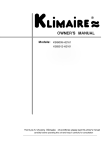
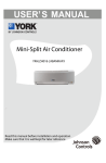
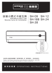
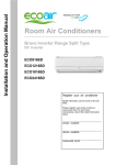
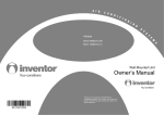
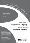
Models
Indoor Unit
MW09C1H
MW12C1H
Outdoor Unit
MR09C1H
MR12C1H
920-088-01
CONTENTS
Operation and maintenance
■ Notices for use ......................................1
■ Typical Unit Components ................................. 3
■Operation of remote controller ............................. 4
■Remote Control Instructions ............................ 7
■Routine Maintenance .................................11
■ Basic Troubleshooting ................................ 12
■ Service & Assistance ................................. 15
Installation service
■ installation ....... ................................16
■Typical Unit Dimensions .............................. 18
■ Install indoor unit ................................... 19
■ Install outdoor unit .................................. 21
■ Checklist ......................................... 22
This symbol stands for the items
should be forbidden.
This symbol stands for the items
should be followed
Thank you for choosing Friedrich Air Conditioning, please read this owner's manual
carefully before operating the unit and keep it carefully for consulation.
This appliance is not intended for use by persons (including children) with reduced
physic al, sensory or mental capabilities or lack of experience and knowledge,
unless they have been given supervision or instruction concerning use of the appliance
by a person reponsible for their safety.
Children should be supervised to ensure that they do not play with the appliance.
Do not dispose this product as unsorted municipal waste.
Collection of such waste separately for special treatment
is necessary.
Image shown in this operating instruction manual here is
indicative only. Actual product you receive may differ!
Congratulations
Thank you for your decision to purchase Friedrich. Your new Friedrich has been carefully engineered and manufactured to give you many years of dependable,
efficient operation, maintaining a comfortable temperature and humidity level. Many extra features have been built into your unit to assure quiet operation,
the greatest circulation of cool, dry air, and the most economic operation.
General Instructions
This Installation and Operation Manual has been designed to insure maximum satisfaction in the performance of your unit. For years of trouble-free service,
please follow the installation instructions closely. We cannot overemphasize the importance of proper installation.
and the controls are properly set, the unit may need service and
you should call your Friedrich service provider to check the unit.
WARNING
Refrigeration system
under high pressure
Do not puncture, heat, expose to flame or
incinerate.
Only certified refrigeration technicians should
service this equipment.
R410A systems operate at higher pressures
than R22 equipment. Appropriate safe
service and handling practices must be used.
Only use gauge sets designed for use with
R410A. Do not use standard R22 gauge sets.
Here are some suggestions to help you use your
new Friedrich most efficiently:
1.
Carefully read and follow the installation instructions.
2. Make sure the unit is the right capacity for the area being cooled.
An undersized unit makes the unit work too hard, using more
electricity than needed and increases wear. An oversized unit
will cycle on and off too rapidly, and therefore cannot control
humidity as well.
3. Clean the filter frequently (See Routine Maintenance, Page 27).
4.
Do not block the air flow to and from the unit.
5. A dirty filter or improperly set controls can affect the cooling
ability of the unit.
6. If cooling is weak and you have verified that the filter is clean
7.
Keep blinds, shades and drapes closed on the sunny side of the
room being cooled to reduce radiant heat.
8. Proper insulation helps your unit maintain the desired inside
temperature.
9. Whenever possible, shade south and west facing windows.
10. Keep window coverings away from the unit to provide free air flow.
WARNING
Read Installation Operation
Manual
Please read this manual thoroughly prior to
equipment installation or operation.
It is the installer’s responsibility to properly
apply and install the equipment. Installation
must be in conformance with the NFPA 70
-2008 National Electric Code or current edition,
International Mechanic Code 2009 or current
edition and any other applicable local or
national codes.
Failure to do so can result in property damage,
personal injury or death.
Your safety and the safety of others are very important.
We have provided many important safety messages in this manual and on your appliance. Always read and obey all
safety messages.
This is a safety Alert symbol.
This symbol alerts you to potential hazards that can kill or hurt you and others.
All safety messages will follow the safety alert symbol with the word “WARNING”
or “CAUTION”. These words mean:
A NIN
WARNING
Indicates a hazard which, if not avoided, can result in severe personal injury or
death and damage to product or other property.
CAUTION
Indicates a hazard which, if not avoided, can result in personal injury and
damage to product or other property.
All safety messages will tell you what the potential hazard is, tell you how to reduce the chance of injury, and tell you
what will happen if the instructions are not followed.
NOTICE
Indicates property damage can occur if instructions are not followed.
Notices for use
Working principle and special functions for cooling
Principle:
Air conditioner absorbs heat in the room and transmit to outdoor and discharged, so that
indoor ambient temperature decreased, its cooling capacity will increase or decrease by
outdoor ambient temperature.
Anti-freezing function:
If the unit is running in COOL mode and in low temperature, there will be frost formed on
the heat exchanger, when indoor heat exchanger temperature decreases below 32 º F, the
indoor unit microcomputer will stop compressor running and protect the unit.
Working principle and special functions for heating
Principle:
* Air conditioner absorbs heat from outdoor and transmits to indoor, in this way to increase
*
room temperature. This is the heat pump heating principle, its heating capacity will be
reduced due to outdoor temperature decrease.
If outdoor temperature becomes very low, please operate with other heating equipments.
Defrosting:
* When outdoor temperature is low but high humidity, after a long while running, frost will
*
*
*
form on outdoor unit, that will effect the heating effect, at this time, the auto defrosting
function will act, the heat running will stop for 8-10mins.
During the auto defrosting, the fan motors of indoor unit and outdoor unit will stop.
During the defrosting, the indoor indicator flashes, the outdoor unit may emit vapor.
This is due to the defrosting, it isn't malfunction.
After defrosting finished,the heating will recover automatically.
1
Notices for use
Anti-cool wind function:
In "Heat" mode, under the following three kinds of state, if indoor heat exchanger doesn't
arrive at certain temp., indoor fan will not start , in order to prevent cool wind blowing(within
2 mins):
1. Heating starts. 2.After Auto Defrost finished. 3.Heating under the low temperature.
Working temperature range
Indoor sideDB/WB( ºF)
Outdoor sideDB/WB( ºF)
Maximum cooling
95/75
115/86
Minimum cooling
70/59
70/-
Maximum heating
75/---
75/60
Minimum heating
68/---
5/-
The operating temperature range (outdoor temperature) for cooling unit is 32℉~115℉;
for cooling and heating unit is 5℉~115℉.
2
.
Typical Unit Components
Indoor unit
(Image shown here is indicative only. Actual product you receive may differ)
Front Panel
Air inlet
Display
Wrapping Tape
Filter
Guide panel
Wall Pipe
Air outlet
Wireless remote control
Display icon(Only for some Units):
Power/Run
Cooling
Heating
Set temp.
Receiver
Dehumidify
Outdoor unit
Connection pipe
Air in
Drainage hose
Air out
3
Operation of Remote Controller
START / STOP
1
Press to start or stop operation.
2
: Press to decrease temperature
setting.
3
: Press to increase temperature
setting.
FAN AUTO
4
Press to set fan speed.
MODE
5
Press to select operation mode
(AUTO/COOL/DRY/FAN/HEAT).
6
SENSOR
7
CLOCK
Press it set clock.
8
1
2
AIR SWEEP
9
4
8
7
Press it set swing angle.
5
6
TIMER ON
Press it to set auto-on timer.
3
9
10
11
12
13
14
15
10
EXTEND
11
TEMP
12
TIMER OFF
Press it to set auto-off timer
13
TURBO
14
SLEEP
15
LIGHT
Press it to turn on/off the light.
17
4
Operation of Remote Controller
26
27
25
24
23
22
16
17 18 19 20
16
17
MODE icon:
20
is displayed by pressing the
LIGHT button. Press LIGHT button
again to clear the display.
SLEEP icon :
is displayed by pressing "+"
and “-” buttons simultaneously. Press
them again to clear the display.
22
TEMP icon:
AIR SWEEP
LOCK icon:
SET TIME display:
After pressing TIMER button, ON or
Pressing TEMP button,
(indoor
(set temperature),
ambient temperature)
(outdoor ambient temperature)
and blank is displayed circularly.
19
LIGHT icon:
If MODE button is pressed,
current operation mode icon
(AUTO),
( COOL),
(DRY),
(FAN) or (HEAT
only for heat pump models) will show. 21
is displayed by pressing
the SLEEP button. Press this
button again to clear the display.
18
21
OFF will blink.This area will show
the set time.
23
icon:
is displayed when pressing
the AIR SWEEP button.
Press this button again to clear the 24
display.
TURBO icon:
is displayed when pressing the
TURBO button.Press this button
again to clear the display.
DIGITAL display:
This area will show the set temperature. In SAVE mode,"SE" will be
displayed. During defrosting operation, “H1” will be displayed.
5
Operation of Remote Controller
26
27
25
24
23
22
16
17 18 19 20
25
SENSOR icon:
27
is displayed when pressing the
SENSOR button. Press this button
again to clear the display.
26
21
EXTEND icon:
is displayed when pressing the
Press this button
again to clear the display.
EXTEND button.
FAN SPEED display:
Press FAN button to select the
desired fan speed setting (AUTO-
Low-Med-High).Your selection will
be displayed in the LCD windows,
except the AUTO fan speed.
6
Remote Control Instructions
Remote Controller Description
1 START / STOP :
Press this button to turn on the unit .Press this button again to turn off the unit.
2
Press this button to decrease set temperature. Hold it down for above 2 seconds to
rapidly decrease set temperature. In AUTO mode, set temperature is not adjustable.
3
:
Press this button to increase set temperature. Hold it down for above 2 seconds to
rapidly increase set temperature. In AUTO mode, set temperature is not adjustable.
4 FAN AUTO :
This button is used for setting Fan Speed in the sequence that goes from AUTO,
, then back to Auto.
, to
,
Auto
Low speed
Medium speed
High speed
5 MODE :
Each time you press this button, a mode is selected in a sequence that goes from AUTO,
COOL,DRY, FAN,and HEAT *, as the following:
FAN
HEAT *
COOL
AUTO
DRY
*Note: Only for models with heating function.
After energization, AUTO mode is defaulted. In AUTO mode, the set temperature will not
be displayed on the LCD, and the unit will automatically select the suitable operation
mode in accordance with the room temperature to make indoor room comfortable.
6
SENSOR :
Press this button to turn on SENSOR function. The unit automatically adjust temperature
according to the sensed temperature. Press this button again to cancel SENSOR function.
7 CLOCK :
Pressing CLOCK button,
blinks. Within 5 seconds, pressing + or - button adjusts the
present time. Holding down either button above 2 seconds increases or decreases the
time by 1 minute every 0.5 second and then by 10 minutes every 0.5 second. During
blinking after setting, press CLOCK button again to confirm the setting, and then
will be constantly displayed.
7
Remote Control Instructions
8 TIMER ON :
Press this button to initiate the auto-ON timer. To cancel the auto-timer program, simply
press this button again.
After pressing this button,
disappears and "ON "blinks. 00:00 is displayed for ON time
setting. Within 5 seconds, press + or - button to adjust the time value. Every press of either
button changes the time setting by 1 minute. Holding down either button rapidly changes the
time setting by 1 minute and then 10 minutes. Within 5 seconds after setting, press TIMER
ON button to confirm.
9 AIR SWEEP:
Press this button to set up & down swing angle, which circularly changes as below:
OFF
This remote controller is universal. If any command
the unit will carry out the command as
,
or
is sent out,
indicates the guide louver swings as:
10 EXTEND:
Pressing EXTEND button in COOL or DRY mode, the icon
is displayed and the indoor
fan will continue operation for 10 min utes in order to dry the indoor unit even though you
have turned off the unit.
After energization, EXTEND OFF is defaulted. EXTEND is not available in AUTO, FAN or
HEAT mode.
11 TEMP:
By pressing this button you can display the indoor setting temperature or indoor ambient
temperature.When the indoor unit is first powered on it will display the setting temperature,
if the temperature's display status is changed from other status to" ",displays the
ambient temperature, 5s later or within 5s, it receives other remote control signal that will
return to display the setting temperature. if the users haven't set up the temperature
displaying status,that will display the setting temperature.(This function is not applicable
for some models).
12 TIMER OFF :
Press this button to initiate the auto-off timer. To cancel the auto-timer program, simply
press the button again.TIMER OFF setting is the same as TIMER ON.
13 TURBO:
Press this button to activate / deactivate the Turbo function which enables the unit to
reach the preset temperature in the shortest time. In COOL mode, the unit will blow strong
cooling air at super high fan speed. In HEAT mode, the unit will blow strong heating air
at super high fan speed. (This function is not applicable for some models).
8
Remote Control Instructions
14
SLEEP:
Press this button to go into the SLEEP operation mode. Press it again to cancel this
function. This function is available in COOL or DRY mode to maintain the most
comfortable temperature for you.
15
LIGHT:
Press LIGHT button to turn on the display's light and press this button again to turn off
the display's light. If the light is turned on,
is displayed. If the light is tunrned off ,
disappears.
16 Combination of "+" and "-" buttons: About lock
Press "+ " and "-" buttons simultaneously to lock or unlock the keypad. If the remote
controller is locked,
is displayed. In this case, pressing any button,
blinks
three times.
17 Combination of "MODE" and "-" buttons: Allows you to toggle between Fahrenheit and Celsius.
When the unit is OFF, press "MODE " and "- " buttons simultaneously to switch between℃ and ℉ .
Replacement of Batteries
1.Remove the battery cover plate from the rear of the remote controller.
(As shown in the figure)
2.Take out the old batteries.
3.Insert two new AAA1.5V dry batteries, and pay attention to the polarity.
4. Reinstall the battery cover plate.
★ Notes:
●
When replacing the batteries, do not use old or different types of batteries,
●
If the remote controller will not be used for a long time, please
otherwise, it may cause malfunction.
remove batteries to prevent batteries from leaking.
●
The operation should be performed in its receiving range.
●
●
It should be kept 3 feet away from the TV set or stereo sound sets.
If the remote controller does not operate normally, please take the
batteries out and reinsert them after 30 seconds. If it still can't operate properly,
replace the batteries.
9
Sketch map for
replacing batteries
Front Panel Illumination On/Off
Display indicator light control of indoor unit
●
●
Display indicator light on: To turn 'On' the light function,the mark will
display on the remote controller screen by
pressing this button. In which case,the dissplayer indicator light will be on if the AC receives
this signal.
Display indicator light off: To turn 'Off ' the light function,the
will disappear
on the remote controller screen by pressing this
button. In which case, the display indicator light will
be off if the AC receives this signal.
Emergency operation
If the wireless remote control is lost
or broken, please use the manual switch
button. At this time, the unit will run in the
Auto mode, but the temperature and fan
speed cannot be changed. The operation
is shown below:
Manual switch
Open panel and the manual switch is on
the display box.
●
Turn on the unit: Press manual button and unit
will run in Auto mode immediately. The
microcomputer will adjust to the indoor
temperature to select (Cooling or Fan)
and obtain a comfortable setting.
●
Turn off the unit: Press manual switch to turn off unit.
10
Fig.3
Routine Maintenance
Caution
●
●
●
Turn power off and pull out the power plug before cleaning air conditioner, or it may cause electric
shock.
Never sprinkle water on the indoor unit and the outdoor unit for cleaning because it can cause an
electric shock.
Volatile liquid (e.g. thinner or gasoline) will damage the air conditioner. (So wipe the units with a
dry soft cloth, or a cloth slightly moistened with water or cleanser.)
Clean the front panel
When cleaning the front panel, please dip the cloth into the water temperature of 45℃ below, then to dry
the cloth and wipe the dirty part.
Note: Please do not to immerse the front panel in water, due to there are microcomputer components and
circuit diagrams on the front panel.
Clean the air filter (Recommended once every three months)
NOTE: If there is an excessive amount of dust around the air conditioner, the air filter should
be cleaned more frequently. Once filters are removed do not touch fins, edges may be
sharp. Failure to do so can result in minor to moderate personal injury.
① Take down the air filter
At the slot of surface panel to open an angle, pull the air filter
downward and take it out, please see the Fig. 4(a, b).
(a)
(b)
② Clean the air filter
To clean the dust adhering to the filters, you can either
use a vacuum cleaner, or wash them with warm water
the water with the neutral detergent should below 45
degree) ,and dry it in the shade.
NOTE: Never use water above 45℃ to clean, or it can
cause deformation or discoloration.
③ Insert the air filter
Reinsert the filters along the direction of arrowhead, and
then to cover the cover and clasp it.
11
Fig.4
Cause
●
●
●
●
●
●
The sound of water flow
during operation.
Turn unit on.
Raise/Lower temperature
setting.
Unit will resume normal
operation once power
has been restored.
Clean air filter.
Clean air conditioner.
Please contact an
Authorized Friedrich
Service Agency
When the compressor
starts or stops running
you may here a swoosh
or gugle, this isn't
a malfunction.
-
12
13
Cause
Immediately stop all operations and plug out, contact
the dealer in following situations occur.
There is harsh sound during operation.
The terrible odors emitted during operation.
Water is leaking in the room.
Air switch or protection switch often breaks.
Accidently splash water or something into unit.
There is an abnormal heat in power supply cord
and power plug.
14
Turn off unit and switch off breaker.
Service & Assistance
Troubleshooting" section and still need help, here is
a list of available services:
1
2
3
15
Installation
Important Notices
Indoor Unit Placement
1.The air inlet and outlet vent should be far from the obstruction, make sure that the air
can be blown through the whole room.
2.Select a position where the condensing water can be easily drained out, and the place
is easily connected for outdoor unit.
3.Select a location where the children can not reach.
4.Can select the place where is strong enough to withstand the full weight and vibration of
the unit. And will not increase the noise.
5.Be sure to leave enough space to allow access for routine maintenance. The height of the
installed location should be 8 ft or more from the floor.
6.Select a place about 3 ft or more away from TVset or any other electric appliances.
7.Select a place where the filter can be easily taken out.
8.Make sure that the indoor unit installation should accord with installation dimension
diagram requirements.
9.Do not use the unit in the immediate surroundings of a laundry a bath a shower or a
swimming pool.
Outdoor Unit Placement
1.Select a location from which noise and outflow air emitted by unit will not inconvenience
neighbors, animals, plants.
2.Select a location where there should be sufficient ventilation.
3.Select a location where there should be no obstructions cover the inlet and outlet vent.
4.The location should be able to withstand the full weight and vibration of the outdoor unit
and permit safe installation.
5.Select a dry place, but do not expose under the direct sunlight or strong wind.
6. Make sure that the outdoor unit installation dimension are in accordance with installation
dimension diagram, convenient for maintenance, repair.
7. The height difference of connecting the tubing within 16 ft , the length of connecting the
tubing within 33 ft.
8. Select a place where it is out of reach for the children.
9. Select a place where will not block the passage and do not influence the city appearance.
16
Installation
Safety Requirements For Electric Appliances
1. The power supply should be used the rated voltage and AC exclusive circuit,
the power cable diameter should be satisfied.
2. Don't damage power cord.
3. It should be reliably earthed, and it should be connected to the special earth device,
the installation work should be operated by the professional.
The air switch must have the functions of magnetic tripping and heat tripping, in order
to protect the short circuit and overloading.
4. The min. distance from the unit and combustive surface is 5 feet.
5. The appliance shall be installed in accordance with national wiring regulations.
6. An all-pole disconnection switch having a contact separation of at least 9 feet in all poles
should be connected in fixed wiring.
Note:
●
Make sure that the Live wire or Zero line as well as the earth wire in the family power
socket can not be wrong connected, there should be reliable and no short circuit in the
diagram.
●
wrong connection may cause fire.
Grounding requirements
1. Air conditioner needs to be properly grounded.
2. The yellow-green two-color wire in air conditioner is the grounding
wire and cannot be used for any other purpose. Do not cut.
17
Typical Unit Dimensions
Installation dimension diagram
Space to the ceiling
6 in
Above
Space to the wall
6 in Above
6 in Above
Space to the wall
10 ft
8 ft
Above
Air outlet side
Space to the floor
The dimensions of the space necessary for correct
installation of the appliance including the minimum
permissible distances to adjacent structures
Space to the obstruction
20 in Above
●
Above
12
12 in Above
t
e
ov
Ab
12 in
e
ov
Ab
Air outlet side
in
Space to the wall
Space to the wall
7f
Air inlet side
540
18
286
Above
Install indoor unit
Install the rear panel
1.Always mount the rear panel horizontally. Due to the water tray of indoor unit has been adopted the
both-way drainage design, the outlet of water tray should be adjusted slightly down when installing, that is
taking the outlet of the water tray as the center of a circle, the included angle between the evaporator and
level should be 0 or more, that is good for condensing water drainage.
Wall
2.Fix the rear panel on the wall with screws. Wall
Mark on the middle of it
Gradienter
Space
Space
(Where is pre-covered with plastic granula)
3.Be sure that the rear panel has been fixed
firmly enough to withstand the weight of an
adult of 60kg, further more, the weight should
be evenly shared by each screw.
to the
wall
to the
wall
above
above
6 in
6 in
Left
φ2 1/2 in
(Rear piping hole)
Right
φ2 1/2 in
(Rear piping hole)
Fig.5
Install the piping hole
Indoor
1.Make the piping hole (Ф 2 1/2) in the wall at a slight downward
slant to the outdoor side.
Wall pipe
Outdoor
Seal pad
2.Insert the piping-hole sleeve into the hole to prevent the connection piping
and wiring from being damaged when passing through the hole.
Ø55
Install the water drainage pipe
1.For well draining, the drain hose should be placed at a downward slant.
Wrenched
Bent
2.Do not wrench or bend the drain hose or flood its end by water.
3.When the long drainage hose passing through indoor,
should wrap the insulation materials.
Flooded
Connect indoor and outdoor electric wires
1.Open the surface panel.
2.Remove the wiring cover Fig 6.
3.Route the power connection cord and signal control wire (for cooling and heating unit only) from the
back of the indoor unit and pull it toward the front through the wiring hole for connection.
4.Reassemble the clampand wiring cover.
5.Recover the surface panel.
N(1) 2
BU
BK
3
BN YEGN
Fig.6
19
Install indoor unit
NOTE:
When connecting the electric wire if the wire length is not enough, please contact with
the authorized service shop to buy a exclusive electric wire that is long enough and the
joint on the wire are not allowed.
The electric wiring must be correctly connected, wrong connection may cause spare parts
malfunction.
● Tighten the terminal screw in order to prevent loose.
● After tighten the screw, slight pull the wire and confirm whether is it firm or not.
●
●
If the earth wire is wrong connection, that may cause electric shock.
● The
cover plate must be fixed, and tighten the connection wire, if it is poor installed, that
the dust, moisture may enter in or the connection terminal will be affected by outside force,
and will cause fire or electric shock.
Install the indoor unit
External connection
Gas side pipe
electric wire
The piping can be lead out from right, right rear, left
Liquid side piping
left rear.
1.When routing the piping and wiring from the left
Tailing 2
side piping
Tailing 1 Gas
or right side of indoor unit, cut off the tailings
Liquid side
insulation
Piping insulation
Finally
wrap it
from the chassis in necessary(Show in Fig.7)
Fig.7
Water
drainage
pipe
with tape
⑴ Cut off the tailings 1 when routing the wiring only;
⑵ Cut off the tailings 1 and tailings 2 when routing
both the wiring and piping.
Left
2.Take out the piping from body case, wrap the piping
右后
electric wire, water pipe with tape and pull them
Left rear
Right
through the piping hole (As show in Fig.8)
Fig.8
Right rear
3.Hange the mounting slots of the indoor unit on the
Fixing hook
Mounting
upper tabs of the rear panel and check if it is firm
baord
Mounting
enough.(As show in Fig.9)
plate
4.The height of the installed location should be 8 ft
or more from the floor.
Fig.9
5.The water drainage pipe can also be installed on the left of
the indoor-uint.
●
Install the connection pipe
1. Align the center of the piping flare with the relevant valve.
2.Screw in the flare nut by hand and then tighten the
nut with spanner and torque wrench refer to the
following:
Hex nut diameter
Tightening torque (lb . ft)
11~14.7
Ф6
22.8~25.8
Ф 9.52
36.9~40.6
Ф 12
44.3~47.9
Ф 16
51.6~55.3
Ф 19
Indoor unit piping
Spanner
Taper nut Piping
Torque
wrench
Note: First connect pipe to indoor unit, then to outdoor unit. Pay attention not to bending
piping as this may cause damage. Do not overtighten joint nut as this may cause
leakage.
20
Install outdoor unit
Electric wiring
1.Disassemble the cable cross plate sub-assy on the outdoor unit right side plate.
Cable Cross Plate sub-assy
2.Take off wire clamp. Connect and fix power connect
cord (for cooling and heating unit,connect and fix power
connect cord and signal control wire)to terminal of line
bank. Wiring should fit that of indoor unit.
3.Fix the power connection cable with wire clamp,
(for cooling and heating unit, use the wire clamp
to fix the power connection cable and the signal
control wire), then connect the corresponding
connector.
4.Ensure wire has been fixed well.
5.Install the cable cross plate sub-assy.
For 115V Uints
N(1) 2
BU
BK
N
L
3
BN BU YEGN
BN
L
N
Power
For 208~230V Uints
N(1) 2
BU
BK
3
BN
L1 L2
BN BU YEGN
L1 L2
Power
NOTE:
● Wrong wiring may cause spare parts malfunction.
● After the cable fixed, make sure there should be a free space between the connection
and connection and fixing place on the lead wire.
Air purging and leakage test
1. Connect charging hose of manifold valve to charge end of low pressure
valve (both high/low pressure valves must be tightly shut).
2. Connect joint of charging hose to vacuum pump.
Liquid pipe
3. Fully open handle handle of Lo manifold valve.
Gas pipe
4. Open the vacuum pump to evacuate. At the beginning, slightly
Valve
cap
loosen joint nut of low pressure valve to check if there
is air coming inside. (If noise of vacuum pump has
been changed, the reading of multimeter is 0) Then
tighten the nut.
5. Keep evacuating for more than 15mins and make
sure the reading of multi-meter is -1.0 10 5pa
(-76cmHg).
Vacuum
gauge
Vacuum pump
Fig. 10
6. Fully open high/low pressure valves.
7. Remove charging hose from charging end of low pressure valve.
8. Tighten bonnet of low-pressure valve. (As shown in Fig.10)
Condensate drainage of outdoor unit (no for cooling only)
The condensate and defrosting water formd during heating
in the outdoor unit can be properly discharged by drainage
pipe .
Installation method:set the drain connection in Ø 25 hole of the
chassis has been installed and then connect drainage pipe
with drain nozzle,so that condensate and defrosting waer can
be properly discharged
21
Chassis
Drain
connection
Checklist
Check after installation
Items to be checked
Possible malfunction
Has it been fixed firmly?
The unit may drop, shake or emit noise.
Have you done the refrigerant leakage test?
It may cause insufficient cooling(heating)
capacity
Is heat insulation sufficient?
It may cause condensation and dripping.
Is water drainage well?
It may cause condensation and dripping.
Is the voltage in accordance with the rated
voltage marked on the nameplate?
It may cause electric malfunction
or damage the part.
Is the electric wiring and piping
connection installed correctly and securely?
It may cause electric malfunction
or damage the part.
Has the unit been connected to a secure
earth connection?
It may cause electrical leakage.
Is the inlet and outlet been covered?
It may cause insufficient cooling(heating)
capacity.
Has the length of connection pipes
and refrigerant capacity been recorded?
The refrigerant capacity is not accurate.
Test Operation
1. Before test operation
(1)Do not switch on power before installation is completely finished.
(2)Electric wiring must be connected correctly and securely.
(3)Cut-off valves of the connection pipes should be opened.
(4)All the impurities such as scraps and thrums must be cleared from the unit.
2.Test operation method
(1)Switch on power, press "START / STOP" button on the wireless remote control
to start the operation.
(2)Press MODE button, to select the COOL, or/and FAN to check whether
the operation is normal or not.
22
Friedrich Air Conditioning Co.
10001 Reunion Place, Suite 500 • San Antonio, Texas 78216
1.800.541.6645
www.friedrich.com
66129907272