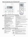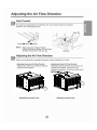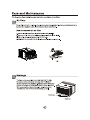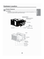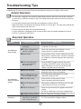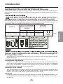
1
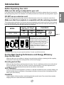
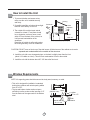
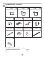
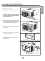
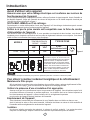
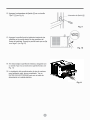
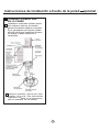
F hr Fan Speed Money Fan Cool Saver ® Only Dry Timer 0n0ff CP06 Mode Auto Swing Temp Power CP08 F F hr hr Fan Fan Speed Speed Money Fan Cool Fan Cool Money Saver®® Only Only Saver Dry Dry Timer Timer 0n0ff 0ff 0n 200 Mode Mode Auto Auto Swing Swing Temp Temp Power Power Congratulations! Thank you for choosing Friedrich. Your Friedrich unit is designed for maximum comfort and quietness. Table of Contents Introduction ..................................................................................2 Safety Precautions.......................................................................3 How to operate your Friedrich ...................................................5 Adjusting the Air Flow Direction.................................................6 Care and Maintenance .................................................................7 Hardware Location .......................................................................8 Installation Instructions..........................................................9 Troubleshooting Tips .................................................................17 Warranty ......................................................................................18 Introduction Before Operating Your Unit Make sure the wiring is adequate for your unit. If you have fuses, they should be of the time delay type. Before you install or relocate this unit, be sure that the amperage rating of the circuit breaker or time delay fuse does not exceed the amp rating listed in figure 1. DO NOT use an extension cord. The cord provided will carry the proper amount of electrical power to the unit; an extension cord will not. Make sure that the receptacle is compatible with the wall plug provided. This insures proper grounding. If you have a two-prong receptacle you will need to have the circuit replaced by a certified electrician with a grounded circuit that meets all national and local codes and ordinances. You must use the three-prong plug furnished with the air conditioner. 115V~ 15 230V~ 125 NEMA NO. 5-15P Figure 1 Power cord may include a current interrupter device. A test and reset button is provided on the plug case. The device should be tested on a periodic basis by first pressing the TEST button and then the RESET button. If the TEST button does not trip or if the RESET button will not stay engaged, discontinue use of the air conditioner and contact a qualified service technician. N OT E Aluminum house wiring may pose special problems. Consult a qualified electrician. For the Best Cooling Performance and Energy Efficiency Keep the filter clean Make sure that your air conditioner is always in top performing condition by cleaning the filter regularly. Instructions for removing and cleaning the filter can be found on page 7. Provide good air flow Make sure that the airflow to and from the unit is clear. Your air conditioner puts the air out at the side of the unit, and takes in air at the left. Airflow is critical for good operation. It is just as important on the outside of the building that the airflow around the unit exterior is not blocked. Unit Placement If your air conditioner can be placed in a window or a wall that is shaded by a tree or another building, the unit will operate even more efficiently. Using drapes or blinds on the sunny side of the dwelling will also add to your unit's efficiency. Insulation Good insulation will be a big help in maintaining desirable comfort levels. Doors should have weather stripping. Be sure to caulk around doors and windows. 2 E CP08 PLUG FACE N CP06 G MODEL CIRCUIT RATING OR TIME DELAY FUSE AMP VOLT For inner cleaning, contact an Authorized Service Center or a dealer. Do not use harsh detergent that causes corrosion or damage on the unit. Harsh detergent may also cause failure of product, fire, or electronic shock. 24 24 H Installation Instructions Read these instructions completely and carefully. ❒ Phillips-head screwdriver ❒ Flat-blade screwdriver ❒ Ruler or tape measure ❒ Scissors or knife ❒ Pencil ❒ Level ❒ Hammer Before You Begin NOTE TO INSTALLER: Leave these instructions with the air conditioner after installation is complete. CAUTION: Do not under any circumstances, cut or remove the third (ground) prong from the power cord. Do not change the plug on the power cord of this air conditioner. NOTE TO CONSUMER: Keep this Installation and Operation Manual for future use. Aluminum house wiring may present special problems ; consult a qualified electrician. Important notes: It is recommended that proper attire be worn during installation. For personal safety, this air conditioner must be properly grounded. It is important to have the wall outlet and circuit checked by a qualified electrician if there is any doubt as to whether a proper ground exists. 9 ENGLISH Tools You Will Need How to Install the Unit Fence Awning Cooled air 2. If possible Install the unit where the sunlight does not shine directly on the unit. 30"~60" 3. The outside of the cabinet must extend outward for at least 12" and there should be no obstacles, such as a fence or wall, within 20" from the back of the cabinet, as it will prevent heat radiation of the condenser. Restriction of outside air will greatly reduce the cooling efficiency of the air conditioner. Heat radiation About 1/2" Over 20" CAUTION: DO NOT cover or block any of the side louvers. All side louvers of the cabinet must remain exposed and unobstructed to the outside of the structure. 4. Install the unit with a rear, downward slope, so the back is slightly lower than the front (about 1/4" bubble on a level). This will force condensation to flow to the outside. 5. Install the unit with the bottom about 30"- 60" above the floor level. Window Requirements NOTE: All supporting parts should be secured to sturdy wood, masonry, or metal. • This unit is designed for installation in standard double hung windows with actual opening widths from 22" to 36". • The top and bottom window sash must open sufficiently to allow a clear vertical opening of 15" from the bottom of the upper sash to the window stool. 22" to 36" 15" min (With frame curtain) Stool Offset 1 /2" to 11/4" Sill Interior wall 20 1/12" min. (Without frame curtain) 10 Exterior ENGLISH 1. To prevent vibration and excess noise, make sure the unit is installed securely and firmly. Installation Kit Contents Type A:13EA (SCREW) Type B:3EA (SCREW) 4 Type E:2EA (FRAME CURTAIN) 5 3 16mm 10mm Type D:2EA (NUT) Type C:5EA (SCREW) 2 16mm 1 Type F:2EA (SILL SUPPORT) 6 Type G:2EA (BOLT) 7 10mm Type H:1EA (FOAM-STRIP) 8 Type K:2EA (FRAME-GUIDE) 9 10 Type L:1EA (WINDOWLOCKINGBRACKET) Type N:1EA 12 (DRAIN JOINT PIPE) Have the following tools available for installation: * Screwdriver (Slotted and Phillips) * Knife * Pencil * Ruler * Hammer * Level 11 Type M:1EA (FOAM-PE) 11 Suggested Tool Requirements SCREWDRIVER(+, -), RULER, KNIFE, HAMMER, PENCIL, LEVEL 2. Slide the unit out from the cabinet by gripping the base pan handle and pulling forward while bracing the cabinet. (Fig.2) Fan Speed 0 F hr Money Saver ® Timer 0n/0ff Fan Only Cool Dry Temp Auto Swing Mode Powe r Fig. 1 3. Cut the window sash seal to the proper length. Peel off the backing and attach the Foam-PE to the underside of the window sash. (Fig.3) 4. Insert the Frame guides into the bottom of the cabinet. (Fig.4) Fan Speed 0 F hr Money Saver ® Timer 0n/0ff Fan Only Cool Dry Temp Auto Swing Mode Powe r Fig. 2 5. Insert the Frame Curtain into the Upper Guide and Frame Guides.(Fig.4) 6. Fasten the curtains to the unit with 8 Type A screws. (Fig.4) Foam-PE Fig. 3 Upper guide Screw (Type A) 1 Screw(Type A) 1 Frame guide 12 9 Fig. 4 ENGLISH Shipping screws PREPARATION OF CHASSIS 1. Remove the screws which fasten the cabinet at both sides and at the back. (Fig.1) Cabinet Installation 1. Open the window. Mark a line on center of the window stool.Carefully place the cabinet on the window stool and align the center mark on the bottom front with the center line marked in the window stool. (Fig. 1) Upper Guide Window stool Front Angle 2. Pull the bottom window sash down behind the Upper Guide until they meet. (Fig. 2) NOTE: Do not pull the window sash down so tightly that the movement of Frame Curtain is restricted. Window Sash Fig. 1 Upper guide Foam-PE 11 Cabinet Frame Curtain Foam-PE Fig. 2 3. Loosely assemble the Sill Support using the parts . (Fig. 3) INDOOR OUTDOOR Sill Support Bolt Nut Fig. 3 4. Select the position that will place the Sill Support near the outer most point on sill. (Fig. 4) Screw(Type A) About 1/2" Frame Guide NOTE: Be careful when you install the cabinet (Frame Guides are broken easily). 5. Attach the Sill Support to the cabinet track hole in relation to the selected position using 2 -type A screws in each support. ( Fig. 4). 13 Cabinet INDOOR OUTDOOR Fig. 4 6. The cabinet should be installed with a very slight tilt (about 1/2") downward toward the outside (See Fig. 5). Adjust the bolt and the nut of Sill Support 6 for balancing the cabinet. About 1/2" Screw(Type B) 2 Sill Support 6 7. Attach the cabinet to the window stool by driving the screws 2 [Type B: Length 16mm (5/8 inch) and below.] through the front angle into window stool. (Fig. 5) Sash track 8. Pull each Frame Curtain 5 to each window sash track, and repeat step 2. (Fig. 5) Front Angle Screw(Type B) 2 Sill Support 6 Fig. 5 9. Attach each Frame Curtain 5 to the window sash using screws 3 (Type C). ( Fig. 6) CAUTION: Do not drill a hole in the bottom pan. The unit is designed to operate with approximately 1/2" of water in bottom of pan. There is no need to add water if the pan is dry. Type C 3 Fig. 6 10. Slide the unit into the cabinet. ( Fig. 7) CAUTION: For security purposeV, reinstall the 2 screws (Type A) at cabinet's side, that were removed in step 1 on page 12. Fan Speed Power cord 0 F hr Money Saver ® Timer 0n/0ff Fan Only Cool Dry Temp Auto Swing Mode Power Screw(Type A) 1 Screw(Type A) 1 Fig. 7 11. Cut the Foam-Strip to the proper length (window width) and wedge between the upper window sash and the lower window sash. ( Fig. 8) Foam-Strip Fig. 8 14 Fig.11 Through-the-Wall Installation Instructions-Optional The case may be installed through-the-wall in both existing and new construction. 1 IMPORTANT (cont.) D Secure with 14 wood screws anchored at Read completely, then follow step-by-step. NOTE: Obtain all materials locally for mounting the air conditioner through the-wall. Ieast an inch into the wall support structure. NOTE: Drill pilot holes, if necessary, for proper installation. If the frame is oversized, use shims to prevent case distortion. 1 IMPORTANT 2 FINISH THE WALL OPENING A Caulk all four sides on the outdoor side of Through-the-wall installation is not appropriate if any of the side or top louvers in the case will be obstructed by the wall. the case to prevent moisture from getting through to the interior wall. Use of flashing (drip rail) will further prevent water from dripping inside the wall and down the outsida of the building. All side and top louvers in the case must project on the outdoor side of the wall. The room side of the case must project into the room far enough to maximize the balance of the unit. The case must be installed level from sideto side and with a slight tilt from front to rear. Use a level; no more than a 1/2 bubble will be the correct case slant to the outside. Lintel angle is required to support bricks or blocks above opening. Flashing is required and should extend the length of the opening to ensure no inside cavity leakage occurs. A Remove the air conditioner from the case. For specific instruction, refer to the Window Installation Instructions. B Make certain that a wall receptacle is available close to the hole location or make arrangementsto install a receptacle. C Place the case in the wall opening and place wood support strips between the case bottom and the flashing on both sides of the bottom rail. They should be the same height as the bottom rail and the same length as the wall opening. B Place the air conditioner into the case. For specific instruction, refer to the Window Installation Instructions. 16 Troubleshooting Tips Troubleshooting Tips save time and money! Review the chart below first and you may not need to call for service. Normal Operation • You may hear a pinging noise caused by water being picked up and thrown against the condenser on rainy days or when the humidity is high. This design feature helps remove moisture and improve efficiency. • You may hear the thermostat click when the compressor cycles on and off. • Water will collect in the base pan during high humidity or on rainy days. The water may overflow and drip from the outdoor side of the unit. • The fan may run even when the compressor does not. • Your air conditioner is designed to cool in warm weather when the outside temperature is above 60°F(16°C) and below 1°F(4°C). Abnormal Operation Problem Air conditioner does not start Air conditioner does not cool as it should Air conditioner freezing up Possible Causes What To Do ƵThe air conditioner is unplugged. • Make sure the air conditioner plug is pushed completely into the outlet. ƵThe fuse is blown/circuit breaker is tripped. • Check the house fuse/circuit breaker box and replace the fuse or reset the breaker. ƵPower failure. • If power failure occurs, turn the mode control to Off. When power is restored, wait 3 minutes to restart the air conditioner to prevent tripping of the compressor overload. ƵThe current interrupter device was tripped on the power cord. • Press the RESET button located on the power cord plug. If the RESET button will not stay eng aged, discontinue use of the air conditioner and contact a qualified service technician. ƵAirflow is restricted. • Make sure there are no curtains, blinds, or furniture blocking the front of the air conditioner. ƵThe THERMOSTAT may not be set high enough. • Push temperature setting button to coolest temperature setting of 60°F. ƵThe air filter is dirty. • Clean the filter at least every 2 weeks. See the operating instructions section. ƵThe room may have been hot. • When the air conditioner is first turned on you need to allow time for the room to cool down. ƵCold air is escaping. • Check for open furnace floor registers and cold air returns. • Set the air conditioner's vent to the closed position. ƵCooling coils have iced up. • See Air Conditioner Freezing Up below. ƵIce blocks the air flow and stops the air conditioner from cooling the room. • Set the mode control on high fan until the ice thaws out. This may indicate a bigger problem. 17 Friedrich Air Conditioning Company 10001 Reunion Place, Suite 500 San Antonio, TX 78216 800.541.6645 www.friedrich.com ROOM AIR CONDITIONERS LIMITED WARRANTY FIRST YEAR ANY PART: If any part supplied by FRIEDRICH fails because of a defect in workmanship or material within twelve months from date of original purchase, FRIEDRICH will repair the product at no charge, provided room air conditioner is reasonably accessible for service. Any additional labor cost for removing inaccessible units and/or charges for mileage related to travel by a Service Agency that exceeds 25 miles one way will be the responsibility of the owner. This remedy is expressly agreed to be the exclusive remedy within twelve months from the date of the original purchase. SECOND THROUGH FIFTH YEAR SEALED REFRIGERANT SYSTEM: If the Sealed Refrigeration System (defined for this purpose as the compressor, condenser coil, evaporator coil, reversing valve, check valve, capillary, filter drier, and all interconnecting tubing) supplied by FRIEDRICH in your Room Air Conditioner fails because of a defect in workmanship or material within sixty months from date of purchase, FRIEDRICH will pay a labor allowance and parts necessary to repair the Sealed Refrigeration System; PROVIDED FRIEDRICH will not pay the cost of diagnosis of the problem, removal, freight charges, and transportation of the air conditioner to and from the Service Agency, and the reinstallation charges associated with repair of the Sealed Refrigeration System. All such cost will be the sole responsibility of the owner. This remedy is expressly agreed to be the exclusive remedy within sixty months from the date of the original purchase. APPLICABILITY AND LIMITATIONS: This warranty is applicable only to units retained within the Fifty States of the U.S.A., District of Columbia, and Canada. This warranty is not applicable to: 1. 2. 3. Air filters, fuses, batteries and the front grille removal tool. Products on which the model and serial numbers have been removed. Products which have defects or damage which results from improper installation, wiring, electrical current characteristics, or maintenance; or caused by accident, misuse or abuse, fire, flood, alterations and/or misapplication of the product and/or units installed in a corrosive atmosphere, default or delay in performance caused by war, government restrictions or restraints, strikes, material shortages beyond the control of FRIEDRICH, or acts of God. OBTAINING WARRANTY PERFORMANCE: Service will be provided by the FRIEDRICH Authorized Dealer or Service Organization in your area. They are listed in the Yellow Pages. If assistance is required in obtaining warranty performance, write to: Friedrich Air Conditioning Co.,ATTN:Warranty Registration,10001 Reunion Place,Ste.500,San Antonio,TX 78216. LIMITATIONS: THIS WARRANTY IS GIVEN IN LIEU OF ALL OTHER WARRANTIES. Anything in the warranty notwithstanding, ANY IMPLIED WARRANTIES OF FITNESS FOR PARTICULAR PURPOSE AND/OR MERCHANTABILITY SHALL BE LIMITED TO THE DURATION OF THIS EXPRESS WARRANTY. MANUFACTURER EXPRESSLY DISCLAIMS AND EXCLUDES ANY LIABILITY FOR CONSEQUENTIAL OR INCIDENTAL DAMAGE FOR BREACH OF ANY EXPRESSED OR IMPLIED WARRANTY. Performance of Friedrich’s Warranty obligation is limited to one of the following methods: 1. Repair of the unit 2. A refund to the customer for the prorated value of the unit based upon the remaining warranty period of the unit. 3. Providing a replacement unit of equal value The method of fulfillment of the warranty obligation is at the sole discretion of Friedrich Air Conditioning. NOTE: Some states do not allow limitations on how long an implied warranty lasts, or do not allow the limitation or exclusion of consequential or incidental damages, so the foregoing exclusions and limitations may not apply to you. OTHER: This warranty gives you specific legal rights, and you may also have other rights which vary from state to state. PROOF OF PURCHASE: Owner must provide proof of purchase in order to receive any warranty related services. All service calls for explaining the operation of this product will be the sole responsibility of the consumer. All warranty service must be provided by an Authorized FRIEDRICH Service Agency, unless authorized by FRIEDRICH prior to repairs being made. (11-10) 18 FRANÇAIS Manuel d'utilisation et d'installation de votre climatiseur de pièce F hr Fan Speed Money Fan Cool Saver ® Only Dry Timer 0n0ff 115 Volts CP06 Mode Auto Swing Temp Power CP08 Enregistrement de votre climatiseur de pièce Vous trouverez l'information concernant l'appareil sur la plaque signalétique située sur le côté de l'appareil, près du panneau de commande. Veuillez remplir et poster la carte d'enregistrement fournie avec l'appareil ou enregistrez-vous en ligne à www.friedrich.com (USA uniquement). Veuillez consigner l'information à l'emplacement ci-dessous pour référence ultérieure. F F hr hr Fan Fan Speed Speed Money Fan Cool Fan Cool Money Saver®® Only Only Saver Dry Dry Timer Timer 0n0ff 0ff 0n NUMÉRO DU MODÈLE 920-200-00 (10/10) NUMÉRO DE SÉRIE DATE D'ACHAT Mode Mode Auto Auto Swing Swing Temp Temp Power Power Félicitations! Merci d'avoir choisi Friedrich. Votre unité Friedrich est conçue pour vous offrir le confort et le silence maximums. Table des matières Introduction ..................................................................................2 Mesures de sécurité.....................................................................3 Fonctionnement de la télécommande........................................5 Réglage de l'orientation du débit d'air .......................................6 Soins et entretien .........................................................................7 Installation du matériel ................................................................8 Guide d'installation ......................................................................9 Problèmes fréquents et solutions ............................................17 Garantie.......................................................................................18 Introduction Avant d'utiliser votre appareil Assurez-vous que votre câblage électrique est conforme aux normes de fonctionnement de l'appareil. Si votre système électrique comporte des fusibles, veillez qu'ils soient de type temporisé. Avant d'installer ou de déplacer l'appareil, veillez que l'intensité de courant du disjoncteur ou du fusible temporisé n'excède pas l'intensité de courant spécifiée à la figure 1. N'UTILISEZ JAMAIS un fil de rallonge. Contrairement au cordon d'alimentation fourni avec l'appareil, le fil de rallonge n'acheminera pas le courant d'alimentation approprié au bon fonctionnement de l'appareil. Cela assure la mise à la terre appropriée. Si vous possédez un réceptacle à deux broches, vous devrez le remplacer par un réceptacle conforme à tous les codes et règlements nationaux ou municipaux. Vous devez utiliser la fiche à trois broches fournie avec votre climatiseur. MODÈLE CP06 CP08 VALEUR NOMINALE OU TEMPORISATION DU CIRCUIT FUSIBLE TYPE DE FICHE AMP VOLT NO. NEMA (National Electrical Manufacturers Association) 15 125 5-15P 115V~ 230V~ Figure 1 Le cordon d'alimentation peut inclure un dispositif de coupure. Un bouton Test et un bouton Reset (rétablir) sont fournis dans le boîtier de la fiche. Ce dispositif doit être périodiquement testé en appuyant d'abord sur le bouton TEST et ensuite sur le bouton RESET. Si le bouton TEST ne déclenche pas ou que le bouton RESET ne reste pas activé, veuillez suspendre l'utilisation du climatiseur et contacter un technicien AVIS Une installation électrique en aluminium peut poser des problèmes particuliers. Consultez un électricien qualifié. Pour obtenir le meilleur rendement énergétique et de refroidissement Maintenez le filtre propre Afin de maintenir le rendement de votre climatiseur à son meilleur niveau, nettoyez régulièrement le filtre. Reportez-vous à la page 7 pour les instructions de dépose et de nettoyage du filtre. Veillez à la présence d'une circulation d'air appropriée. Assurez-vous que l'air circule librement vers et en provenance de l'appareil. Votre climatiseur aspire l'air à sa surface inférieure et l'évacue à sa surface supérieure. La circulation d'air est un facteur important au bon fonctionnement de l'appareil. La libre circulation de l'air est également importante pour la portion de l'appareil située à l'extérieur de l'immeuble. Emplacement de l'appareil Votre climatiseur fonctionnera plus efficacement si vous l'installez dans une fenêtre ou dans un mur situé à l'ombre d'un arbre ou d'un autre immeuble. L'utilisation de rideaux ou stores du côté ensoleillé de l'immeuble améliorera également le rendement de l'appareil. Isolation Une bonne isolation permettra de maintenir le niveau de confort souhaité. Les portes devraient comporter un calfeutrage adéquat. Veillez à bien calfeutrer le périmètre des portes et fenêtres. 2 FRANÇAIS Veillez à ce que la prise murale soit compatible avec la fiche du cordon d'alimentation de l'appareil. Mesures de Sécurité Pour éviter des accidents corporels ou des dommages matériels, suivez ces instructions. ƵUn mauvais fonctionnement dû à l’ignorance de ces instructions peut provoquer des préjudices corporels ou des dommages. AVERTISSEMENT Ce symbole signale un risque de blessure grave, voire mortelle. ATTENTION Ce symbole signale un risque limité aux dommages matériels. Ƶ Les significations respectives des symboles utilisés dans ce manuel sont indiquées ci-dessous. Ne faites jamais cela Faites toujours cela Pour le nettoyage de l’intérieur, veuillez contacter un Centre de Service Agrée ou un concessionnaire. N’utilisez pas de détergent puissants qui provoquent la corrosion ou endommagent l’unité. Les détergents puissants peuvent aussi provoquer des pannes, des incendies ou des chocs électriques. 3 ATTENTION Lorsque le filtre à air doit être retiré, ne pas toucher les parties métalliques de l'appareil. Ne pas nettoyer le climatiseur avec de l'eau. Quand l'unité devrait être nettoyée, change l'unité de, et le débrancher. / HDXSHXWV LQILOWUHUGDQV O DSSDUHLOHWDIIHFWHUO LVROHPHQW &HODSHXWpJDOHPHQWSURYRTXHU XQFKRFpOHFWULTXH /e YHQWLODWHXr de UHIURLGLVVHPHQW WRXUQDQW jJUDQGHYLWHVVHGDQV O DSSDUHLOFHODSHXWSURYRTXHUXQ DFFLGHQW Ne pas opérer l'unité sans le filtre à air ou quand le grillage frontal a été enlevé. Ne pas placer une plante d'intérieur ou un animal domestique près de l'appareil en risquant de l'exposer directement à l'air froid. Ne pas se servir de l'appareil à des fins spéciales. De lD SRXVViqUHSRXUUDLW V DFFXPXOHUVXUO pFKDQJHXU WKHUPLTXH 噝&HSURGXLWSHXWEOHVVHUOHV DQLPDX[RXDELPHUOHVSODQWHV /HFOLPDWLVHXUQHGRLWSDV rWUHXWLOLspSRXU SURWpJHUFHUWDLQVDSSDUHLOVGHSrpFLVLRQGHV DOLPHQWVGHVDQLPDX[GHVSODQWHVHWGHV REMHWVG DUW/DTXDOLWpULVTXHG HQVRXIIULU Ne pas actionner les dispositifs de commande les mains mouillées. Ne pas utiliser d'insecticide à proximité de l'appareil ni de produits inflammables. BORDS POINTUS! Les bords du cas peuvent être pointus! ,O\DULVTXHGHFKRF pOHFWULTXH / DSSDUHLOULVTXHGHSUHQGUHIHX RXOHFRIIUHWULVTXHG rWUH GpIRUPp )DLWHVDWWHQWLRQHQPDQLSXODQWOHEovWLHU 6DLVLVVH]OHEovWLHUIHUPHPHQWHWQHOH ODLVVH]SDVJOLVVHUWRXWHQOHWHQDQW (PSOR\H]OHVJDQWVORXUGVSRXUPDQLSXOHU le bovWLHUDXEHVRLQ 1HODLVVH]SDV le bovWLHU JOLVVHUFRQWUH YRWUHSHDX 噝 Vous risquez de vous blesser. )5$1嘦$,6 4 24 24 9 Installation de lÿ appareil 1. Installez l'appareil solidement et sécuritairement de manière à prévenir la présence de vibrations et bruits. 2. Clôture Auvent Air refroidi 30"~60" Environ 1/2" (1,27 cm) 20" (51 cm) ou plus MISE EN GARDE : Attention : tous les louvres latéraux du boîtier doivent restés ouverts et non bouchés vers lÿ extérieur de la structure. 4. Installez l’unité avec une inclinaison arrière vers le bas pour que l’arrière soit légèrement plus bas que l’avant d’environ. Cela force la condensation à couler vers l’extérieur. 5. Installez l'appareil de manière à ce que sa surface inférieure se situe entre 30" et 60" (76 et 152 cm) au-desssus du niveau du plancher. Dimensions de fenêtre minimales NOTE : Tous les éléments d'installation doivent être fixés à du bois, de la maçonnerie ou du métal sain et solide. • Cet appareil est conçu pour installation dans des fenêtres à guillotine normales de largeur variant entre 22" et 36". • Les châssis supérieur et inférieur de la fenêtre doivent offrir une ouverture verticale d'au moins 15" entre le bas du châssis supérieur et le rebord de la fenêtre. 22" à 36" 15"min. Rebord (volet d'étanchéité inclus) Décalage 1 /2" to 11/4" Seuil Mur intérieur 20 112" min. (Sans volets d'étanchéité 10 Extérieur FRANÇAIS 3. Le boîtier doit sortir d'au moins 12" à l'extérieur et aucun obstacle du genre clôture ou mur doit se situer à moins de 20" de l'arrière du boîtier car cela nuira à la radiation de chaleur du condenseur. La capacité de refroidissement du climatiseur sera sérieusement affectée par une restriction d'alimentation d'air extérieur. Radiation de chaleur Contenu du nécessaire d’installation Tipo B:3 EA ( TORNILLO) 4 Tipo C:5 EA (TORNILLO) 3 16mm Tipo D:2 EA (TUERCA) 2 16mm 1 Tipo E:2 EA Tipo F:2 EA 6 5 (SOPORTE DE ALFÉIZAR) (PANEL GUÍA) Tipo G:2 EA (TORNILLO) 10mm Tipo A:13 EA (TORNILLO) 7 10mm Tipo H:1 EA 8 (TIRA DE GOMA) Tipo L:1 EA 10 Tipo K:2 EA 9 (GUÍA MARCO) (CHAPADE SOPORTEPARALAVENTANA) Tipo M:1 EA 11 (BANDA ADHESIVA) Tipo N:1 EA 12 (TAPA DEL DESAGÜE) Para la instalación debería tener a disposición los instrumentos siguientes: * Destornillador (Estrella y Phillips) * Cucjillo * Lápiz Nivel * Regla * Martillo 11 Outils recommandés TOURNEVIS (+, -), RÈGLE, COUTEAU, MARTEAU, CRAYON, NIVEAU PRÉPARATION DU CADRE 1. Déposez les vis situées de part et d'autre et à l'arrière du boîtier. (Fig 1) Vis d'expédition Fan Speed FRANÇAIS 2. Tout en retenant le boîtier, glissez l'appareil hors du boîtier en tirant vers l'avant sur la poignée du réceptacle d'eau. (Fig 2) 0 F hr Money Saver ® Timer 0n/0ff Fan Only Cool Dry Temp Auto Swing Mode Powe r Fig. 1 3. Corte la banda adhesiva ycoló quela del ancho de la ventana. Remueva el plástico de la banda adhesiva y colóquela en la parte superior de el marco inferior de la ventana. 4 Fan Speed 0 F 0 F hr Money Saver ® Timer 0n/0ff Fan Only Cool Dry Temp Auto Swing Mode Powe r (Fig 4) Fig. 2 5. Insérez les volets d'étanchéité dans le rail de guidage supérieur et dans les dispositifs de guidage du cadre. (Fig 4) (FENÊTRE) Fig. 3 RAIL DE GUIDAGE SUP RIEUR VIS 1 6. Fixez les volets d'étanchéité à l'appareil à l'aide de quatre vis de type A . (Fig 4) (type A) VIS (Type A) 1 DISPOSITIF DE GUIDAGE DU CADRE Fig. 4 12 Installation du boîtier 1. Ouvrez la fenêtre. Tracez une ligne au centre du rebord de fenêtre. Placez le boîtier soigneusement sur le rebord de fenêtre et alignez le repère central de sa portion inférieure avant avec la ligne tracée sur le rebord de fenêtre. (Fig. 1) 2. Abaissez le châssis inférieur à l'arrière du rail de guidage supérieur jusqu'à ce qu'ils fassent (Fig. 2) Rail de guidage supérieur Rebord de fenêtre Angle avant Fig. 1 Châssis de fenêtre Rail de guidage supérieur Joint d'étanchéité en mousse 11 NOTE: Ne serrez pas le châssis de fenmtre au point où cela nuira au mouvement des volets d'étanchéité. 5 Boîtier Volet d'étanchéité 5 Joint d'étanchéité en mousse Fig. 2 3. Assemblez le support de seuil 6 à l'aide des pièces illustrées dans la fig. 3 mais ne les INTÉRIEUR serrez pas. (Fig. 3) EXTÉRIEUR Support de seuil Boulon Écrou 7 6 4 Fig. 3 NOTE : Installez le boîtier avec précaution (les dispositifs de guidage de cadre peuvent briser). Dispositif de guidage de cadre Vis (Type A) 1 9 9 Boîtier 5. Fixez les supports de seuil 6 aux orifices de guidage du boîtier, en fonction de l'emplacement sélectionné, à l'aide de 2 vis de type A pour chaque support(Fig. 4). 13 INTÉRIEUR Environ 1/2" (1,27 cm) 4. Choisissez l'emplacement qui situera le support de seuil 6 à l'emplacement le plus à l'extérieur du seuil (Fig. 4). EXTÉRIEUR Fig. 4 6. Installez le boîtier avec une inclinaison d'environ 1/2" (1,27 cm) vers l'extérieur (Voyez la fig. 5). Réglez l'écrou et le boulon des supports de seuil 6 de manière à équilibrer le boîtier. 2 Environ 1/2" Vis (Type B) Support de seuil 7. Fixez le boîtier au rebord de fenêtre à l'aide de vis de type B 2 (16 mm [5/5"] de long) passant à travers de l'angle avant du boîtier et se logeant dans le rebord de fenêtre. 6 Coulisse de chassis FRANÇAIS 8. Tirez chaque volet d'étanchéité entièrement contre chaque coulisse de châssis et répétez l'étape 2. (Fig. 5) Angle avant Vis (Type B) Support de seuil 2 6 Fig. 5 9. Fixez chaque volet d'étanchéité à la coulisse de châssis à l'aide de vis de typeC. Vis C (Fig. 6) MISE EN GARDE : Ne percez pas de trous dans le réceptacle d'eau. L'appareil est conçu pour fonctionner avec environ 1/2" (1,27 cm) d'eau présent dans le réceptacle d'eau. S'il n'y a pas d'eau dans le réceptacle, il n'est pas nécessaire d'en ajouter. Fig. 6 10. Glissez l'appareil dans le boîtier. (Fig. 7) ATTENTION : Pour votre sécurité, réinstallez le 2 (type A) qui avait été enlevé à l’étape 1 de la page 12, sur le côté du boîtier. Fan Speed 0 F hr Money Saver ® Timer 0n/0ff Fan Only Cool Dry Temp Auto Swing Mode Power Vis (Type A) Cordon d'alimentation 1 Vis (Type A) 1 Fig. 7 11. Coupez la bande en mousse à la longueur appropriée et insérez-la entre les châssis supérieur et inférieur de la fenêtre. (Fig. 8) Bande en mousse 8 Fig. 8 14 Fig.11 Installation sur le mur - Instruction Gfacultative La boîte cas peut être installé sur le mur dans la construction tant existante que nouvelle. Lisez complètement, puis suivez étape par étape. G 1 IMPORTANT(cont.) D A bloqué avec 14 vis en bois au moins a ancré dans la structure de support mural. NOTE : Percez les trous pilotes, si nécessaire, pour l'installation appropriée. Si le cadre est surdimensionné, utilisez les NOTE: Obtenez tous les matériaux localement pour monter le climatiseur à travers le mur. 1 IMPORTANT cas pour empêcher l'humidité d'obtenir à travers au mur intérieur.G Utilisation du clignotant (le rail)will d'égouttement empêchent plus loin l'eau de s'égoutter à l'intérieur du mur et avalent l'extérieur du bâtiment. Tous les côtés et le plus haute lucarne de boîte doivent projecter sur le côté extérieur du mur. Le côté vers la salle de boîte doit projecter dans la salle assez lointaine pour maximiser l'équilibre de l'unité.G Ligne de plâtre La boîte doit être installée de niveau d'une inclinaison verticale et avec légère d'avant à rear. Use un niveau ; Angle de linteau Calfeutrage L'angle de linteau est exigé pour soutenir des briques ou des blocs au-dessus de l'ouverture. du molding (if d'équilibre dé DEHORS Le clignotant est exigé et devrait prolonger la longueur de l'ouverture pour ne pas assurer la fuite intérieure de cavité se produit. À L'INTÉRIEUR Le louvers(top et les côtés d'air doivent projeter du côté extérieur du mur) A Un enlèvement le climatiseur de la boîte. Rail inférieur Pour l'instruction spécifique, référez-vous aux instructions d'Installaion de fenêtre Remplisseur et caulking bove en bois et audessous du clignotant) B Assurez-vous qu'une prise murale est disponible près de l'endroit de trou ou prenez les arrangements pour installer un receptacle Clignotant (rail d'égouttement) Clignotant (rail d'égouttement) Rail inférieur bois Soufien Bandes B placent le climatiseur dans le cas. Placez le cas dans l'ouverture de mur et les bandes en bois de soutien d'endroit entre le fond de cas et le clignotant des deux côtés du fond rail. Ils devraient être la même taille que le rail inférieur et la même longueur que l'ouverture de mur. Pour l'instruction spécifique, référez-vous aux instructions d'installation de fenêtre. 16 FRANÇAIS 2 FINISSEZ L'OUVERTURE DE MUR A Calfeutrez quatre côtés du côté extérieur du L'installation sur le mur n'est pas appropriée si un des côtés ou la plus haute lucarne de boîte est obstrué par le mur. e 17 Friedrich Air Conditioning Company 10001 Reunion Place, Suite 500 San Antonio, Tx 78216 800.541.6645 www.friedrich.com GARANTIE LIMITÉE CLIMATISEURS INDIVIDUELS PREMIÈRE ANNÉE TOUTES LES PIÈCES - Si, dans les 12 mois suivant la date d’achat initial, une pièce fournie par FRIEDRICH devenait défectueuse en raison d’un défaut de fabrication ou de matériau, FRIEDRICH réparera le produit gratuitement, dans la mesure où le climatiseur est raisonnablement acces sible pour la réparation. Tous les frais de main d’oeuvre additionnels pour la dépose d’un appareil difficilement accessible et/ou les frais de déplacement (kilométrage) encourus par le réparateur, au delà de 40 km (25 miles) dans une seule direction, sont la responsabilité du propriétaire. C ette compensation est reconnue comme étant la seule compensation offerte dans les 12 mois qui suivent la date d’achat initial. DEUXIÈME À CINQUIÈME ANNÉE SYSTÈME FRIGORIFIQUE HERMÉTIQUE - Si le système frigorifique hermétique (comprenant, aux termes de cette garantie, le compresseur, le serpentin de condenseur, le serpentin d’évaporateur, le robinet d’inversion, le clapet anti-retour, le tube capillaire, le déshydrateur-filtre et toute la tuyauterie interconnectée) intégré par FRIEDRICH à votre climatiseur devenait défectueux en raison d’un défaut de fabrication ou de matériau dans les 60 mois à compter de la date d’achat initial, FRIEDRICH allouera un dédommagement pour les frais de main d’oeuvre et les pièces nécessaires à la réparation du système frigorifique hermétique. FRIEDRICH ne prendra pas en charge les frais de diagnostic, de dépose et de transport du climatiseur jusqu’au centre de réparation et retour, ni les frais de réinstallation consécutifs à la réparation. Tous ces frais sont à la charge du propriétaire. Ce dédommagement est reconnu comme étant la seule compensation offerte dans les 60 mois qui suivent la date d'achat initial. CONDITIONS D’APPLICATION ET RESTRICTIONS - Cette garantie s’applique exclusivement aux appareils vendus au détail aux États-Unis, dans le District de Columbia et au Canada. Cette garantie ne s’applique pas : 1. Aux filtres à air ni aux fusibles ; 2. Aux produits dont le numéro de modèle et le numéro de série ont été enlevés ; 3. Aux produits dont la défaillance ou les dommages résultent d’une mauvaise installation, d’un mauvais câblage, d’une tension d’alimentation inadaptée ou d’un mauvais entretien; ni lorsqu’ils sont causés par un accident, une utilisation erronée ou abusive, un incendie, une inondation, une modification et/ou une erreur d’application du produit. La garantie ne s’applique pas non plus aux appareils installés dans une atmosphère corrosive, ni aux problèmes ou délais d’utilisation résultant d’actes de guerre, de restrictions ou de contraintes gouvernementales, de grèves, de pénuries de matériau indépendantes du contrôle de FRIEDRICH, ou de catastrophes naturelles. EXÉCUTION DE LA GARANTIE - Les réparations seront effectuées par un revendeur ou un centre de réparation agréés par FRIEDRICH et situés dans votre région. Leurs coordonnées se trouvent dans les Pages Jaunes. Si vous avez besoin d’assistance pour obtenir une réparation sous garantie. EXCLUSIONS - CETTE GARANTIE EST OFFERTE À L'EXCLUSION DE TOUTE AUTRE GARANTIE. Nonobstant les clauses cette garantie, TOUTE GARANTIE IMPLICITE DE CONFORMITÉ POUR UN USAGE PARTICULIER ET/OU DE QUALITÉ MARCHANDE SERA LIMITÉE À LA DURÉE DE LA PRÉSENTE GARANTIE EXPRESSE. LE FABRICANT DÉCLINE ET EXCLUT FORMELLEMENT TOUTE RESPONSABILITÉ POUR LES DOMMAGES ET PRÉJUDICES INDIRECTS RELATIFS À L’INEXÉCUTION DE TOUTE GARANTIE EXPRESSE OU IMPLICITE. La performance de l'obligation de Garantie de Friedrich est limitée à une des méthodes suivantes : 1. Réparation de l'unité 2. Un remboursement au client pour la valeur distribuée au prorata de l'unité basée sur la période restante de garantie de l'unité. 3. L'établissement d'une unité de remplacement de valeur égale La méthode pour fulfuillment de l'obligation de garantie est à la discrétion unique de Friedrich. REMARQUE - Certaines provinces n’autorisent pas de restriction sur la durée d’une garantie implicite ou n’autorisent pas de restriction ni d’exclusion des dommages ou préjudices indirects. Il est donc possible que ces exclusions et restrictions ne s’appliquent pas à vous. AUTRE - Cette garantie vous accorde des recours légaux spécifiques mais il est possible que vous bénéficiez d’autres droits selon votre province. PREUVE D’ACHAT – Pour bénéficier des services offerts par la présente garantie, l’acquéreur devra fournir une preuve d’achat. Tous les appels de service relatifs au fonctionnement de ce produit sont à la charge du consommateur. Toute réparation sous garantie doit être effectuée par un centre de service agréé par FRIEDRICH, sauf autorisation expresse de FRIEDRICH au préalable. 1 Acondicionador de aire para habitación Manual de Instalación y F hr Fan Speed Money Fan Cool Saver ® Only Dry Timer 0n0ff 115 Volts CP06 Mode Auto Swing Temp Power CP08 Registrar su acondicionador de aire para habitación Model information can be found on the name plate located on the La información sobre el modelo puede hallarse en la placa ubicada en el costado de la unidad más cercana al panel de control. Complete y en envíe por correo la tarjeta de registro de propietario que se entrega con este producto, o bien regístrese por Internet en www.friedrich.com (sólo para EE.UU.) Para su conveniencia en el futuro, registre aquí la información sobre su modelo. F F hr hr Fan Fan Speed Speed Money Fan Cool Fan Cool Money Saver®® Only Only Saver Dry Dry Timer Timer 0n0ff 0ff 0n NÚMERO DE MODELO NÚMERO DE SERIE 920-200-00 (10/10) FECHA DE COMPRA Mode Mode Auto Auto Swing Swing Temp Temp Power Power Felicitaciones! Ha comprado un acondicionador de aire para habitación Friedrich. El Friedrich está diseñado para proveer el máximo de bienestar y de tranquilidad. Contenidos Introducción..................................................................................2 Precauciones de seguridad ........................................................3 Funcionamiento del control remoto C P ....................................5 Cómo hacer funcionar a su Friedrich 6 8 9 Introducción Antes de poner en funcionamiento su unidad Asegúrese que el tipo de cable sea el adecuado a su unidad. Si tiene fusibles, deben ser del tipo de tiempo retardado. Antes de instalar o reubicar esta unidad, asegúrese que el nivel de amperaje del disyuntor o del fusible de tiempo retardado no exceda el amperaje que figura en la figura 1. Asegúrese que el receptáculo es compatible con el enchufe provisto. Este asegura la connexion a masa correcta. Si tiene un receptáculo de dos clavijas, necesitará reemplazarlo por un receptáculo de tres clavijas que cumpla con todos los códigos de las diferentes naciones y las ordenanzas. Debe usar el enchufe de tres clavijas con el acondicionador de aire. MODELO CP08 CARA DEL ENCHUFE AMP VOLT NEMA NO. 15 125 5-15P Figura 1 CONSEJO Para un mejor rendimiento del enfriador y eficiencia energética Mantenga limpio el filtro Asegúrese que su acondicionador de aire esté en su condición óptica de rendimiento limpiando regularmente el filtro. Las instrucciones para quitar y limpiar el filtro pueden encontrarse en la página 8. Provee buen flujo de aire Asegúrese que no esté obstruida la corriente de aire desde y hacia la unidad. Su acondicionador de aire saca el aire de la parte superior de la unidad y lleva aire a la parte inferior. El flujo de aire es fundamental para un buen funcionamiento. También es muy importante que en el exterior del edificio, la corriente de aire alrededor del acondicionador no se vea bloqueada. Ubicación de la unidad Si su acondicionador de aire puede ser ubicado en una ventana o una pared que tenga sombra ya sea de árboles o de otro edificio, la unidad operará más eficientemente. El uso de cortinas o persianas del lado donde da el sol de la vivienda, también ayudará a la eficiencia de la unidad. Aislación Una buena aislación será de gran ayuda para mantener los niveles de comodidad deseables. Las puertas deberán tener protecciones contra el clima. Asegúrese de enmasillar alrededor de las puertas y las ventanas. 2 ESPAÑOL CP06 CIRCUITO REGIMEN O TIEMPO DE RETARDO FUSIBLE Precauciones de segoridad Siga estas instrucciones para que no se produzcan daños en la propiedad ni daños personales. Ƶ Se pueden producir daños si se utiliza el aparato de forma incorrecta al desconocer las instrucciones. ADVERTENCIA Este símbolo indica la posibilidad de lesiones mortales o graves. PRECAUCION Este símbolo indica la posibilidad de lesiones o daños materiales. ƵEl significado de los símbolos utilizados en este manual se indica a continuación. No realice nunca Lleve a cabo siempre Para una limpieza interior, póngase en contacto con un Centro de Servicios Autorizado o un revendedor. No utilice detergentes abrasivos que causan corrosión o dañan la unidad. Los detergentes abrasivos pueden igualmente provocar un fallo del producto, un incendio o una descarga electrónica. 3 PRECAUCION No limpie el acondicionador de aire con agua. Cuándo la unidad deberá ser limpiada, cambia la unidad lejos, y lo quita. (VWRSRGrtDFDXVDUKHULGDV (l DJXa SRGrtDHQWUDUHQOD XQLGDG\GHJUDGDUHODLVODPLHQWR 7DPEipQSRGrtDFDXVDUXQD VDFXGLGDHlpFWULFD 3XHVWRTXHHOYHQWLODGRUJLUDD DOWDYHORFLGDGGXUDQWHOD RSHUDFiyQSRGrtDRFDVLRQDU KHULGDV No opere sin el filtro de aire o cuando la rejilla frontal de toma de aire haya sido removida. No ponga un animal domlstico ni una planta donde quede directamente expuesto al flujo de aire. 3XHGe KHULr DQLPDOHs o SODQWDV No lo utilice para propq sitos especiales. 3RGU DFDXVDUDFXPXODPLHQWRGH SROYRHQHOLQWHUFDPELDGRUGH í FDORU No manipule los interruptores con las manos mojadas. (VWo SRGrtDFDXVDUXQDVDFXGLGD HOpFWULFD No aplique aerosoles con insecticida o productos inflamables. (VWo SRGrtDFDXVDUXQLQFHQGLRR GHIRUPDUODFDMD 4 1RXWLOLFHHVWHDFRQGLFLRQDGRUGH DLUHSDUDFRQVHUYDUGLVSRVLWLYRVGH SUHFLViyQDOLPHQWRV\REMHWRVGH DUWHQRSRQJDWDPSRFRDQLPDOHV\ SODQWDVFHUFDGHpO(VWRSRGría GHWHULRUDUODFDOLGDGHWF BORDES AFILADOS! Los bordes de la carcasa pueden ser AFILADOS 7HQJDSUHFDXFiyQDOPDMHQDUOD FDUFDVD$giUUHORILUPHPHQWH\QR SHUPLWDTXHVHGHVOLFHPLHQWUDVOR PDQWLHQH 8WLOLFHJXDQWHVJUXHVDVSDUDPDQHMDUOD Bordes FDUFDVDVHg~QOD afilados QHFHVLGDG 12SHUPLDTXHOD FDUFDVDVHGHVOLFH FRQWUDVX SLHO ESPAÑOL Cuando se vaya a quitar el filtro de aire no toque las partes metálicas de la unidad interior. 24 24 24 Cuidado y mantenimiento Desconecte la energía y desenchufe la unidad antes de limpiar el acondicionador de aire. Filtro de Aire a El filtro de aire detrás de la parrilla de entrada debe ser controlado y limpiado por lo menos una vez cada dos semanas (o cuando sea necesario) para mantener el rendimiento óptimo del acondicionador de aire. Como quitar el filtro de aire 1. Abra la rejilla hacia arriba tirando la parte inferior de la rejilla de entrada (a). En otro caso, usted 2. Retire el filtro de aire del ensamblaje de la parrilla delantera jalando el filtro de aire ligeramente hacia arriba. 3. Lave el filtro de aire usando agua tibia a menos de 104 °F (40°C) 4. Sacuda suavemente el exceso de agua del filtro completamente. Vuelva a colocar el filtro. b Drenaje La bandeja de base puede inundarse debido a un exceso de humedad. Para drenar el exceso de agua, quite la tapa de drenaje desde la parte posterior de la unidad y asegure el caño de drenaje. Cuando presione el caño de drenaje en su lugar, aplique fuerza en la dirección opuesta a las aletas, para evitar lesionarse.a Caño de drenaje Tapa de drenaje 7 9 Cómo instalar la unidad 1. Para prevenir la vibración y el ruido, asegúrese que la unidad est é instalada con seguridad y firmeza. 2. Si se puede,instale la unidad en un lugar alejado de la luz solar directa. 3. La parte exterior del gabinete debe extenderse hacia afuera por lo menos a 12" sin obst áculos, como por ejemplo un cerco o una pared, dentro de los 20" desde la parte posterior del gabinete porque evitar á la radiaci ón de calor del condensador. La restricción del aire exterior reduce en gran parte la eficiencia de enfriar del acondicionador de aire. Cerco Protección Aire fresco Radiación de calor 30"~60" Alrededor de1/2 Sobre 20" 4. Instale la unidad un poco inclinada hacia atrás para que la parte trasera esté un poco más baja que la delantera. Así el condensador fluirá hacia fuera. 5. Instale la unidad con el fondo aproximadamente 30"-60" por encima del nivel del piso. Requisitos de la ventana NOTA: Todas las piezas de soporte deben estar aseguradas con madera fuerte, mampostería, o metal. • Esta unidad está diseñada para ser instalada en ventanas dobles basculantes estándar con amplitud de apertura real desde 22" a 36". 22" a 36" asiento 15" min (Con el marco de la cortina) • Las hojas inferiores y superiores de la ventana deben abrirse lo suficiente para permitir una luz vertical de 15" desde la parte inferior de la hoja superior hasta el asiento de la ventana. saliente 1/2" a 114 Dintel Pared Interior 20 1/12" min. (sin el marco de la cortina) 10 Exterior ESPAÑOL Atención: Todas las partes de la persiana de la cabina deben quedar expuestas y sin obstrucciones por la parte exterior de la estructura. Contenidos de los conjuntos de instalación Tipo A:13 EA (TORNILLO) Tipo B:3 EA ( TORNILLO) 3 16mm 4 Tipo C:5 EA (TORNILLO) Tipo E:2 EA Tipo F:2 EA 6 5 (SOPORTE DE ALFÉIZAR) (PANEL GUÍA) Tipo G:2 EA (TORNILLO) 10mm Tipo D:2 EA (TUERCA) 2 16mm 1 7 10mm Tipo H:1 EA (TIRA DE GOMA) 8 Tipo K:2 EA (GUÍA MARCO) 9 Tipo L:1 EA 10 (CHAPADE SOPORTEPARALAVENTANA) Tipo M:1 EA 11 (BANDA ADHESIVA) 12 Tipo N:1 EA (TAPA DEL DESAGÜE) Para la instalación debería tener a disposición los instrumentos siguientes: * Destornillador (Estrella y Phillips) * Cucjillo * Lápiz Nivel * Regla * Martillo 11 Requisitos sugeridos de las ventanas DESTORNILLADOR(+, -), REGLA, CUCHILLO, MARTILLO, LÁPIZ, NIVEL PREPARACIÓN DEL CHASIS 1. Quite los tornillos que unen el gabinete a ambos lados y a la parte posterior. FIG.1 Tornillos de fijación 2. Deslice la unidad desde el gabinete asiendo la manija de la base de la bandeja base mientras con la otra mano sostiene el gabinete. FIG.2 Fan Speed 0 F0 hr Money Saver ® Timer 0n/0ff Fan Only Cool Dry Temp Auto Swing Mode Powe r 3. Corte el sellode chasis de la ventana a la longitud apropiada. Pele el resfuerzo y aplique la Cinta de Espuma a la parte inferior del chais de la ventana. FIG.3 ESPAÑOL 4 Fig. 1 11 FIG.4 Fan Speed 0 F 0 hr Money Saver ® Timer 0n/0ff Fan Only Cool Dry Temp Auto Swing Mode Powe r Fig. 2 5. Inserte el marco de la cortina en la guía superior las guías del marco FIG.4 6. Fije las cortinas a la unidad con 4 tornillos tipo A JUNTA(VENTANA) Fig. 3 FIG.4 GUÍA SUPERIOR TORNILLO (Tipo A) 1 TORNILLO (Tipo A) 1 GUA DEL MARCO 12 9 Fig. 4 Instalación del gabinete 1. Abra la ventana. Marque una línea en el centro del asiento de la ventana. Coloque cuidadosamente el gabinete sobre el asiento de la ventana alinee la marca central de la parte inferior frontal con la línea marcada en el centro del asiento de la ventana. Fig. 1 Guía superior Asiento de la ventana Angulo frontal Fig. 1 hoja de la ventana 2. Tire la hoja inferior de la ventana detrás de la guoa superior hasta que se encuentren. Fig. 2 Burlete de espuma -pe 11 Gabinete Marco de la cortina 5 Burlete de espuma -pe Fig. 2 3. Arme de modo flojo el soporte del dintel usando las partes que se muestran en Fig. 3. ADENTRO 6 AFUERA Soporte del dintel Perno Tuerca 7 6 4 Fig. 3 Tornillo(Tipo A) 4. Seleccione la posición en la que colocará el soporte del dintel 6 cerca del punto más externo del dintel. Fig. 4 1 9 Alrededor de 1/2" Guía de marco NOTA: Tenga cuidado cuando instala el gabinete (las guías de marcos 9 se rompen fácilmente). Gabinete ADENTRO 5. Agregue el soporte del dintel al hueco de la guía del gabinete según la posición seleccionada usando 2 tornillos tipo A 1 en cada soporte Fig. 4 AFUERA Fig. 4 13 ESPAÑOL NOTA: No tire hacia abajo la hoja de la ventana de un modo que impida el movimiento del marco de la cortina. 5 Guía superior Tornillo(Tipo B) Aproximadamente 1/2" 6. El gabinete debe ser instalado con una ligera inclinación (aproximadamente 1/2") de modo que el lado externo quede hacia abajo (ver Fig. 5) Ajuste el perno y la tuerca del soporte al dintel 6 para equilibrar el gabinete. 2 7. Agregue el gabinete al asiento de la ventana colocando los tornillos 2 (Tipo B : Largo 16mm 5/8 - pulgadas - abajo.) a través del ángulo frontal en el asiento de la ventana. Soporte del dintel 6 Carril de la hoja de ventana 8. Tire cada marco de la cortina 5 completamente para cada carril de hoja de ventana y repita el paso 2. Ángulo frontal 9. Agregue cada marco de la cortina 5 de la hoja de la ventana usando tornillos 3 (Tipo C) Tornillo(Tipo B) Soporte del dintel 2 6 Fig. 5 PRECAUCIÓN: No perfore en la bandeja inferior. La unidad está diseñada para operar con aproximadamente 1/2" de agua en la bandeja inferior. No hay necesidad de agregar agua a la bandeja si la bandeja está seca. Tipo C Fig. 6 10. Deslice la unidad dentro del gabinete. (ver Fig. 7) PRECAUCIÓN: Para mantener su seguridad, vuelva a instalar el 2 (tipo A) en el lateral de la cabina que quitó en el paso 1 de la página 12. Cable de alimentaci ón Fan Speed 0 F hr Money Saver ® Timer 0n/0ff Fan Only Cool Dry Temp Auto Swing Mode Power Tornillo (Tipo A) 1 Tornillo (Tipo A) 1 Fig. 7 11. Corte el burlete de espuma en el largo adecuado e insértelo entre la hoja superior de la ventana y en la hoja inferior de la misma. (ver Fig. 8) Burlete de espuma 8 Fig. 8 14 Fig.11 16 Instrucciones de instalacion a traves de la pared 2 TERMINE LA ABERTURA EN LA PARED A Calafatee los cuatro lados del lado exterior de la caja para evitar que la humedad penetre a traves de la abertura en la pared. El uso de tapajuntas (riel de goteo ) evitara aun mas que el agua gotee hacia el interior de la pared y hacia el exterior de la construccion. B Coloque el acondicion ador de aire hacia el interior de la ca ja . Para instrucciones especificas refierase a las Instrucciones para la instalacion en una ventana 17 opcional 18 Friedrich Air Conditioning Company 10001 Reunion Place, Suite 500 San Antonio, Tx 78216 800.541.6645 www.friedrich.com AIRE ACONDICIONADO DEHABITACIÓN GARANTÍA LIMITADA EL PRIMER AÑO CUALQUIER PIEZA: Si cualquier pieza suministrada por FRIEDRICH falla debido a un defecto de fabricación o de material dentro de los doce meses a partir de la fecha original de compra, FRIEDRICH reparara el producto sin costo adicional, siempre cuando el aire acondicionado de la habitación esté accesible para servicio. El propietario será responsable de cualquier costo adicional de mano de obra para desinstalar unidades inaccesibles y/o cargos relacionados con los viajes de una agencia de servicio que excede de 25 millas. Esta garantía sólo será válida 12 meses después de la fecha de compra original. SEGUNDO A QUINTO AÑO SISTEMA DE ENFRIAMIENTO: Si el sistema de enfriamiento (para este propósito se define como el compresor, serpentín de evaporador y del condensador, válvula de retorno, válvula de retención, capilar, filtro, secador, todas las tuberías de interconexión) suministrados por FRIEDRICH fallan debido a un defecto de fabricación o de material dentro de los sesenta meses a partir de la fecha original de compra, FRIEDRICH pagará un subsidio de mano de obra y las partes necesarias para reparar el sistema de enfriamiento, asumiendo que FRIEDRICH no pagará el costo del diagnóstico del problema, desinstalación, los gastos de flete y transporte del aire acondicionado a la Agencia de Servicio, y los cargos asociados con la reparación y la reinstalación del sistema de refrigerante sellado. Todos los gastos se harán de la exclusiva responsabilidad del propietario. Esta garantía sólo será válida 60 meses después de la fecha de compra original. APLICABILIDAD Y LIMITACIONES: Esta garantía sólo es aplicable a las unidades dentro de los cincuenta estados de los EE.UU., Distrito de Columbia y Canadá. Esta garantía no se aplica a: 1. 2. 3. Filtros de aire o fusibles. Productos en los que los números de modelo y de serie han quitado. Los productos que tienen defectos o daños que son debidos a una mala instalación, cableado, corriente eléctrica, o mantenimiento; accidente, abuso, negligencia, mal uso, incendios, inundaciones, alteraciones, unidades instaladas en una atmósfera corrosiva, retraso en funcionamiento debidos a la guerra, restricciones del gobierno, huelgas, provocados por la escasez de materiales fuera del control de FRIEDRI CH, o actos de Dios OBTENIENDO RESULTADOS DE LA GARANTIA: El servicio será suministrado por el distribuidor autorizado de servicio o la Organización de Servicio de FRIEDRICH en su área. Se podrán encontrar en las Páginas Amarillas. Si se requiere asistencia con la garantía. LIMITACIONES: ESTA GARANTÍA SE DA EN LUGAR DE CUALQUIER OTRA GARANTÍA Cualquier objeto incluido en esta garantía, CUALQUIER GARANTÍA IMPLÍCITA PARA UN PROPÓSITO EN PARTICULAR Y/O MERCANTIL SERA LIMITADA POR LA DURACION DE ESTA GARANTIA. EL FABRICANTE DECLARA EXPLICITAMENTE Y SE DESLINDA DE CUALQUIER RESPONSABILIDAD POR DAÑOS CONSECUENTES O INCIDENTALES POR INCUMPLIMIENTOS EN ACUERDOS DE CUALQUIER GARANTIA EXPLICITA O IMPLICITA. La ejecución de la obligación de la garantía de Friedrich está limitada a cualquiera de los siguientes métodos: 1. Reparación de la unidad. 2. Reembolso al cliente por el valor prorrateado de la unidad basado en el período remanente de la garantía de la unidad. 3. Proveyendo el reemplazo de una unidad de igual valor. El método de cumplimiento de la obligación de la garantía de Friedrich es a la sola discreción de Friedrich Air Conditioning. AVISO: Algunos estados no permiten limitaciones en la duración de una garantía, o no permiten la limitación o exclusión de consecuenci as o daños indirectos o incidentales; por lo que las exclusiones y las limitaciones anteriores no se aplicaran a usted. OTROS: Esta garantía le da derechos legales específicos para que reciba servicios relacionados con la garantía. COMPROBANTE DE COMPRA: El propietario debe entregar el comprobante de compra para poder recibir servicios de garantía . Todas las llamadas de servicio para explicar el funcionamiento de este producto, será responsabilidad del consumidor. La agencia de servicio autorizado de FRIEDRICH debe de dar servicio de garantía, o FRIEDRICH debe dar autorización antes que se haga la reparación. 1