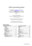
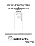
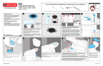
1
Foundry AR-Series AR1202 and
AR1204 Installation Guide
2100 Gold Street
P.O. Box 649100
San Jose, CA 95164-9100
Tel 408.586.1700
Fax 408.586.1900
June 2004
Copyright © 2004 Foundry Networks, Inc. All rights reserved.
No part of this work may be reproduced in any form or by any means – graphic, electronic or mechanical, including
photocopying, recording, taping or storage in an information retrieval system – without prior written permission of the
copyright owner.
The trademarks, logos and service marks (“Marks”) displayed herein are the property of Foundry or other third parties.
You are not permitted to use these Marks without the prior written consent of Foundry or such appropriate third party.
Foundry Networks, BigIron, FastIron, IronView, JetCore, NetIron, ServerIron, TurboIron, IronWare, EdgeIron,
IronPoint, AccessIron, the Iron family of marks and the Foundry Logo are trademarks or registered trademarks of
Foundry Networks, Inc. in the United States and other countries.
F-Secure is a trademark of F-Secure Corporation. All other trademarks mentioned in this document are the property of
their respective owners.
Contents
CHAPTER 1
GETTING STARTED...................................................................................... 1-1
INTRODUCTION ...........................................................................................................................................1-1
AUDIENCE ..................................................................................................................................................1-1
NOMENCLATURE .........................................................................................................................................1-1
RELATED PUBLICATIONS .............................................................................................................................1-2
LIST OF FEATURES .....................................................................................................................................1-2
HOW TO GET HELP .....................................................................................................................................1-5
WEB ACCESS .......................................................................................................................................1-5
EMAIL ACCESS .....................................................................................................................................1-5
TELEPHONE ACCESS ............................................................................................................................1-5
WARRANTY COVERAGE ...............................................................................................................................1-5
CHAPTER 2
PRODUCT INTRODUCTION ............................................................................ 2-1
OVERVIEW .................................................................................................................................................2-1
AR1202 .....................................................................................................................................................2-1
AR1202 FRONT PANEL .......................................................................................................................2-1
AR1202 BACK PANEL .........................................................................................................................2-1
LEDS ..................................................................................................................................................2-2
AR1204 ....................................................................................................................................................2-3
AR1204 FRONT PANEL ........................................................................................................................2-3
AR1204 BACK PANEL ..........................................................................................................................2-3
LEDS ..................................................................................................................................................2-4
CHAPTER 3
INSTALLATION ............................................................................................. 3-1
SITE PREPARATION ....................................................................................................................................3-1
ENVIRONMENT .....................................................................................................................................3-1
June 2004
© 2004 Foundry Networks, Inc.
iii
Foundry AR-Series AR1202 and AR1204 Installation Guide
POWER REQUIREMENTS .......................................................................................................................3-2
NETWORK CONNECTION .......................................................................................................................3-2
CABLES REQUIRED ...............................................................................................................................3-2
TOOLS REQUIRED ................................................................................................................................3-2
UNPACKING AND INSPECTING ................................................................................................................3-3
WALL-MOUNTING OPTION .....................................................................................................................3-4
RACK-MOUNTING OPTION .....................................................................................................................3-4
INSTALLING THE AR1202 AND AR1204 ROUTER ........................................................................................3-5
TABLE TOP INSTALLATION .....................................................................................................................3-5
NETWORK CONNECTIONS ....................................................................................................................3-8
CONNECTING THE WAN CABLE ...........................................................................................................3-8
CONNECTING DROP AND INSERT CABLES ..............................................................................................3-9
OPERATOR INTERFACE ........................................................................................................................3-9
CHAPTER 4
CONFIGURATION ......................................................................................... 4-1
LOGGING IN ...............................................................................................................................................4-1
COMMAND TIPS ....................................................................................................................................4-1
ETHERNET CONFIGURATION TIP ............................................................................................................4-2
CHANGING LOGIN PARAMETERS ...........................................................................................................4-2
DEFAULT CONFIGURATION ....................................................................................................................4-4
CONFIGURING DROP AND INSERT MULTIPLEXING ........................................................................................4-6
CONFIGURE THE DROP_INSERT INTERFACE ...........................................................................................4-6
CONFIGURE THE MODE TYPE ................................................................................................................4-6
DISPLAY INTERFACE DROP_INSERT FOUNDRY ........................................................................................4-7
CONFIGURE THE LINK ...........................................................................................................................4-7
DISPLAY INTERFACE DROP_INSERTS .....................................................................................................4-7
DISPLAY INTERFACE DROP_INSERT FOUNDRY ........................................................................................4-8
SWITCHING ROUTING/IPMUX MODES .......................................................................................................4-8
SWITCHING TO ROUTING MODE ............................................................................................................4-8
SWITCHING TO IPMUX MODE ................................................................................................................4-8
BOOT PROCESS ........................................................................................................................................4-8
UPGRADING SYSTEM SOFTWARE ................................................................................................................4-8
BEFORE DOWNLOADING THE AR01_#### FILE ..........................................................................................4-9
UPGRADING SOFTWARE .......................................................................................................................4-9
BOOTING FROM A NETWORK TFTP SERVER ......................................................................................4-10
APPENDIX A
SPECIFICATIONS .........................................................................................A-1
SYSTEM SPECIFICATIONS .......................................................................................................................... A-1
WAN INTERFACES .................................................................................................................................... A-3
LAN INTERFACES ..................................................................................................................................... A-4
CABLE PINOUTS ....................................................................................................................................... A-5
MIBS .................................................................................................................................................. A-7
iv
© 2004 Foundry Networks, Inc.
June 2004
Contents
APPENDIX B
TROUBLESHOOTING ....................................................................................B-1
ALARMS AND SYSTEM STATUS .................................................................................................................. B-1
WAN STATISTICS ..................................................................................................................................... B-1
NETWORK TESTS ...................................................................................................................................... B-2
PING TEST .......................................................................................................................................... B-2
OTHER TESTS ..................................................................................................................................... B-2
DIAGNOSTICS TIPS .............................................................................................................................. B-3
June 2004
© 2004 Foundry Networks, Inc.
v
Foundry AR-Series AR1202 and AR1204 Installation Guide
vi
© 2004 Foundry Networks, Inc.
June 2004
Chapter 1
Getting Started
Introduction
This guide describes how to install and configure the AR1202, AR1202E, AR1204, and AR1204E router.
Audience
This manual is designed for system administrators with a working knowledge of Layer 2 and Layer 3 switching and
routing.
If you are using a Foundry Layer 3 Switch, you should be familiar with the following protocols if applicable to your
network – IP, RIP, OSPF, BGP4, PIM, and VRRP.
Nomenclature
This guide uses the following typographical conventions to show information:
Italic
highlights the title of another publication and occasionally emphasizes a word or phrase.
Bold
highlights a CLI command.
Bold Italic
highlights a term that is being defined.
Underline
highlights a link on the Web management interface.
Capitals
highlights field names and buttons that appear in the Web management interface.
NOTE: A note emphasizes an important fact or calls your attention to a dependency.
WARNING: A warning calls your attention to a possible hazard that can cause injury or death.
CAUTION:
June 2004
A caution calls your attention to a possible hazard that can damage equipment.
© 2004 Foundry Networks, Inc.
1-1
Foundry AR-Series AR1202 and AR1204 Installation Guide
Related Publications
The following Foundry Networks documents supplement the information in this guide.
•
Release Notes
Printed release notes provide the latest information. If release notes are provided with your product, follow the
instructions contained within them instead of those provided in other documentation.
•
Foundry AR-Series AR1202 and AR1204 Quick Installation Guide
This guide is designed to assist users with the initial installation and deployment of the Foundry AR1202 twoport and AR1204 four-port router. The guide provides a brief overview of the installation and initial
configuration processes for the AR1202 and AR1204.
•
Foundry AR-Series Router Command Reference Guide
This detailed guide provides a complete description of all Foundry command line interface (CLI) commands
for T1 and E1 circuits.
•
Foundry AR-Series Router User Guide
This guide provides descriptions of commands available for Foundry ’ implementation of BGP, OSPF, and RIP
routing protocols.
•
Foundry AR-Series Router Configurations Guide
This guide provides example configurations.
To order additional copies of these manuals, do one of the following:
•
Call 1.877.TURBOCALL (887.2622) in the United States or 1.408.586.1881 outside the United States.
•
Send email to [email protected].
List of Features
Table 1.1 shows the features supported on AccessIron devices.
Table 1.1: Feature Supported in AccessIron Devices
Category
Feature
AR1202
AR1204
AR1208
AR1216
AR3201-T-CL
AR3202-T-CL
AR3201-CH
AR3202-CH
10/100 Fast Ethernet
2
2
2
T1/E1
Yes
-
-
Channelized T3
-
-
Yes
Clear Channel T3
-
Yes
-
Interfaces
WAN/LAN
WAN Protocols
PPP, PAP, Multilink PPP, Frame Relay, Multilink Frame Relay, (FRF.15, FRF.16.1) BCP, HDLC
Layer 2 Features
802.1Q VLAN tagging and forwarding over WLAN
Virtual LAN Domain (VLD) VLAN Double Tagging
1-2
© 2004 Foundry Networks, Inc.
June 2004
Getting Started
Table 1.1: Feature Supported in AccessIron Devices (Continued)
Category
Feature
AR1202
AR1204
AR1208
AR1216
AR3201-T-CL
AR3202-T-CL
AR3201-CH
AR3202-CH
Transparent Bridging
Jumbo Frames (4072 bytes)
IP Multiplexing
NAT mode
Transparent Layer 3 packet forwarding
Layer 3 Features
Routing
RIPv1/v2
OSPF
BGP4
Static Routing
ECMP (IP load balancing)
Multicast (PIM-SM, PIM-SSM, IGMP v2/v3)
High Availability
VRRP
BGP4 Multi-homing
Bundle Tracking
MLPPP Bundle Thresholding
LAN Interface Load Sharing with Failover
Security/
Management
June 2004
Stateful Packet Inspection Firewall with:
Layer-3 mode (router and NAT)
Policy-based NAT/PAT
Policy-based filters
URL and application content filtering
Time and rate limiting
Denial of Service protection
Network attack detection
Application Level Gateway support
Packet-level logging and syslog support
© 2004 Foundry Networks, Inc.
1-3
Foundry AR-Series AR1202 and AR1204 Installation Guide
Table 1.1: Feature Supported in AccessIron Devices (Continued)
Category
Feature
AR1202
AR1204
AR1208
AR1216
AR3201-T-CL
AR3202-T-CL
AR3201-CH
AR3202-CH
VPN
optional
on the
AR1202
and
AR1204
-
-
ACLs
DHCP
TFTP
PAP
RADIUS
TACACS+
SSH v2
GRE Tunneling
IPSec VPN with integrated IKE
Site-to-site VPN
Site-to-remote VPN
MD5 & SHA-1 authentication
Hardware accelerated encryption
3DES (168 bit), DES (56 bit), AES
(256 bit) encryption
QoS/Traffic
Management
RED
DiffServ
Class-based Queuing per:
IP address
Flow
VLAN tag
Application port
Frame Relay traffic shaping and policing
VLAN-802.1P 8 queue prioritization of VLAN frames
Service
Provisioning
Management (in-band, serial, Telnet, or modem) by:
CLI
SNMP
Monitoring
syslog
Statistics
Alarms
Diagnostics
BERT
Loopback testing
Traceroute
Reverse Telnet
Specialized
Features
1-4
Hospitality Web Redirection
© 2004 Foundry Networks, Inc.
June 2004
Getting Started
Table 1.1: Feature Supported in AccessIron Devices (Continued)
Category
Feature
AR1202
AR1204
AR1208
AR1216
AR3201-T-CL
AR3202-T-CL
AR3201-CH
AR3202-CH
Timed Access List
How to Get Help
Foundry Networks technical support will ensure that the fast and easy access that you have come to expect from
your Foundry Networks products will be maintained.
Web Access
•
http://www.foundrynetworks.com
Email Access
Technical requests can also be sent to the following email address:
•
[email protected]
Telephone Access
•
1.877.TURBOCALL (887.2622) United States
•
1.408.586.1881
Outside the United States
Warranty Coverage
Contact Foundry Networks using any of the methods listed above for information about the standard and extended
warranties.
June 2004
© 2004 Foundry Networks, Inc.
1-5
Foundry AR-Series AR1202 and AR1204 Installation Guide
1-6
© 2004 Foundry Networks, Inc.
June 2004
Chapter 2
Product Introduction
This chapter provides information about the Foundry AR1202 and AR1204 router front and back panels, LEDs,
cable connection ports, and panel components.
Overview
This section describes front- and back-panel components of the Foundry AR1202 and AR1204 router. Additional
information is also provided in following sections about external cables, wiring, and connection points.
The Foundry AR1202 and AR1204 is designed to provide WAN to LAN networking connectivity for branch office
communication and primary Internet access for medium-size businesses. The AR1202 and AR1204 is a T1/E1
router providing two WAN ports, two 10/100 Fast Ethernet ports, an AUX port, and a local/remote management
Console port. The base system ships with one active WAN port (WAN 1) and one active Ethernet port (FE 0).
Software licence keys may be purchased to activate one additional WAN and/or one Ethernet port. Contact
Foundry sales for more information.
AR1202
AR1202 Front Panel
The router front panel houses the system LEDs.
Figure 2.1
AR1202 Router Front Panel
LINK/ACT HS
WAN Port
LEDs 1-2
DUP
Ethernet 0 LEDs
LINK/ACT HS
DUP
Power LED
Ethernet 1 LEDs
AR1202 Back Panel
The AR1202 router back panel provides connections for two WAN ports, two 10/100 Base-T Ethernet ports, one
AUX port, one Console port, and a 12 VDC power input jack.
June 2004
© 2004 Foundry Networks, Inc.
2-1
Foundry AR-Series AR1202 and AR1204 Installation Guide
Figure 2.2
AR1202 Router Back Panel
WAN Ports 1 - 2
Fast Ethernet
Port 0
Fast Ethernet
Port 1
AUX Port
Console
Port
12 VDC
Input Jack
LEDs
The AR1202 front-panel LEDs indicate real-time unit status. Table 2.1provides information about how to interpret
the LED states.
Table 2.1: LED Descriptions
Port
Description
Color
WAN STATUS 1/
2
Indicates traffic activity
on this interface
Green = normal activity
Red = alarm state
Yellow = test mode
LINK/ACT
Indicates traffic activity
on this interface
Green = link is operational
Blinking Yellow = either receiving or sending
traffic
Red = packet collisions
HS
Indicates traffic speed
on the interface
Off = 10 Mbps
Green = 100 Mbps
DUP
Indicates the type of
duplex mode
Off = Half duplex
Green = Full duplex
Foundry Logo
Back lighted when
power is on
Blue
Power
Indicates system
power status
Green = power on
Off = power off
ETHERNET 0 / 1
2-2
© 2004 Foundry Networks, Inc.
June 2004
Product Introduction
Table 2.2: AR1202 Back-Panel Ports
Connector
Description
WAN 1 - WAN 2
WAN connection ports. These ports accept cables with RJ-48C connectors.
FE 0 / 1
Ethernet LAN connection ports. These ports accept cables with RJ-45 cable
connectors.
AUX
Reverse telnet connection. This port accepts a cable with a male DB-9
connector.
Console
Console management port. This port accepts a cable with an RJ-45 cable
connector.
DC power
12 VDC power connection. This port accepts the 2 mm. power connector on
the DC power supply cable that ships with the AR1202 router.
AR1204
AR1204 Front Panel
The router front panel houses the system LEDs.
The following section identifies and describes the AR1204 router network ports and LEDs.
Figure 2.3
AR1204 Router Front Panel
LINK/ACT HS
WAN Port
LEDs 1-4
DUP
Ethernet 0 LEDs
LINK/ACT HS
DUP
Power LED
Ethernet 1 LEDs
AR1204 Back Panel
The AR1204 router back panel provides connections for four WAN ports, two 10/100 Base-T Ethernet ports, one
AUX port, one Console port, and a 12 VDC power input jack.
June 2004
© 2004 Foundry Networks, Inc.
2-3
Foundry AR-Series AR1202 and AR1204 Installation Guide
Figure 2.4
AR1204 Router Back Panel
WAN Ports 1 - 4
Fast Ethernet
Port 0
Fast Ethernet
Port 1
AUX Port
Console
Port
12 VDC
Input Jack
LEDs
The AR1204 front-panel LEDs indicate real-time unit status. Table 2.3provides information about how to interpret
the LED states.
Table 2.3: LED Descriptions
Port
Description
Color
WAN STATUS
1-4
Indicates traffic activity on
this interface
Green = normal activity
Red = alarm state
Yellow = test mode
LINK/ACT
Indicates traffic activity on
this interface
Green = link is operational
Blinking Yellow = either receiving or sending
traffic
Red = packet collisions
HS
Indicates traffic speed on
the interface
Off = 10 Mbps
Green = 100 Mbps
DUP
Indicates the type of
duplex mode
Off = Half duplex
Green = Full duplex
Foundry Logo
Back lighted when power
is on
Blue
Power
Indicates system power
status
Green = power on
Off = power off
ETHERNET 0/1
2-4
© 2004 Foundry Networks, Inc.
June 2004
Product Introduction
Table 2.4: AR1204 Back-Panel Ports
June 2004
Connector
Description
WAN 1 - WAN 4
WAN connection port. These ports accept cables with RJ-48C connectors. If
drop and insert is configured, then ports 1 and 2 are reserved for that
feature.
FE 0 - FE 1
Ethernet LAN connection ports. These ports accept cables with RJ-45 cable
connectors.
AUX
Reverse telnet connection. This port accepts a cable with a male DB-9
connector.
Console
Console management port. This port accepts a cable with an RJ-45 cable
connector.
DC power
12 VDC power connection. This port accepts the 2 mm. power connector on
the DC power supply cable that ships with the AR1204 router.
© 2004 Foundry Networks, Inc.
2-5
Foundry AR-Series AR1202 and AR1204 Installation Guide
2-6
© 2004 Foundry Networks, Inc.
June 2004
Chapter 3
Installation
This chapter describes how to install and prepare the Foundry AR1202 and AR1204 router for operation.
Information is also provided describing the system front and back panels, operator interface, how to mount the
chassis, and how to connect network and power cables.
Before you install the AR1202 and AR1204, familiarize yourself with the network interface and power connections
described in this chapter.
Site Preparation
Before installing a Foundry AR1202 and AR1204 router, ensure that the site conditions comply with the following
requirements and that the mounting equipment, tools, and cables are available at the installation site.
Environment
Site location is important for the proper operation of the AR1202 and AR1204 router. Place the unit in a clean, dry
environment with adequate air circulation. Allow additional clearance around the system for foot traffic and access
to cable connectors on the rear panel.
Figure 3.1 shows the convection cooling vents on top of the unit. To prevent an over-temperature condition, which
could result in system failure or performance degradation, make sure that these vents are not obstructed.
NOTE: In normal operation, the router will be warm to the touch.
Figure 3.1
Chassis Air Flow
CAUTION: Do not stack routers on top of each other. Doing so will defeat the convection cooling ability of the
router and such action could lead to equipment damage.
Refer to “Specifications” on page A-1 for more information about environmental requirements.
June 2004
© 2004 Foundry Networks, Inc.
3-1
Foundry AR-Series AR1202 and AR1204 Installation Guide
Power Requirements
The AR1202 and AR1204 router operates on 12 VDC power. A 12 VDC power supply and an AC power cord are
shipped with the router.
Network Connection
To successfully complete the installation, the router must be connected to a network. Before you start the
installation, make sure that a live network connection is available at the installation site.
Cables Required
The AR1202 and AR1204 router ships with a Console cable. You will need to obtain additional cables for your
specific application. The following additional cables are required to install the AR1202 and AR1204 router.
•
One or two RJ-45, male/male, category 5, 26 AWG (minimum), twisted-pair, straight-through cable (Ethernet
LAN connection)
See Table A.8 on page A-6 for cable pinout information.
Refer to Figure 3.2 on page 3-2 to identify this cable.
Figure 3.2
•
Ethernet Cable
One or two RJ-48C, male/male, category 5, 26 AWG (minimum), twisted-pair, straight-through WAN cable
See Table A.9 on page A-6 for cable pinout information.
Refer to Figure 3.3 to identify this cable.
Figure 3.3
WAN Cable
Tools Required
The following tools are required to install the Foundry AR1202 and AR1204 router.
Figure 3.4
Required Tools
#2 Phillips screwdriver
3-2
#3 Phillips screwdriver
1/4 inch flat blade screwdriver
© 2004 Foundry Networks, Inc.
June 2004
Installation
Unpacking and Inspecting
After opening the shipping carton, remove and save all packing materials and boxes.
NOTE: Save the packing materials. If you need to return the product, you will need to repack the unit with the
original packing material.
Check the packing slip and contents of the shipping carton to ensure that you have received the following items.
Figure 3.5
Items Shipped with the AR1202 and AR 1204 Router
Foundry router (AR1204 shown)
Quick Start Guide, CD ROM, product registration
card, and product warranty
Power supply
RJ-45 Console cable
AC power cord
Female Console cable to PC adapter
Power supply cord retainer bracket
Male DB-25 modem adapter
Inspect the AR1202 and AR1204 and the shipping carton for damage that may have occurred during shipping. If
you discover damage or that items are missing, contact Foundry Technical Support. Refer to the Foundry website
for contact information.
June 2004
© 2004 Foundry Networks, Inc.
3-3
Foundry AR-Series AR1202 and AR1204 Installation Guide
Wall-Mounting Option
An optional wall-mounting assembly is available for mounting the AR1202 and AR1204 router on a vertical surface. The
wall-mount components are shipped in the same box with the AR1202 and AR1204 router, and are shown in the following
figure:
Figure 3.6
Wall-Mount Components
Wall-mount bracket
Power supply strap
Router to wall-mount bracket screws: (4) 4-40 x
.250 inch Phillips pan head
Hollow wall anchors
Wall-mount screws: (4) 6 x 1 inch Phillips pan head
Rack-Mounting Option
An optional rack-mounting tray is available for installing the AR1202 and AR1204 router in an equipment rack. The
following items are shipped in a separate carton:
3-4
© 2004 Foundry Networks, Inc.
June 2004
Installation
Figure 3.7
Rack-Mount Components
(2) Rack Carriage Assemblies
Rack Tray
2) Mounting Brackets
(4) Velcro Tie Wraps
4) 10-24 x .5 Phillips
Pan Head Screws for
Equipment Rack
(4) 10-24 x .5 Phillips
Pan Head Screws for
Equipment Rack
(2 sets) Velcro Mounting Pads
(6) 6-32 x .25 Phillips
Flat Head Mounting
Bracket Screws
4) 4-40 x .25 Phillips
Pan Head Rack Carriage
Screws
Installing the AR1202 and AR1204 Router
The AR1202 and AR1204 router can be installed on a table top, in a Telco equipment rack (using the optional
rack-mounting tray), or on a vertical surface (using the optional wall-mounting assembly). The router ships with a
Console cable. You will need to obtain additional cables for your specific application. Refer to Figure 3.2 on
page 3-2 and Figure 3.3 on page 3-2.
CAUTION:
Do not block the cooling vents on the top of the unit.
NOTE: For problem-free operation, the router should be located in an area with adequate ventilation.
Table Top Installation
To install the AR1202 and AR1204 for operation on a table top, follow this procedure. Refer to Figure 3.8 on
page 3-6.
June 2004
© 2004 Foundry Networks, Inc.
3-5
Foundry AR-Series AR1202 and AR1204 Installation Guide
Figure 3.8
Table Top Installation
110/120 VAC Outlet
Threaded Hole
12 VDC Port
Cable Retainer
1.
Place the unit on the table surface.
2.
Insert the DC power cable into the DC input jack on the front of the unit.
3.
Attach the cable retainer bracket behind the molded strain relief on the power supply cable near the DC input
jack.
4.
Engage and secure the captive screw on the retainer in the threaded hole adjacent to the input jack on the
router.
5.
Connect the appropriate ends of the AC power cord to the power supply and a 110/120 VAC outlet.
NOTE: Ensure that the cables are router out of the way of foot traffic.
Wall-Mount Installation
Follow this procedure to attach the Foundry AR1202 and AR1204 router to a vertical surface. Refer to Figure 3.9
on page 3-6.
Figure 3.9
1.
3-6
Wall Mounting the AR1202 and AR1204 Router
Attach the router to the wall mount assembly using four (provided) Phillips pan head 4-40 x .250 inch screws.
© 2004 Foundry Networks, Inc.
June 2004
Installation
Ensure that the router is oriented in a manner that allows the LEDs to be visible.
2.
Attach the assembly with the mounted router to the wall surface with four (provided) 6 x 1 inch Phillips pan
head screws and hollow wall plastic anchors.
NOTE: The provided hollow wall anchors are not designed for installation in hard walls. These anchors should
only be installed in a sheet rock (gypsum wall board) wall.
3.
Fit the AC strap over the power supply and then place the power supply on the wall mount bracket within the
four locating tabs.
4.
Engage and tighten the AC strap captive screw to secure the power supply to the wall mount assembly.
5.
Attach the cable retainer to the DC power cord behind the molded strain relief on the cable.
6.
Insert the DC power cable jack into the 12 VDC port on the back of the router.
7.
Engage and tighten the captive screw on the cable retainer in the threaded hole adjacent to the DC input jack
on the router.
8.
Connect the appropriate ends of the AC cord to the secured power supply and a 110/120 VAC outlet.
Rack-Mount Installation
To mount the AR1202 and AR1204 in an equipment rack, follow this procedure. Refer to Figure 3.10.
Figure 3.10
Rack Mounting the AR1202 and AR1204 Router
1.
Determine the mounting position for the rack tray in the equipment rack (front or mid mount) and attach the
mounting brackets using the four (provided) 6-32 x .250 inch flat head Phillips screws.
2.
Attach the router to the carriage assembly using four (provided) Phillips pan head 4-40 x .250 inch screws.
3.
Engage the carriage assembly in the rack tray rails and slide the assembly all the way in.
4.
Fit the AC strap over the power supply and then place the power supply on the rack tray between the raised
tab and the back edge of the tray.
5.
Engage and tighten the AC strap captive screw to secure the power supply to the rack tray.
6.
Attach the cable retainer bracket to the DC power cord behind the molded strain relief on the cable.
7.
Insert the power cable jack into the 12 VDC port on the back of the router.
June 2004
© 2004 Foundry Networks, Inc.
3-7
Foundry AR-Series AR1202 and AR1204 Installation Guide
8.
Engage and tighten the captive screw on the cable retainer bracket in the threaded hole adjacent to the DC
input jack on the router.
9.
Coil the excess cable and secure it on the tray behind the router.
10. Mount the tray in the equipment rack using either four (provided) Phillips pan head 10-24 x .5 inch screws or
four (provided) Phillips pan head 12-32 x .5 inch screws, whichever fits the equipment rack.
11. Connect the network cables to the router. Secure the cables in the clips located on the bottom of the carriage
assembly. Refer to “Network Connections” on page 3-8.
12. Connect the appropriate ends of the AC cord to the secured power supply and a 110/120 VAC outlet.
13. Using a small flat blade screwdriver, engage and tighten the captive screw to secure the carriage assembly to
the rack tray.
Network Connections
The following sections describe how to connect various network cables to the Foundry AR1202 and AR1204
router.
Connecting the Ethernet Cable
The front panel on the router accommodates one LAN connections. Use a category 5, twisted-pair Ethernet cable
with RJ-45 connectors to connect to the LAN. Refer to Figure 3.2 on page 3-2 to identify this cable.
Follow this procedure to connect the AR1202 and AR1204 to an Ethernet LAN network.
1.
Connect the RJ-45 connector of a category 5 rated Ethernet cable to either the Ethernet 0 port on the back
panel.
2.
Connect the RJ-45 connector on the other end of the cable to the LAN port.
Make sure that the cable connectors are locked and secure in the ports. See Table A.8 on page A-6 for pinout
information about this cable.
Figure 3.11
Connecting the Ethernet Cable
Ethernet LAN Port
Fast Ethernet Port 0
Fast Ethernet Port 1
Connecting the WAN Cable
The back panel accommodates up to two WAN (model specific) cables. Use 26 AWG (minimum) category 5,
twisted-pair cable with RJ-48C connectors for this interface. Refer to Figure 3.3 on page 3-2 to identify this cable.
CAUTION: To reduce the risk of fire, use only number 26 AWG or larger UL Listed or CSA Certified Telecommunication Line Cord for all network connections.
Follow this procedure to connect a WAN port to the network:
1.
3-8
Insert the RJ-48C connectors on one end of one cable in the appropriate port on the Service Provider’s
demarcation point.
© 2004 Foundry Networks, Inc.
June 2004
Installation
2.
Insert the RJ-48C connectors on the other ends of the cables in the WAN ports on the front panel of the
Foundry router.
Make sure that the cable connectors are locked and secure in the ports. See Table A.9 on page A-6 for pinout
information about this cable.
Figure 3.12
Connecting the WAN Cable
Connect to Service
Provider’s Demarcation
Point
WAN Port 1
Connecting Drop and Insert Cables
WAN ports 1 and 2 can alternatively be used for drop and insert traffic. Port 1 is designated for voice; port 2 is
used for data traffic. Use two 26 AWG (minimum) category 5, twisted-pair cables with RJ-48C connectors to
establish this connectivity.
Figure 3.13
Connecting Drop and Insert Cables
Connect to the Local PBX Port
Connect to Service Provider’s
Demarcation Point
RJ-48C WAN Cables
To connect drop and insert cables, follow this procedure. Refer to Figure 3.13 on page 3-9.
1.
Insert the RJ-48C connector of one end of one WAN cable in WAN port 1 on the router.
2.
Connect the other end of this cable to the local PBX port.
3.
Insert the connector on one end of the second cable to WAN port 2 on the router.
4.
Connect the other end of this cable to the Service Provider’s demarcation point.
5.
For information about configuring drop and insert, refer to the Command Reference Guide.
Operator Interface
Local Management
The AR1202 and AR1204 can be locally configured, operated, and managed using an operator console
connected to the Console port. A terminal (VT-100 or equivalent) or workstation with terminal emulation software
can be used for the operator console. Connect the console to the AR1202 and AR1204 router Console port using
an RJ-45 cable with switched ends. If your terminal equipment requires a special cable, see Table A.7 on page A5 for connector pinout information.
To connect the Console cable:
June 2004
© 2004 Foundry Networks, Inc.
3-9
Foundry AR-Series AR1202 and AR1204 Installation Guide
1.
Connect the RJ-45 Console cable to the Console port on the router.
2.
Connect the other end of the RJ-45 Console cable to the RJ-45 end of the adapter.
3.
Connect the DB-9 end on the adapter to the management terminal or workstation.
Figure 3.14
Connecting the Console Cable (Local Management)
RJ-45 to DB-9 Adapter
Console Port
Remote Management
A modem can be connected to the Console port and used to configure, operate, and manage the AR1202 and
AR1204 remotely.
Figure 3.15
Connecting a Modem for Remote Management
DB-25 Modem Adapter
Modem
Console Port
Follow this procedure to connect the AR1202 and AR1204 to a modem. Refer to Figure 3.15 on page 3-10.
1.
Connect the male end of the DB-25 adapter to the female DB-25 port on the modem.
2.
Connect one end of a supplied RJ-45 cable to the RJ-45 port in the DB-25 adapter.
3.
Connect the other end of the RJ-45 cable to the Console port on the AR1202 and AR1204.
4.
Refer to the Foundry Support website for modem configuration information.
If a workstation is used for the remote management console, use VT-100 terminal emulation software or
equivalent, and configure the software as specified for modems.
Console Messages
Alarm messages are displayed at the console when system logging is configured. Refer to the configure system
logging console command and related system logging commands in the Command Reference Guide for more
information about how to configure specific alarm events.
For more information about command usage for T1 and E1 products, refer to the Command Reference Guide.
This guide is available on the Foundry website.
3 - 10
© 2004 Foundry Networks, Inc.
June 2004
Chapter 4
Configuration
This chapter describes how to login; change the default password, configure the router and users, and change the
factory default configuration. The boot process and software upgrade process is also discussed in detail.
Logging In
If you have not established a local console connection, see “Operator Interface” on page 3-9 for more information.
The following figure shows the login sequence and the initial prompt after login is complete.
Figure 4.1
Initial CLI Prompt
login: username
password:
username logged in on Fri May 7 05:28:01 2004
from console
Foundry CLI
Initial CLI Prompt
foundry-model#
NOTE: The default host name is Foundry-model number, e.g., Foundry-AR1202#.
Command Tips
Use the following command tips and shortcuts with command line interface commands.
•
To display all commands, type tree.
•
To access help associated with a command, type help <command name>. You may also use the ? key after
any command.
•
To exit back one level in the command hierarchy, type exit and press Return.
•
To exit the command mode and/or return to the base CLI prompt, press the key combination Ctrl-Z.
•
Type the first two letters of a command, and then press the Tab key to automatically spell out the command.
•
Scroll through the available commands using the Tab key.
June 2004
© 2004 Foundry Networks, Inc.
4-1
Foundry AR-Series AR1202 and AR1204 Installation Guide
Ethernet Configuration Tip
To avoid Ethernet mismatch problems, the AR1202 and AR1204 router and the network device to which it is
attached should both be configured identically for speed and duplex. For example, if the router is configured for
auto-negotiation and the far end is configured manually, the router detects the speed, but defaults to half-duplex
mode. To ensure correct operation, either manually configure each device for speed and duplex settings, or
configure both devices to auto-negotiate.
Changing Login Parameters
The System Administrator login consists of two components: the user name and the password. The initial login
name is always foundry, but you can change this to suit your needs after logging in for the first time. The default
password for user Foundry, foundry, should be changed as soon as possible to ensure only authorized access to
the router.
For more information about command usage for T1 products, refer to the Command Reference Guide: Domestic
Products. For information about command usage for E1 products, refer to the Command Reference Guide:
International Products. These guides are available on the Foundry website.
Password
This procedure enables the system administrator to change any or all user passwords, or any user to change their
password on the AR1202 and AR1204. The password must be 3-10 characters.
To change the password:
1.
Access the password configuration mode.
example:
Foundry-AR1202# password
The system prompts for the current user name.
2.
Type foundry, and then press Return.
The system prompts for the old password.
3.
Type foundry, and then press Return.
The system prompts for the new password.
4.
Type your new password, and then press Return.
The system prompts you to verify the new password.
5.
Type the new password again and then press Return.
A message is appears confirming that the password has been changed.
Administrator Account
This procedure changes the administrator login name (Level 1 access) to a user-specified name. The default is
foundry.
To change the account name:
1.
Access the configure mode.
example:
Foundry-AR1204# configure term
2.
Change the account name.
example:
Foundry-AR1204/configure# admin_name Greg
This example above changes the Level 1 user name to Greg.
The system displays a confirming message: “Administrator account name changed to Greg.”
4-2
© 2004 Foundry Networks, Inc.
June 2004
Configuration
NOTE: Changing the administrator login name does not change the administrator’s password. Use the password
procedure to change the password.
System Host Name
Use the configure hostname command to assign a host name to the Foundry router. Once assigned, the host
name becomes the command line interface (CLI) prompt name.
To configure the host name:
1.
Access the terminal configuration mode: Foundry-AR1204# configure term
2.
Type hostname, and then type a new host name.
3.
Press Return.
example:
Foundry-AR1204/configure# hostname Fremont
In the above example, the new host name for the system is Fremont. The CLI prompt changes to Fremont,
accordingly.
example:
Fremont/configure#
Date and Time
Date and time is set using the configure date command. You must specify the offset direction, hours, and
minutes before entering the exact date and time. The number of hours and minutes is offset from (earlier than or
later than) a Universal Time Coordinated clock (UTC).
NOTE: Universal Time Coordinated (UTC), the internationally recognized measure of time, is also known as
Greenwich Mean Time (GMT).
To set the date and time:
1.
Enter the terminal configuration mode: Foundry-AR1204# configure term
2.
Press Return.
3.
Use the date command to enter the hours and minutes offset from UTC, followed by the current month, day,
year, hour (24-hour format), minute, and second.
To enter the date and time: May 10, 2004, 2:40:35 pm, see the following example:
example:
Foundry-AR1204/configure# date + 0 0 mo 5 d 10 y 2004 h 14 mi 40 s 35
NOTE: The hour, minute, and second entries are optional.
The router confirms the setting by automatically displaying the date and time. To confirm the date and time
parameters, use the display date command.
Adding Users
The configure user command allows the system administrator to add up to 15 users (login ID) and assign each
user an access privilege (levels 2-4). Only the system administrator (level 1) can add, modify, or remove this
information.
To add a new user:
1.
Enter the terminal configuration mode: Foundry-AR1204# configure term
2.
Type user name, enter the name that you want to add, and then enter the access level to be assigned to that
name (optional). The user name may be up to 30 characters. The password must be 3-10 characters.
June 2004
© 2004 Foundry Networks, Inc.
4-3
Foundry AR-Series AR1202 and AR1204 Installation Guide
example:
Foundry-AR1204/configure# user John level 2
The system prompts you to enter a new password.
3.
Enter the new password.
The system prompts you to re-enter the new password.
4.
Re-enter the new password.
The system confirms that the password is set and confirms the name of the added user.
You can use the display user_accounts command to view user information.
Removing Users
The no user name command allows the system administrator to remove configured user names from the Foundry
system.
To remove a user name:
1.
Type no user name, followed by the user’s name.
example:
Foundry-AR1204/configure# no user John
2.
Press Return.
The user name is removed from the system.
Default Configuration
For more information about command usage, refer to the appropriate Foundry Command Reference Guide (either
the domestic or international version).
There are three ways to restore factory default configuration settings. Remember to reboot the router after
performing any of the following procedures.
•
Clear the contents of the system.cfg file
clear cfg_file system.cfg
•
Delete the system.cfg file
rm system.cfg
•
Rename and remove the system.cfg file
copy system.cfg system.bk
rm system.cfg
After performing any of the above options, the system.cfg file no longer exists. Subsequently, a “file not found”
error message is displayed upon rebooting the system. This message will not impact operation, and it should be
ignored.
NOTE: If you change any of the factory default settings, issue the save local command to retain the changed
configuration before rebooting.
The following tables show the factory default configuration for the Foundry AR1202 and AR1204 router.
4-4
© 2004 Foundry Networks, Inc.
June 2004
Configuration
Table 4.1: Default Configuration Values
Parameter
Default
speed
auto (negotiates 10 Mbps or 100 Mbps)
address
uses the current address stored in the system.cfg file (if one exists),
otherwise an IP address must be configured from the command line
interface
duplex
auto (negotiates half-duplex or full-duplex)
Table 4.2: Default IP Routing Settings
Parameter
Default
IP routing 1
disabled
IP multiplexing
enabled
2
1, 2 IP routing and IP multiplexing are mutually exclusive of each other. Only one
can be enabled at a time.
Table 4.3: Default Telecommunications Values
June 2004
Parameter
Default Value
Optional Values
framing
esf
d4
linecode
b8zs
ami
clock_source
internal
line
linemode
csu
dsx
lbo
0 dB
7.5 db
15 db
22.5 db
cable length
1 (0 - 110 ft.)
2 (110 - 220 ft.)
3 (220 - 330 ft.)
4 (330 - 440 ft.)
5 (440 - 550 ft.)
6 (550 - 660 ft.)
fdl
ANSI and ATT unit protocol
enabled
ANSI (only)
ATT (only)
yellow_alarm
disabled
generate
detect
generate and detect
© 2004 Foundry Networks, Inc.
4-5
Foundry AR-Series AR1202 and AR1204 Installation Guide
Table 4.4: E1 Interface Default Configuration
Parameter
Default Value
Optional Values
framing
crc
non-crc
disabled
linecode
HDB3
no optional value
clock_source
internal
line
linemode
short_haul
long_haul
jitter
enabled
disabled
lbo
43 db
12 db
yellow_alarm
generate and detect
no optional value
Table 4.5: Terminal Emulation Defaults
Setting
9600 bps
8 data bits
1 stop bit
no parity
XON/XOFF flow control
Configuring Drop and Insert Multiplexing
To use this feature, WAN ports 1 and 2 must be active and licensed for use. Drop and insert supports one-to-one
mapping of 1 to 24 voice-carrying DS0s on the PBX interface to the equivalent DS0s on the network port. The
PBX is connected to WAN port 1 and the DS0s are mapped to the carrier facility on WAN port 2.
In this example, DS0 channels 1-10 and 18-24 from WAN links 1 and 2 are configured for drop and insert traffic.
The remaining DS0 channels (11-17) are available for IP traffic.
Configure the drop_insert interface
The interface name can be a maximum of 8 characters.
host/configures interface drop_insert Foundry
Configure the mode type
The mode type can be one of the following three values:
4-6
0
data only (default)
1
data and voice
2
voice only
© 2004 Foundry Networks, Inc.
June 2004
Configuration
host/configures interface drop_insert Foundry mode 2 1
Note that “2” represents port 2. This is the only value that will be accepted. The “1” represents the mode (data and
voice) for which port 2 is configured.
Display interface drop_insert Foundry
host# show interface drop_insert Foundry
drop_insert Foundry
-----------------------
number of links
0
Configure the link
The default value for timeslots is all (available). Signaling can be configured for:
1
RBS (default)
2
ISDN
host/configures interface/drop_insert Foundry# t1 1 2 timeslots 1-10,10-24 signaling 1
Display interface drop_inserts
host# show interface drop_inserts
drop_insert table
-----------------Foundry
Link Usage Summary:
June 2004
© 2004 Foundry Networks, Inc.
4-7
Foundry AR-Series AR1202 and AR1204 Installation Guide
Display interface drop_insert Foundry
host# show interface drop_insert Foundry
drop_insert Foundry
-----------------------
number of links
2
Interface Mode: DATA AND VOICE MODE
Signaling Type: RBS
Switching Routing/IPMUX Modes
To switch between IPMux and dynamic routing modes, a valid software license must be installed on the AR1202
and AR1204 router. Contact Foundry and provide the serial number for the router.
Switching to Routing Mode
To switch from IPMux to dynamic routing mode, issue the following command:
Foundry-AR1204/configure# system routing
A message is displayed warning you to issue the save local command before the router reboots and you must
confirm that you want to change to routing mode. Enter Y and press the Return key. The AR1202 and AR1204
reboots into dynamic routing mode.
Switching to IPMux Mode
To switch from dynamic routing to IPMux mode, issue the following command:
Foundry-AR1204/configure# no system routing
A message is displayed warning you to issue the save local command before the router reboots and you must
confirm that you want to change to IPMux mode. Enter Y and press the Return key. The AR1202 and AR1204
reboots into IPMux mode.
Boot Process
When power is applied to the Foundry system, the Flash is checked for a downloadable boot image. If a boot
image file is found in the Flash, the file is executed. Otherwise, the boot image is executed from the factory image
stored in the boot ROM. Next, the Foundry operating system is loaded from the AR01_#### file residing in the
Flash. Power-up diagnostics such as flash test, memory test, etc. are run and then the Ethernet and WAN
interfaces are installed. The router is then configured using settings previously saved in the system.cfg file. Once
these settings are configured, the router is ready for operation and user login.
Upgrading System Software
The Foundry command line interface (CLI) provides commands that allow you to upgrade the AR1202 and
AR1204 router with new software. Every system is furnished with a software image file (AR01_####) and a boot
image file (T1000.bin). Using the TFTP protocol, the latest versions of these files can be loaded onto a Foundry
router from any accessible TFTP server.
4-8
© 2004 Foundry Networks, Inc.
June 2004
Configuration
A software upgrade consists of two files: AR01_#### and T1000.bin. The .Z file is the operating system for the
Foundry system; the .bin file contains the downloadable boot images.
NOTE: Foundry systems do not support two simultaneous downloads.
NOTE: Refer to the appropriate Command Reference Guide (domestic or international products) for specific
command parameters, options, and context.
Before Downloading the AR01_#### File
If you must issue the file download command, do so only when the source of the download file is currently
answering a ping command and there is no immediate concern about unscheduled power outages. This situation
is a cause for concern because a problem can arise when there is insufficient Flash space to hold a backup copy
of the downloaded AR01_#### file. When this occurs, the system prompts for approval to continue. However, if
power fails or there are network problems during the file download, the system may not be able to boot from flash
because the file may be incomplete or corrupt. If this occurs, you can boot using FTP. Refer to “Booting From a
Network TFTP Server” on page 4-10 for this procedure.
Upgrading Software
To upgrade the AR01_#### and T1000.bin files:
1.
Download AR01_#### and T1000.bin from the Foundry Support page on the website and place it on a server
that is running a TFTP daemon.
2.
Ensure that network connectivity exists between the Foundry system being upgraded and the TFTP server
holding the new file. Pinging the server from the Foundry system is a good method to use to prove
connectivity.
3.
Download files to the Flash. The general format for the download commands is:
file download
server_ip
source_file
local_file
server_ipThe IP address of the server holding the upgrade files.
source_filePath and file name of the file to be downloaded.
local_fileFile name to be used in local flash memory.
For example, a typical sequence might consist of:
•
4.
downloading all files to the main board:
file/download
10.10.1.1
r7/AR01_####
AR01_####
file/download
10.10.1.1
r7/T1000.bin
T1000.bin
Move the .bin images to the downloadable boot area:
file/copy_boot T1000.bin
file/validate_boot T1000.bin (This should validate the copy_boot procedure.)
5.
Make sure you are booting the images from the Flash and then reboot the system:
configure# boot AR01_####
Then type “Y” to reboot the router.
6.
After reboot, log in and verify the proper software version with the following command:
display version
June 2004
© 2004 Foundry Networks, Inc.
4-9
Foundry AR-Series AR1202 and AR1204 Installation Guide
Booting From a Network TFTP Server
In the rare and unlikely situation where a software version upgrade fails, a network boot may be performed as
described in the following procedure.
1.
Assume that the new AR01_#### download failed when the following command was issued:
Router# file download 192.168.10.1 tftpdir/8.0/AR01_####
This command line is appropriate when the new upgrade AR01_#### file resides on a tftp server host with IP
address 192.168.10.1, in a directory named tftpdir/8.0.
Upon a download failure (and corruption or deletion of the AR01_#### file in Flash), the AR1202 and AR1204
router may not be able to boot.
2.
Make note of which Ethernet interface (0 or 1) connects the system to the tftp server host.
3.
Connect a terminal or terminal emulator to the console port of the Foundry system using the cable supplied.
Configure the terminal for 9600 bps, 8 data bits, 1 stop bit, no parity, and XON/XOFF flow control.
4.
Power cycle the AR1202 and AR1204.
5.
Press and hold the Enter (Return) key while the system boots (usually 10-15 seconds).
6.
The following (or similar) text is output to the terminal:
Copyright (c)
Copyright (c)
CPU: Foundry
Variation: 8.3.2
RSP Version 1.1/2
Creation date Sep 8, 2000, 19:14:24
Press any key to stop auto-boot....
1
[Foundry Boot. reboot in 1 minute if CR not pressed]:
[Foundry Boot]:
[Foundry Boot]:
.
.
.
[Foundry Boot]:
7.
Type c, and press the Enter key.
NOTE: At any point in this procedure, online help can be accessed by typing ? and pressing the Enter key.
8.
If Ethernet 0 is connected to the tftp server host, change fl0 (flash boot) to InPci0.
The following text is output to the terminal:
[Foundry Boot]: c
‘_’= clear field; ‘=’ = go to previous field; ^D = quit
boot device
processor number
9.
4 - 10
: f10 InPci0
) 0
Press the Enter key.
© 2004 Foundry Networks, Inc.
June 2004
Configuration
The following text is output to the terminal:
host name
: host
10. To keep this parameter, press the Enter key.
The following text is output to the terminal:
file name
: /flash1/T2000.Z
11. Enter the path-qualified file name: type /tftpdir/r4.6/AR01_#### (or whatever is consistent with the file
download command in the above example) and press the Enter key.
The following text is output to the terminal:
1net on ethernet [e] : 10.1.0.1:fff0000
12. Input the address for the Foundry system to use as an tftp client to the tftp host. Type 111.2.3.3:ffffff00 (or
whatever is appropriate for your network configuration) and press the Enter key.
Note that the netmask is specified in hexadecimal after a colon (here a 24-bit netmask). You must be in the
same subnet as the tftp host or the same subnet as the default router through which you will access the tftp
host.
The following text is output to the terminal:
1net on backplane [b] :
13. Press the Enter key. The following text is output to the terminal:
host 1net [h]
: 10.11.12.13
14. At this point, the tftp host address must be entered. Type 192.168.10.1 (or whatever is consistent with the
downloadNCM command in the above example) and press the Enter key.
The following text is output to the terminal:
gateway 1net [g]
: 10.11.12.13
15. If a gateway does not exist between the Foundry router and the tftp server, then this can be left blank.
However, it is required if the router and the tftp server reside in different subnets. For this example you would
enter 111.2.3.254.
The following text is output to the terminal:
user [u]
: wind
16. Make sure to type wind. Then set the password also to wind. Press the Enter key.
The following text is output to the terminal:
ftp password [pw] [blank = use rsh] : wind
17. Set the flags. Type 0x8a. Press the Enter key.
June 2004
© 2004 Foundry Networks, Inc.
4 - 11
Foundry AR-Series AR1202 and AR1204 Installation Guide
The following text is output to the terminal:
flags [f]
: Ox8a
Set the target name. Press the Enter key.
The following text is output to the terminal:
target name [tn] :T1200
The name that you use to configure the Foundry router will become the system prompt.
Ensure that the startup script parameter is blank. The “other” parameter may be blank or left as “inPci.”
After entering all the parameters described above, the Foundry boot prompt, “[Foundry Boot]” is displayed.
18. Verify that the settings are correct. Press the Enter key to display the following text:
[Foundry Boot]: P
boot device
: InPci
unit number
: 0
processor number
: 0
host name
: host
file name
: tftpdir/8.0/T2000.Z
1net on ethernet [e]
: 10.1.0.1:fff0000
host 1net [h]
gateway 1net [g]
user [u]
ftp password [pw]
flags [f]
target name [tn]
ether [e]
:
:
:
:
:
:
:
10.11.12.13
111.2.3.254
wind
****0
0x8a
T1200
InPci
19. Type @ and press the Enter key to boot from the network.
20. Download the new images. Refer to “Upgrading Software” on page 4-9.
4 - 12
© 2004 Foundry Networks, Inc.
June 2004
Appendix A
Specifications
This appendix includes technical information about the operating environment, power application, interfaces,
cable pinouts, MIBs, and physical cables and adapters used to connect the Foundry AR1202 and AR1204 router
to a network.
System Specifications
The following tables provide various technical specifications for the Foundry AR1202 and AR1204 router.
Table A.1: Environment, Hardware, Memory, and Power
Environment
Operating temperature
32° F to 104° F (0° C to 40° C)
Storage temperature
– 32° F to 158° F (0° C to 70° C)
Relative humidity
5 to 90%, non-condensing @ 104° F (40° C)
Altitude
0 to 13,123 ft. (0 to 4,018 meters)
Dimensions
Height
1.32 inches (3.35 cm)
Width
8.65 inches (21.97 cm)
Depth
6.61 inches (16.79 cm)
Weight
1.5 lbs (.675 kg)
Memory
Default
256 MB DRAM
Default
16 MB Flash
Storage for multiple configurations
AC Power
June 2004
© 2004 Foundry Networks, Inc.
A-1
Foundry AR-Series AR1202 and AR1204 Installation Guide
Table A.1: Environment, Hardware, Memory, and Power
Frequency range
50 to 60 Hz
Nominal voltage range
100 to 240 V RMS
Average power
consumption
15 watts
DC Power
Voltage range
+12 VDC
Average power
consumption
11.52 watts
Table A.2: Performance Monitoring
Statistics Storage
Statistics for the last 24 hours in 15-minute increments
Statistics for 24-hour increments
Reporting
G.821 performance reports
Alarm history
Interface statistics
Alarms
RRAI
receive yellow
TAIS
transmit alarm indication signal
TRAI
transmit yellow
RAIS
receive alarm indication signal
RLOF
receive loss of frame
LORC
loss of receive clock
RLOS
receive loss of signal
Threshold alarms
A-2
© 2004 Foundry Networks, Inc.
June 2004
Specifications
WAN Interfaces
The following tables provide specifications for T1 WAN and E1 WAN interfaces.
Table A.3: T1 WAN Interface
Receive line rate
1.544 Mbps ± 32 ppm
Line code
b8zs or ami
Framing
d4 or esf
Interface ESF FDL
AT&T TR-54016-1986
AT&T TR-54016-1989
ANSI T1.403-1989
June 2004
Input signal
DSX-1
0 to – 24 db
Output signal
0
– 7.5 db
– 15 db
Equalization
0 to 655 ft. (DSX-1)
Impedance
100 ohm
Connectors
RJ-48C
Timing
internal
network
Pulse density
AT&T TR-62411; HDLC Inversion, forced
© 2004 Foundry Networks, Inc.
A-3
Foundry AR-Series AR1202 and AR1204 Installation Guide
Table A.4: E1 WAN Interface
Receive line rate
2.048 Mbps ± 50 ppm (payload = 1.984 Mbps)
Line code
HDB3
Framing
crc
non-crc (ITU G.704)
unframed
Input signal
0 to -32 db
Output signal
ITUG.703
Impedance
75 ohm
120 ohm
Connectors
RJ-48C
Timing
internal
network
LAN Interfaces
The following table provides information about Ethernet interface.
Table A.5: Specifications: Ethernet LAN Interface
Two 10/100 Base-T, 802.3 auto-negotiating, full or half-duplex
Table A.6: Miscellaneous
Service Levels and Connectivity
DS0
NxDS0
T1
E1
NxT1
NxE1
10/100 Base-T
Protocol Support
WAN
PPP
MLPPP
A-4
© 2004 Foundry Networks, Inc.
June 2004
Specifications
Table A.6: Miscellaneous
Service Levels and Connectivity
HDLC
Frame Relay
Multilink Frame Relay (MFR)
FRF.15 (End-to-End)
FRF.16 (UNNI/NNI)
Management Interfaces
Console: RJ-45
AUX: DB-9
Cable Pinouts
The following tables provide cable pinout information for the console (RJ-45), Ethernet (RJ-45), T1(RJ-48C), and
modem (DB-9 to DB-9) or (DB-25 to DB-9) cables.
Table A.7: Pinouts: Foundry-to-Terminal Console Cable (DB-9)
Foundry
DCE Pin
Signal
Direction
Workstation
DTE Pin
data carrier
detect
<—
1
2
transmit data
—>
2
3
receive data
<—
3
4
data terminal
ready
—>
4
5
signal ground
<—>
5
6
data set ready
<—
6
7
request to
send
—>
7
8
clear to send
<—
8
9
not used
1
Pin 5
Pin 1
Pin 9
Pin 6
RS-232 DCE on DB-9 Female
June 2004
9
© 2004 Foundry Networks, Inc.
A-5
Foundry AR-Series AR1202 and AR1204 Installation Guide
Table A.8: Pinouts: Ethernet Cable (RJ-45)
Foundry
Pin
Signal
Direction
LAN
Signal
1
TxD+
—>
TxD+
2
TxD–
—>
TxD–
3
RxD+
<—
RxD+
4
not
used
not
used
5
not
used
not
used
6
RxD–
7
not
used
not
used
8
not
used
not
used
<—
Pin 8
Pin 1
RxD–
Table A.9: Pinouts: WAN Cable (RJ-48C)
Pin
Signal
1
receive from network ring (R)
2
receive from network tip (T)
3
no connection
4
send toward network ring (R)
5
send toward network TIP (T)
6
not used
7
not used
8
not used
Pin 8
Pin 1
Table A.10: DB-25 to RJ-45 Modem Adapter Pinouts
A-6
RJ-45 Pin
Signal
DB-25 Pin
1
no connection
-
2
no connection
-
3
RxD
3
4
Ground
7
© 2004 Foundry Networks, Inc.
June 2004
Specifications
Table A.10: DB-25 to RJ-45 Modem Adapter Pinouts
RJ-45 Pin
Signal
DB-25 Pin
5
Ground
7
6
TxD
2
7
no connection
-
8
no connection
-
MIBs
Foundry systems support standard and enterprise MIBs. The following tables provide information about supported
MIBs.
Table A.11: Standard MIBS
Standard MIB
Description
RFC 1213
Standard MIB-II objects.
The following groups or variables are not supported for this MIB:
RFC 1315
•
egp
•
at
MIB objects for frame relay DTE interface.
The following SNMP SET operation variables on frDlcmiTable are not
supported for this MIB:
•
frDlcmiAddress
•
frDlcmiAddrsssLen
•
frDlcmiMaxSupportedVCs
•
frDlcmiMulticast
RFC 1403
Defines the interoperability of using BGP as the border gateway routing
protocol and OSPF as the interior gateway routing protocol.
RFC 1406
MIB objects for DS1 interface.
The following Far End tables are not supported for this MIB:
RFC 1643
•
dsx1FarEndCurrentTable
•
dsx1FarEndIntervalTable
•
dsx1FarEndTotalTable
MIB objects for Ethernet-like interface.
The following variables are supported for this MIB:
•
dot3StatsFCSErrors
•
dot3StatsDeferredTransmissions
•
dot3StatsFrameTooLongs
The remainder are not supported.
June 2004
© 2004 Foundry Networks, Inc.
A-7
Foundry AR-Series AR1202 and AR1204 Installation Guide
Table A.11: Standard MIBS (Continued)
Standard MIB
Description
RFC 1657
Describes MIB objects used for BGP4 routing protocol.
RFC 1724
Describes MIB objects used for RIP routing protocol.
RFC 1850
Describes MIB objects used for OSPF routing protocol.
RFC 1997
Facilitates and simplifies the control of routing information. This rfc
suggests a grouping of destinations so that the routing decision can also be
based on the identity of a group.
RFC 2096
Describes objects used for the display of CIDR multipath IP routes.
RFC 2233
MIB objects for interface table extensions including StackTable and
ifXTable. IfStackTable shows the sub-layer relationships of interfaces.
The following groups or variables are not supported for this MIB3:
RFC 2787
A-8
•
ifTestTable
•
ifRcvAddressTable
•
In the ifXTable, all High Counters (HC)(ifHC***) variables requiring 64bit counters are not supported.
Describes MIB objects used for managing Virtual Redundancy Protocol
(VRRP) routers.
© 2004 Foundry Networks, Inc.
June 2004
Specifications
Table A.12: Foundry Enterprise MIBs
June 2004
Foundry MIB
Description
bundle.mib
Defines objects related to bundle and link configuration.
chassis.mib
Defines objects related to chassis serial number and model number.
config.mib
Defines objects related to saving configurations for network and
flash.
dsx-tc.mib
Defines textual conventions for DSX MIBs. This MIB should be
compiled before any other DSX MIBs. This MIB does not contain
any objects that can be used for management operations.
dsx-te1.mib
Defines objects for interface cards that support TE1. These include
configuration and statistics for ANSI/ATT/IETF and USER. These
objects only pertain to Layer 1.
environment.mib
Defines environment-related objects, e.g., temperature, fans, etc.
ethernet.mib
Defines objects related to configuration and statistics for Ethernet
interfaces.
fr.mib
Defines objects related to configuration and statistics for frame relay
and MFR bundles.
ghdlc.mib
Defines objects related to configuration and statistics for generic
HDLC bundles.
ip.mib
Defines objects related to IP addressable interfaces and static
routes.
ppp.mib
Defines objects related to PPP/MLPPP bundles for configuration
and statistics.
products.mib
Defines registration objects (sysObjectID) for various Foundry
products.
qos.mib
Defines objects related to QOS monitoring and configuration. This
release contains only Random Early Detect (RED) objects and
class-based queuing.
smi.mib
Defines the top-level object assignments for the Foundry MIB tree.
This MIB should be compiled before any other Foundry MIBs are
compiled. This MIB does not contain any objects that can be used
for management operations.
snmp.mib
Defines objects related to SNMP community and trap_host
configurations.
system.mib
Defines objects related to system information, e.g., IP address, host
name, and DNS.
© 2004 Foundry Networks, Inc.
A-9
Foundry AR-Series AR1202 and AR1204 Installation Guide
A - 10
© 2004 Foundry Networks, Inc.
June 2004
Appendix B
Troubleshooting
This chapter provides general troubleshooting tips in addition to network tests and diagnostics information for the
Foundry AR1202 and AR1204 router.
Alarms and System Status
The AR1202 and AR1204 router reports various alarms upon detecting certain irregular conditions in the incoming
WAN signals. For more information about the command line interface and system commands, refer to the
appropriate Foundry Command Reference Guide (either the domestic or international version).
NOTE: The slot and/or interface number is required for commands displaying information on specific interfaces.
If this information is not included when the command is issued, the system prompts for it. For more information
about a command, access command help by typing help <command name> and pressing Return.
To view alarms, use the appropriate derivative (T1/E1) of the following command:
•
display module alarms t1
Use this command to view the current alarms for any T1 WAN link of the system.
You can display the current configuration and operating status of each WAN link using use the appropriate
derivative (T1/E1)of the following command:
•
display module configuration t1
Use this command to view the current configuration of the selected WAN link, along with its line status.
WAN Statistics
In addition to WAN status and alarms, the router collects and stores various types of performance statistics. This
data helps you analyze the quality of a WAN link between the AR1202 and AR1204 router and the far-end WAN
equipment.
To display WAN statistics, use a derivative of the following command:
•
display module userstats t1
Use this command to view user statistics gathered for the WAN interface.
June 2004
© 2004 Foundry Networks, Inc.
B-1
Foundry AR-Series AR1202 and AR1204 Installation Guide
Network Tests
If the system is not working correctly after verifying that the cabling is correct between the Foundry router and the
external network equipment, run these basic tests to isolate the problem to the LAN port, WAN link, or serial
interface ports.
Ping Test
The Ping test checks connectivity between the Foundry system and another host system on the LAN. If an
“unknown host” error occurs after initiating this test, the destination host is either unreachable or unstable, or it
does not exist. If a 100 percent packet loss error occurs, the LAN is either down or unstable.
•
ping
Use this command to check connectivity with another system.
Other Tests
To isolate problems with a faulty WAN link, perform line or payload loopbacks at either end of the link and perform
a BERT test. These functions isolate a problem to either the AR1202 and AR1204, far-end equipment,
interconnect cabling at either end, or the link between the two systems.
Loopback Test
To perform line and payload loopbacks at either end, use the appropriate derivative (T1/E1) of the following
commands.
The following loopback command is available.
•
test t1 loopback
BERT Test
This command is used to initiate a bit error rate test. The following BERT test command is available to test specific
links.
•
test t1 bert
The pattern parameter may have any of the following values:
Table B.1: BERT Test Patterns
B-2
Pattern
Description
2^11
Pseudorandom pattern with no more than 10 consecutive zeros and no
more than 11 consecutive ones.
2^15
Pseudorandom pattern with no more than 14 consecutive zeros and no
more than 15 consecutive ones. Use this pattern for testing at data rates
above 19.2 kbps (G.703-standard test).
2^23
Pseudorandom signal with no more than 22 consecutive zeros and no
more than 23 consecutive ones. This pattern provides the highest stress of
all BERT patterns.
QRW
Quasi-random waveform pattern (default). This pattern simulates live data.
© 2004 Foundry Networks, Inc.
June 2004
Troubleshooting
Diagnostics Tips
The information in the following tables may help to isolate or resolve certain system problems.
General Symptoms
The following table provides general diagnostics information that applies the AR1202 and AR1204 router.
Table B.2: Common Symptoms and Actions
Symptom
Cause
Action
Power LED does not
illuminate with power
applied.
No power is
applied.
1 Verify that the AC power cord is functional.
2 Make sure the power supply is working
properly.
3 Verify that the DC power cord is functional.
Power LED is
illuminated green, but
the terminal or
workstation
connected to the
system Console port
does not display a
CLI command prompt
or other text.
The connecting
terminal is faulty
or not configured
properly, the
interface cable is
faulty, or the
system Console
port is faulty.
1 Verify that the interface cable is connected
to the console port and that the cable is
properly assembled.
See Table A.7 on page A-5 for information
about the console cable.
Ethernet LINK/ACT
LED is not
illuminated or
flashing.
The Ethernet LAN
is not active or the
LAN cable is
faulty.
1 Make sure the Ethernet LAN cable is
properly connected between the hub or
switch and the Foundry AR1202 and
AR1204 router.
2 Make sure the terminal is powered up.
2 If you are using a non-Foundry LAN cable,
refer to Table A.8 on page A-6 to check the
cable pinouts.
3 Make sure both the router and the adjacent
LAN nodes are powered on.
Ping test fails.
The Ethernet LAN
is not working, the
destination host is
not responding, or
the LAN cable(s)
are faulty.
1 Make sure the Ethernet LAN cable is
properly connected between the hub or
switch and the Foundry router.
2 Make sure cables are properly connected
between the service provider’s switch, hub,
or LAN and the Foundry router.
3 If you are using a non-Foundry LAN cable,
refer to Table A.8 on page A-6 to check the
cable pinouts.
4 Verify that the LAN is properly configured at
the command line. Also, check IP
addresses, subnetting, and routing
configurations.
5 Use the display arp command for target
addresses.
6 If excessive collisions exist on the LAN,
switch to a less congested LAN segment.
June 2004
© 2004 Foundry Networks, Inc.
B-3
Foundry AR-Series AR1202 and AR1204 Installation Guide
Table B.2: Common Symptoms and Actions (Continued)
Symptom
Cause
Action
WAN Status LED is
not illuminated.
The link is not in
service
Enable the link using the appropriate
derivative of the configure module t1 enable
command.
WAN Status LED is
red.
The link is faulty.
(The system has
detected an
abnormal
incoming signal.)
If a LOS (loss of signal) alarm is present:
1 Check the WAN cable connections to the
system. If you are using non-Foundry
cable(s), see Table on page A-5 for more
information.
2 If the cable is good, perform a BERT test
on the link.
3 If the BERT test passes, check the WAN
link between the two ends with external test
equipment. If the link is good, the Foundry
router is faulty.
WAN Status LED is
yellow.
The link is faulty
(far-end system
has detected an
abnormal
incoming T1
signal).
Perform the BERT test (and other steps above
from the far end) in conjunction with a T1 line
loopback at the Foundry router.
WAN Status LED
blinks green or
yellow.
The link is not
properly
configured at one
or both ends or it
is operating
marginally.
1 If frame errors are present, look for a
configuration mismatch between the
Foundry system and the far-end system.
System cannot lock
onto a BERT pattern
from the far end.
The BERT test
has failed.
Try using another BERT pattern. If the problem
continues, call your WAN service provider.
BERT error rate
exceeds 1% of
transmitted bits.
The link is faulty or
deteriorating.
1 If an all-ones or all-zeros test is in progress,
check the Line Build Out (LBO)
configuration.
2 If CRC-6 errors or BPVs are present, check
the Line Build Out (LBO) configuration
settings at both ends.
2 If a QRW test is in progress, check for the
same link configuration at the far end.
B-4
© 2004 Foundry Networks, Inc.
June 2004
Troubleshooting
Table B.2: Common Symptoms and Actions (Continued)
Symptom
Cause
Action
System fails to boot,
and stops at [Foundry
Boot].
1 AR01_#### file
is non-existent
or has become
corrupt
1 Connect your terminal to the Console port
on the Foundry router.
2 Flash is
corrupt.
3 Power cycle the Foundry router
continuously by pressing the Enter key until
you see the following prompt:
2 Configure the modem for 9600/8/None, and
no flow control.
[Foundry Boot]
4 Type c, and press Enter.
5 The following prompts will be displayed.
Type the bolded entries and press Enter.
boot device: lnPci (Lower case “L”, not “1”.)
processor number: 0
host name: host
file name: “The path and file name on your
tftp server (e.g., tftpboot/NCM.Z)”
inet on ethernet (e): x.x.x.x:ffffff00 (This is
the system’s Ethernet address:netmask.)
inet on backplane (b): Not needed.
host inet (h): x.x.x.x (The ip address of the
tftp server.)
gateway inet (g): x.x.x.x (Your router’s
address- not necessary in the same
subnet.)
user (u): wind (This is a required field.)
ftp password (pw) (blank = use rsh): wind
(This is a required field.)
flags (f): 0x8a
target (tn): Foundry
startup script (s): Not needed.
other (o): lnPci (This is a lowercase “L”, not
a “1”.)
6 At this point, you will be at the Foundry
prompt [Foundry Boot]. Type @ and press
Enter. This will boot the system from the
network.
7 Once the system is booted and you have
logged in, you must format the Flash by
issuing the following command:
file format NCM
8 When the format is complete, follow the
upgrade procedures to finish the process.
NOTE: Remember to connect to the TFTP
server that contains the AR01_#### file.
June 2004
© 2004 Foundry Networks, Inc.
B-5
Foundry AR-Series AR1202 and AR1204 Installation Guide
B-6
© 2004 Foundry Networks, Inc.
June 2004