1
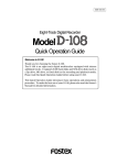
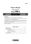
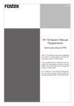
8288 442 000
Digital multitrack recorder
Model
Quick Operation Guide
Welcome to the VR800
Thank you for choosing the Fostex digital multitrack recorder Model VR800.
The VR800 is a digital multitrack recorder that is designed to connect to a digital mixing
console equipped with adat digital I/O. For recording media, it uses removable disks, such as
SCSI Zip and MO drive disks, fixed disks, or 3.5-inch E-IDE hard disks, providing you with a
maximum of eight track simultaneous recording and playback.
The VR800 also features high quality recording and playback, and non-destructive editing
thanks to digital recording technology. The superior tonal quality and easy operation of the
VR800, compared to a conventional analog multitracker, will expand your creative musical
world.
Documentation for the VR800 consists of two parts: the Quick Operation Guide (this book)
and the Owner’s Manual. The Quick Operation Guide introduces you to the basic operations
of the multitrack recorder, including “Connecting a SCSI drive,” “Installing the E-IDE hard
disk,” “Formatting a disk,” “Connecting the digital mixer,” “Initial recording,” “Overdubbing,”
“Ping-pong recording,” and “Mixdown,” so that you can start using your new recorder
immediately. The Owner’s Manual provides you with detailed information on the VR800’s
many functions.
Please read both books thoroughly to make the best use of your VR800. And, be sure to read
the “Precautions” and “Notes on Operating the VR800” in the Owner’s Manual.
VR800 Quick Operation Guide
CAUTION:
CAUTION
TO PREVENT ELECTRIC SHOCK, MATCH WIDE BLADE OF
PLUG TO WIDE SLOT, FULLY INSERT.
RISK OF ELECTRIC SHOCK
DO NOT OPEN
ATTENTION:
POUR EVITER LES CHOCS ELECTRIQUES, INTRODUIRE
LA LAME LA PLUS LARGE DE LA FICHE DANS LA BORNE
CORRESPONDANTE DE LA PRISE ET POUSSER JUSQU'
AU FOND.
CAUTION: TO REDUCE THE RISK OF ELECTRIC SHOCK,
DO NOT REMOVE COVER (OR BACK).
NO USER - SERVICEABLE PARTS INSIDE.
REFER SERVICING TO QUALIFIED SERVICE PERSONNEL.
The lightning flash with arrowhead symbol, within an equilateral
triangle, is intended to alert the user to the presence of uninsulated
"dangerous voltage" within the product's enclosure that may be
of sufficient magnitude to constitute a risk of electric shock to
persons.
"WARNING"
The exclamation point within an equilateral triangle is intended to
alert the user to the presence of important operating and
maintenance (servicing) instructions in the literature
accompanying the appliance.
"TO REDUCE THE RISK OF FIRE OR ELECTRIC SHOCK,
DO NOT EXPOSE THIS APPLIANCE TO RAIN OR
MOISTURE."
9. Heat - The appliance should be situated away from heat sources
SAFETY INSTRUCTIONS
such as radiators, heat registers, stoves, or other appliances
(including amplifiers) that produce heat.
1. Read Instructions - All the safety and operating instructions
should be read before the appliance is operated.
10. Power Sources - The appliance should be connected to a power
supply only of the type described in the operating instructions
2. Retain Instructions - The safety and operating instructions
should be retained for future reference.
or as marked on the appliance.
11. Grounding or Polarization - The precautions that should be taken
3. Heed Warnings - All warnings on the appliance and in the
operating instructions should be adhered to.
so that the grounding or polarization means of an appliance is
not defeated.
4. Follow Instructions - All operating and use instructions should
be followed.
12. Power Cord Protection - Power supply cords should be routed
so that they are not likely to be walked on or pinched by items
5. Water and Moisture - The appliance should not be used near
water - for example, near a bathtub, washbowl, kitchen sink,
placed upon or against them, paying particular attention to cords
at plugs, convenience receptacles, and the point where they
laundry tub, in a wet basement, or near a swimming pool, and
the like.
exit from the appliance.
13. Cleaning - The appliance should be cleaned only as
6. Carts and Stands - The appliance should be used only with a
cart or stand that is recommended by the manufacturer.
recommended by the manufacturer.
14. Nonuse Periods - The power cord of the appliance should be
unplugged from the outlet when left unused for a long period of
time.
15. Object and Liquid Entry - Care should be taken so that objects
do not fall and liquids are not spilled into the enclosure through
openings.
16. Damage Requiring Service - The appliance should be serviced
An appliance and cart combination should be moved with care.
Quick stops, excessive force, and uneven surfaces may cause
the appliance and cart combination to overturn.
by qualified service personnel when:
A. The power supply cord or the plug has been damaged; or
B. Objects have fallen, or liquid has been spilled into the
appliance; or
C. The appliance has been exposed to rain; or
D. The appliance does not appear to operate normally or
exhibits a marked change in performance; or
E. The appliance has been dropped, or the enclosure damaged.
7. Wall or Ceiling Mounting - The appliance should be mounted to
a wall or ceiling only as recommended by the manufacturer.
8. Ventilation - The appliance should be situated so that its location
or position dose not interfere with its proper ventilation.
For example, the appliance should not be situated on a bed,
17. Servicing - The user should not attempt to service the appliance
sofa, rug, or similar surface that may block the ventilation
openings; or, placed in a built-in installation, such as a bookcase
beyond that described in the operating instructions.
All other servicing should be referred to qualified service
or cabinet that may impede the flow of air through the ventilation
openings.
personnel.
2
VR800 Quick Operation Guide
Table of Contents
Recording media........................................................................................................................................................4
Using an E-IDE hard disk..........................................................................................................................................4
Notes on handling a E-IDE hard disk...................................................................................................................................4
Installing an E-IDE hard disk in the VR800........................................................................................................................................5
Using a SCSI drive......................................................................................................................................................6
Notes on handling SCSI drive and disk................................................................................................................................6
Connecting a SCSI drive to the VR800..............................................................................................................................................6
Note on connection................................................................................................................................................................7
Formatting (initializing) a disk.................................................................................................................................8
Checking available recording time on a formatted disk..................................................................................................................11
Checking the record mode of the formatted disk............................................................................................................................11
Formatting the disk again..................................................................................................................................................................11
Ejecting a removable disk from the SCSI drive...............................................................................................................................12
Before turning off the power to the VR800.......................................................................................................................................12
Turning on the power again with a removable disk loaded in the SCSI drive...............................................................................12
Notes on using two current drive.........................................................................................................................13
Connecting a mixer..................................................................................................................................................14
Connecting a digital mixer equipped with adat I/O..........................................................................................................................14
Notes for using a digital mixer.............................................................................................................................................14
About changing the digital-in clock setting.........................................................................................................................15
Connecting an analog mixing console............................................................................................................................................15
Basic recording........................................................................................................................................................16
Initial settings......................................................................................................................................................................................16
About sampling frequency................................................................................................................................................................16
Basic recording procedure...............................................................................................................................................................17
Undo and redo recording..................................................................................................................................................................18
Multitrack recording using overdubbing...........................................................................................................19
Ping-pong recording...............................................................................................................................................19
Mixdown............................................................................................................................................................................20
Recording in a new program.................................................................................................................................20
Basic Locate function.............................................................................................................................................21
Playback using the Vari-pitch function...............................................................................................................22
Owner’s manual reference pages........................................................................................................................23
Notes on operating the VR800
<Recording media>
<Damages>
The VR800 is not equipped with recording media for
recording and playback. Please read the section from
page 4 to prepare the recording media to record, playback,
and edit data on the VR800. For more information on a
recording media supported by the VR800, refer to the
“List of the drives with operation guaranteed” in the main
Owner’s Manual.
Fostex is not responsible for any direct or consequential
damages caused by operating the VR800 and/ or a
connected E-IDE or SCSI drive and/ or disk.
<Copyrights>
It is prohibited by law to use materials recorded on the
VR800 from music CDs and/ or video tapes for which
copyrights belong to a third party for commercial concerts,
broadcasts, sales, and/ or distribution, except for your
personal entertainment.
3
VR800 Quick Operation Guide
Recording media
The VR800 is not equipped with recording media (also called “current drive” in this Guide), such as a
hard disk. You need to prepare a current drive to make a recording
The VR800 supports an E-IDE hard disk, and an external SCSI drive (MO, zip, or fixed hard disk drive)
(that can be connected to the SCSI connector on the rear panel of the VR800). (Note: Using an MO, zip,
or fixed disk may limit the number of recording tracks, depending on the disk capacity.)
Be sure to use a drive and a disk with operation guaranteed by Fostex. For more information on disks
supported by the VR800, refer to the “List of drives with guaranteed operation” in the main Owner’s
Manual.
To use an E-IDE hard disk as a current drive, refer to the “Using an E-IDE hard disk” section on the
following page. To use an external SCSI drive, refer to the “Using a SCSI drive” section. If you are using
both types of drives, refer to the “Notes on using two current drives.”
Using an E-IDE hard disk
The following instructions assume that you have already purchased an E-IDE hard disk unit. Prefer the following
items for hard disk installation:
3.5-inch E-IDE hard disk
Brackets and screws
Driver
<Notes on handling a E-IDE hard disk>
* A E-IDE hard disk is a high-precision device. Do not apply any impact to the disk when and after you install it
in the VR800. Do not leave the disk near a device that generates a strong magnetic field. Choose a level and
stable surface for installation. Be careful not to injure yourself. Fostex is not liable for any malfunction or
damage to the hard disk caused by mishandling.
* You need to set the DIP (Jumper) switch on the hard disk to “MASTER” before you install it into the VR800.
If the switch is set to “SLAVE,” the hard disk will not function correctly.
Refer to the instruction manual that came with your hard disk for more information on the DIP (Jumper) switch
setting.
* Malfunction or misuse of the unit may erase the data recorded on hard disk. We recommended that you save
important recordings to DAT (or adat, backup SCSI disk).
Fostex will not be responsible for any damage due to erased data or any consequential damages caused by
the use of the VR800.
4
VR800 Quick Operation Guide
Installing an E-IDE hard disk in the VR800
Follow the steps below to install a 3.5-inch E-IDE hard disk as a current drive in the VR800.
<Caution>
* Before you start, be sure to remove the power cable from the VR800. Also, NEVER let your hands or metal objects touch the
motherboard or the connectors for the hard disk.
* Wear gloves when you install the hard disk. Customers are not expected to touch the bottom part of the VR800, and the
bottom is not designed to prevent injury. Therefore, if you touch the bottom panel with you bare hand while installing the
hard disk, you may be injured. Be sure to follow the correct procedure and pay careful attention to avoid injury.
1
3
Place the VR800 on the flat level surface so
that the bottom of the unit faces up.
Remove the bottom panel of the VR800 by
removing six screws using a screw driver.
Install the hard disk with brackets to the
specified area in the VR800.
At this point, finger-tighten the screws so that you can
fine-adjust the position of the disk when you connect
the cables.
To prevent knobs and controls on the top panel from
being damaged, place a soft cloth beneath the VR800.
Two cables used to connect to the hard disk appear
when you remove the bottom panel.
Tighten the screws lightly using your fingers.
Connection cables
The motherboard side should face up.
4
2
Connect two cables to the hard disk.
As shown in the figure, bend the wider cable to connect
to the disk, then connect the power supply cable
securely. Be sure to follow the figure below to bend the
wider cable correctly. After connecting the cable, tighten
the screws securely.
Use caution
not to let the
disk unit touch
the case of the
VR800.
Install the included brackets on the hard disk
unit.
Use the included four screws to fix the bracket. As shown
in the figure, align the end of the brackets with the rear
end of the disk unit (that is, the opposite end from the
connector side).
Use caution when you bend
the cable. Do not force the
cable into position.
Brackets
5
Connect the plug in the
correct direction.
Replace the bottom panel using the same six
screws.
Re-position the VR800 so that the top panel faces up,
and proceed to the “Formatting a disk” section on page
8.
Hard disk unit
*Place the hard disk so that the motherboard faces up.
5
VR800 Quick Operation Guide
Using a SCSI drive
The VR800 has a SCSI terminal to connect an external SCSI drive, which enables you to use an MO,
zip, or fixed disk as a current disk drive. For more information on SCSI drives supported by the
VR800, refer to the “List of drives with guaranteed operation” in the Owner’s manual.
The following instructions assume that you already have an external SCSI drive and disk.
MO drive & MO disk
SCSI cable
zip drive & zip cartridge
SCSI terminator
* You can also use a fixed SCSI disk.
<NOTE>
Using an MO disk may limit the VR800’s capabilities. For more information, refer to the “Formatting” section on page 9 regarding the
Record mode.
<Notes on handling SCSI drives and disks>
A SCSI drive and its disk are made of precision parts. Follow the instructions below when you handle them.
* Do not drop them or cause a strong impact.
* Do not expose them to strong vibration.
* Do not expose them to substantial changes in temperature or humidity.
* Do not locate them in a dusty place.
* Do not expose them to water.
* Do not place them near any device that generates a strong magnetic field.
Malfunction or misuse of the unit may erase the data recorded on SCSI disks. We recommended that you save
important recordings to DAT, adat or backup SCSI disks.
Fostex will not be responsible for any damage due to erased data or any consequential damages caused by the
use of the VR800.
Connecting a SCSI drive to the VR800
Connect your SCSI drive to the SCSI connector on the rear panel of the VR800. Refer to the following
“Notes on connection” and connect the drive correctly.
SCSI terminator
WORD OUT
SCSI drive
(Current drive)
SCSI
OPTICAL
DATA
OUT
IN
MIDI
OUT
IN
AC IN
POWER
VR800 rear panel
SCSI connector
SCSI cable
6
VR800 Quick Operation Guide
<Note on connection>
* Before making connections, make sure that both the VR800 and the SCSI drive are turned off.
* Up to two SCSI drives may be connected on a SCSI chain with the VR800.
Connect one SCSI drive as a “current drive” for real-time recording/playback. (Refer to “SCSI ID
number setting” below.) Refer to the main Owner’s Manual for more information on connecting a
SCSI drive as a back-up drive.
VR800
SCSI drive
SCSI drive
Current drive
Backup drive
SCSI drive
* The SCSI connector on the VR800 is a 25-pin connector compatible with Macintosh computers.
Use a cable with connectors that confirm to the standards for connecting a SCSI drive.
* The last SCSI drive on the SCSI chain should be terminated. Install a SCSI terminator, or turn the
termination switch to “on” if the drive has a termination switch (like a zip drive).
<SCSI ID number setting>
* Be sure to set the SCSI ID number for the SCSI drive correctly, according to the purpose of the
drive (as a current drive or a back-up drive). The ID setting is very important.
Using the SCSI drive as a current drive.
Using the SCSI drive as back-up drive.
Select any number from 0 to 5, but not “6.”
Select “6.”
After you make the connection, follow the next steps to format a removable or fixed disk in a SCSI
drive.
7
VR800 Quick Operation Guide
Formatting (initializing) a disk
After you make connection, follow the steps below to format (initialize) the E-IDE hard disk (or SCSI
disk) for use a current drive.
The VR800 uses FDMS-3 (Fostex Disk Management System-3) as the recording format. To perform
real time recording and playback on the VR800, you need to format the disk (regardless of whether
the disk has been used). If you format a used disk, first make sure that the disk does not contain any
important data. Formatting a disk erases all existing data. The following procedure assumes that you
are using a removable SCSI drive disk or fixed disk as the current disk. You can follow the same steps to
format a 3.5-inch E-IDE hard disk, except that you should note the following:
When you turn on the power to the VR800 to format an connected E-IDE hard disk, the [Unformat!] message appears, then
changes to the following indication (instead of the [No Disk] message for a SCSI disk).
Other than this indication, the formatting procedure is identical to the one explained below. If you use an E-IDE hard disk as the
current drive, the [IDE] indicator lights up in the [DRIVE] section on the display.
DIGITAL
44.1kHz
DIGITAL
DIGITAL
44.1kHz
SETUP
SURE ?
SYNC OUT
DRIVE
SYNC OUT
A.PUNCH
AUTO
IDE
AUTO
1
DRIVE
SYNC OUT
A.PUNCH
AUTO
DRIVE
IDE
IDE
A.PUNCH
Turn on the power to the connected SCSI drive and the VR800.
If the SCSI connection has been made correctly, the SCSI drive will start running and the display on the VR800 indicates
the [Initial...] (Initialize) message, then the [No Disk] (there is no disk) message. (The following example assumes that a
removable SCSI drive is connected. If you have connected an unformatted fixed disk or 3.5-inch internal hard disk, the
[UnFormat !] message appears instead of the [No Disk] message.)
DIGITAL
44.1kHz
44.1kHz
DIGITAL
ABS
M
S
F
PGM
SYNC OUT
SYNC OUT
DRIVE
DRIVE
SCSI
AUTO
SCSI
A.PUNCH
AUTO
A.PUNCH
<Notes>
* Before attempting to load a disk in the SCSI drive, make sure [No Disk] is shown in the VR800 display.
* If the [Initial...] message and the [No Drive!] message flash alternately, the VR800 dose not recognized the
connected SCSI drive. In this case, turn off the power to both devices. Check to make sure the SCSI
cable is connected securely and that the cable is not defective, then turn on the power to both devices.
2
Insert a disk in the SCSI drive.
If you insert an unformatted disk in a different format in the SCSI drive, the VR800 indicates [Un Format!] on the
display, then shows the [Format ?] (formatting a current drive disk) menu located in Setup mode.
At this time, the SCSI ID number for the drive will appear as shown below ([SCSi id-2), and [SURE?] flashes.
This means that the VR800 has entered the formatting standby mode.
DIGITAL
DIGITAL
44.1kHz
SETUP
SURE ?
SYNC OUT
DRIVE
SYNC OUT
DRIVE
AUTO
A.PUNCH
AUTO
A.PUNCH
SCSI
8
VR800 Quick Operation Guide
3
When [SURE?] appears, press the EXECUTE/YES key.
The VR800 displays [Pls Wait !] (Please Wait !) briefly, and then show the menu for Record mode selection.
Initially, [ADAC 8ch] for Record mode appears. [SURE ?] flashes at the same time.
DIGITAL
DIGITAL
44.1kHz
SETUP
SURE ?
SYNC OUT
DRIVE
AUTO
A.PUNCH
SYNC OUT
DRIVE
AUTO
A.PUNCH
SCSI
SCSI
4
Use the JOG dial to select the desired record mode.
Turn the JOG dial to select the desired record mode from [ADAC 8ch] mode, [Master 8ch] mode, and [Master 4ch] mode.
Select the appropriate mode for the type of the drive (media) used. Refer to the following chart for more information on the
record mode for specific media.
DIGITAL
44.1kHz
SETUP
DIGITAL
44.1kHz
SETUP
DIGITAL
SURE ?
SURE ?
SYNC OUT
DRIVE
AUTO
A.PUNCH
44.1kHz
SETUP
SURE ?
SYNC OUT
DRIVE
AUTO
A.PUNCH
SYNC OUT
DRIVE
AUTO
A.PUNCH
SCSI
SCSI
SCSI
<Record mode>
There are three recording modes available for the current drive.
Record mode
[ADAC 8ch] mode
[Master 8ch] mode
Quantumize
A. D. A. C. (*)
16 bit linear
[Master 4ch] mode
16 bit linear
Sampling Frequency
44.1kHz
44.1kHz
44.1kHz
Recording time
Approx. 67 minutes
Approx. 17 minutes
Approx. 17 minutes
Compatible media
MO disk, zip disk, Fixed disk
3.5-inch E-IDE hard disk
Fixed disk
3.5-inch E-IDE hard disk
MO disk, zip disk, Fixed disk
3.5-inch E-IDE hard disk
Simultaneous 8 track recording by adat digital
input is possible. RECORD TRACK select
keys 1-8 are enabled.
Simultaneous 8 track recording by adat digital
input is possible.
RECORD TRACK select keys 1-8 are enabled.
Recording function
Save/load function
<NOTE>
Simultaneous recording by MO disk is a
maximum two tracks.
<NOTE>
Simultaneous recording by MO disk is a
maximum two tracks.
Save/load is possible only with external SCSI
drives. Save/load is not possible with DAT and
adat.
Simultaneous 4 track recording by adat digital
input is possible. (ch1~ch4)
RECORD TRACK select keys 1-4 are enabled.
Save/load is possible with external SCSI drive,
DAT or adat.
Save/load is possible only with external SCSI
drives or DAT. Save/load is not possible with
adat.
* A. D. A. C. is the next generation digital audio coding technique maximized for multitrack recording, which has been developed by joint research of
Matsushita Electric Industry Corporation and Fostex Corporation.
<Notes>
* Available recording time varies depending on the disk capacity and type. For actual available time for a particular disk,
please refer to the “List of the drives with guaranteed operation” in the Owner’s Manual.
* To cancel the formatting operation, press the EXIT/NO key before proceeding to step 5. Each press of the EXIT/NO key will
return you to the previous display, and finally exit setup mode.
* Use only the above [ADAC 8ch] mode, or [Master 4ch] mode to format removable type disks. Even if it has been formatted
by the [Master 8ch] mode, sufficient recordable area cannot be obtained.
9
VR800 Quick Operation Guide
5
Press and hold down the RECORD button and press the EXECUTE/YES key.
When the VR800 starts formatting, it displays the size of the unformatted area on the disk, and counts down as formatting
progresses. Wait a moment. When the VR800 finishes formatting, it displays [COMPLETED !] and stops accessing the disk
(The access LED turns off.).
6
Press the EXIT/NO key to quit the setup mode.
One Program (*1) is automatically set up after the disk format operation, and “ABS 00M 00S 00F” (ABS time base*2) appears, indicating that the top of the program is located.
Now, you can start recording, playback, and editing on the VR800 using the SCSI disk, or E-IDE hard disk.
Displays sampling frequency.
Temporary title of program 1
automatically set up after formatting.
This section indicates the status of digital input
signals. It continues to flash until you connect a
digital mixing console.
DIGITAL
Top of the program expressed
in ABS time base.
Program number.
Program 1 is set up after formatting.
44.1kHz
ABS
M
S
F
PGM
SYNC OUT
CLK
VR800’s MIDI sync out signal setting
(Default: MIDI clock [CLK])
AUTO
DRIVE
SCSI
A.PUNCH
Indicates that the current drive is the
SCSI type. If the 3.5-inch E-IDE hard
disk is used for the current drive,
[IDE] will light (For details, refer to
the owner’s manual)
This indicator lights up to indicate that the VR800’s digital-in clock
is set to [ASYnC] (asynchronous). It also lights up after you format the disk. (Refer to the “SETUP mode” section in the main
User’s Guide for more information.)
(*1) Program:
You can set up a maximum of 99 Programs, limited by the available space on your hard disk. You can select
any Program to perform recording, playback, and edit (Program Select function). You may also name the
Programs to facilitate managing individual songs (Program Title Edit function). You can delete unnecessary
Programs (Program Delete function). For more information, refer to the Owner’s Manual.
(*2) Time Base:
This document and the Owner’s Manual use the word “Time Base” frequently. This refers to the units to
indicate the current transport position of the recorder, in other words, Absolute Time.
The VR800 also uses MTC (MIDI time code) and BAR/BEAT/CLK (bar/beat/clock). An MTC value is a relative
time value calculated by adding an MTC offset value to the ABS time value. BAR/BEAT/CLK indicates a
position within a song of VR800’s tempo map based on the MIDI clock position pointer. You can switch to any
of these units as follows. For more information on the Time Base, refer to the Owner’s Manual.
• When ABS Time Base appears on the display, hold down the TIME BASE SEL key repeatedly to switch among these units.
10
VR800 Quick Operation Guide
Checking available recording time on a formatted disk
It is a good idea to check the available recording time after you format the disk. The following
procedure assumes that the VR800 has exited Setup mode and is displaying the ABS time, with disk
access stopped.
1
Press the DISP SEL key to change from the ABS time indication to the REMAIN time indication.
The VR800 displays the available recording time and recording space in ABS time base. This time value indicates how many
minutes of data can be recorded on the formatted disk, and how much of the space on the disk can be used for recording. The
REMAIN time values are based on mono track recording. If you wish to record on all eight tracks, you can find out how many
minutes of a song you can record by dividing the REMAIN time value by “8.”
The example at left is the REMAIN display immediately after formatting
a removable type disk in the [ADAC 8ch] mode.
The numbers in the display indicate a remain time of 1 hour 31 minutes
13 seconds or, in disk capacity, 134 MB that can be recorded in mono
track format. For example, if this disk is used to record on all 8 tracks,
about 11 minutes can be recorded.
44.1kHz
DIGITAL
MB
REMAIN
H
M
S
SYNC OUT
CLK
AUTO
2
DRIVE
SCSI
A.PUNCH
Press the DISP SEL key to return to the previous time base display.
Checking the record mode of the formatted disk
Follow the steps below to check the record mode of the formatted disk.
1
While the VR800 is stopped, press the DISP SEL key to display the REMAIN indication, then
press the EXIT/NO key.
As shown in this example, the VR800 displays the record mode of the disk (current drive) for a second, then displays the
previous REMAIN indication.
DIGITAL
44.1kHz
DIGITAL
44.1kHz
MB
REMAIN
DIGITAL
H
M
S
AUTO
MB
REMAIN
H
SYNC OUT
CLK
44.1kHz
MB
REMAIN
M
DRIVE
S
H
SYNC OUT
CLK
SCSI
A.PUNCH
AUTO
DRIVE
SCSI
A.PUNCH
M
S
SYNC OUT
CLK
AUTO
DRIVE
SCSI
A.PUNCH
Formatting the disk again
If you wish to change the recording mode of a formatted disk or to reformat a used disk, you need to set the
VR800 to SETUP mode and use the [Format ?] menu. The procedure assumes that the formatted disk is in the SCSI
drive and the VR800 is stopped, with the ABS time base displayed.
<Note>
SETUP mode includes the [Format?] menu for formatting a disk, and the [Bk Format?] menu for formatting a back-up disk. For more
information, refer to the ‘Formatting a disk” section in the main Owner’s Manual.
1
Press the SETUP key to change to Setup mode.
The VR800 will enter the setup mode, and display the first hierarchy of the setup menu. If this is the first time you access this
menu, the VR800 displays the [Sign. Set ?] (Time signature setting menu).
11
VR800 Quick Operation Guide
DIGITAL
44.1kHz
SETUP
SYNC OUT
CLK
2
DRIVE
SCSI
AUTO
A.PUNCH
Turn the JOG dial to select [Format ?] and press the EXECUTE/YES key.
The VR800 displays the ID number of the connected SCSI drive and flashes [SURE ?].
44.1kHz
DIGITAL
DIGITAL
SETUP
44.1kHz
SETUP
SURE ?
SYNC OUT
CLK
3
DRIVE
SYNC OUT
DRIVE
AUTO
A.PUNCH
SCSI
AUTO
SCSI
A.PUNCH
Use the JOG dial to select the desired record mode.
Ejecting a removable disk from the SCSI drive
Follow the procedure below to eject a removable disk from the SCSI drive after the VR800 exits the setup mode
and disk access has stopped. You cannot eject a removable disk using the eject button on the drive.
1
Press and hold down the SHIFT key and press the EXIT/NO key.
The removable disk will be eject from the current SCSI drive.
Before turning off the power to the VR800
Before turning off the power to the VR800 and the connected SCSI drive, check the following items:
* The SCSI disk is not being accessed. (The ACCESS LED is turned off.)
* The VR800 has exited the setup mode and displays the ABS or BAR/BEAT/CLK time base.
* The output volume of the VR800 all connected audio devices is set to minimum.
Turning on the power again with a removable disk loaded in the SCSI drive
There is no procedure for turning on the power without a removable disk loaded in the SCSI drive but if power is
switched off with a disk, and then power needs to be switched on again, follow the procedure below:
1
First, turn on the power to the SCSI drive loaded with the removable disk.
2
First, make sure that the orange LED on the SCSI drive lights up in green and that the
removable disk is not being accessed, and then turn on the power to the VR800.
12
VR800 Quick Operation Guide
Notes on using two current drives
In addition to using an E-IDE hard disk or a SCSI drive as the sole current drive, you may also use an
E-IDE hard disk installed in the VR800 along with a SCSI drive connected to the unit.
However, note the following points when you use two current drives.
VR800 equipped with a 3.5-inch E-IDE hard disk
SCSI device as the current drive
WORD OUT
SCSI
OPTICAL
DATA
OUT
IN
MIDI
OUT
IN
AC IN
POWER
<Note>
You cannot switch between two current drives after the VR800 is turned on. If you are using only one current drive, turning on the
power to the VR800 will automatically start the drive. However, if you are using an E-IDE hard disk and an external SCSI device
simultaneously, turning on the power to the VR800 will use the SCSI device connected to the SCSI terminal as the current drive.
If you wish to use the E-IDE hard disk as the current drive, turn off the power to the SCSI device BEFORE you turn on the power
to the VR800 or disconnect the SCSI connection.
You can check the display to see which drive is currently used after you turn on the power to the VR800. (Refer to the figure
below.) Make sure that you are using the correct current drive for formatting or real-time recording, playback, or edit.
A SCSI drive is the current drive.
DIGITAL
An E-IDE hard disk is the current drive.
DIGITAL
44.1kHz
44.1kHz
ABS
ABS
M
S
M
F
S
F
PGM
PGM
SYNC OUT
CLK
AUTO
SYNC OUT
CLK
DRIVE
SCSI
AUTO
A.PUNCH
“IDE” lights up.
“SCSI” lights up.
13
DRIVE
SCSI
A.PUNCH
VR800 Quick Operation Guide
Connecting a mixer
The VR800 is a digital multitrack recorder that provides 8-track recording, and is designed to connect to a
digital mixing console equipped with adat digital I/O. You can connect adat I/O connectors from a digital
mixer to the DATA IN/OUT connectors on the VR800 using optical cables. You can also connect an analog
mixer via an optional Model VC-8 (ADAT/ANALOG converter).
<Note>
Be sure to turn off the power to all devices before connecting the mixing console.
Connecting a digital mixer equipped with adat I/O
Connect adat I/O connectors from a digital mixer to the DATA IN/OUT connectors on the VR800 using
optical cables.
CAUTION
Word in
adat in
adat out
METER
OL
-3
-6
-9
-12
-18
-24
-36
-40
L
R
ST BUSS/SOLO
WORD OUT
SCSI
OPTICAL
DATA
OUT
IN
MIDI
OUT
IN
AC IN
POWER
PAGE SELECT
1-8 ANALOG IN
SETUP
SYSTEM
9-16 ADAT IN
EQ/LO
MIDI
17-20 EFF RTN
EQ/LO-MID
GAIN
EQ/HI-MID
GAIN
EQ/HI
GAIN
SELECTED EQ
GAIN
EFF EDIT
EFF1
EQ ON
EFF2
EQ LIBRARY
FREQ
CURRENT SCENE STATUS
Q
FREQ
FREQ
Q
FREQ
Q
EFF LIBRARY
Q
RECALL
STORE
RECALL
STORE
VR800
PAN
PAN
PAN
PAN
PAN
PAN
PAN
PAN
EQ EDIT
EQ EDIT
EQ EDIT
EQ EDIT
EQ EDIT
EQ EDIT
EQ EDIT
EQ EDIT
SOLO
SOLO
SOLO
SOLO
SOLO
SOLO
SOLO
SOLO
SOLO
ON
ON
ON
ON
ON
ON
ON
ON
ON
KEY MODE
ROUTING/
PHASE
PAIR/
GROUP
REC BUSS
SOLO
SCENE MEMORY
RECALL
STORE
MMC SEND
CH VIEW
CHANNEL/
METER
Current Drive
/-1
AC outlet
+1/
EXIT
DATA
+10
+10
+10
+10
+10
+10
+10
+10
0
0
0
0
0
0
0
0
0
-10
-10
-10
-10
-10
-10
-10
-10
-10
-20
-20
-20
-20
-20
-20
-20
-20
-20
-30
-30
-30
-30
-30
-30
-30
-30
-40
-40
-40
-40
-40
-40
-40
-40
-30
ENTER
-40
-
-
-
-
-
-
-
-
-60
-
Digital Mixer
<Notes for using a digital mixer>
* If a digital mixer has a WORD IN connector, be sure to connect the WORD OUT connector on the VR800 to the WORD IN
on the digital mixer as shown in the figure above.
* The default clock setting for the VR800’s digital-in is “asynchronous (ASYnC).” To make recordings on the VR800
connected to a digital mixer, you should usually set the VR800’s clock to “asynchronous” and the digital mixer clock setting
to “word (or digital-in).” If the VR800 is connected to WORD IN on the mixing console, set the clock to “WORD.”
If the console is not equipped with WORD IN, select “digital-in.”
In this connection example, the Vari-pitch function of the VR800 is also enabled.
To edit the digital-in clock setting, use the “Digital input track setting” menu in SETUP mode. (Refer to the <Note> on the
next page.)
Digital Mixing console
VR800
clock
Clock setting:
Digital-in clock:
Asynchronous (default)
Word (or digital-in)
14
VR800 Quick Operation Guide
<About changing the digital-in clock setting>
When you change the VR800 digital-in clock setting from “ASYnC (asynchronous)” to “SYnC (synchronous),” be sure to set
the clock setting of the digital mixer to “internal.” For example, if the VR800 digital-in clock is set to [SynC] and the digital mixer
clock setting to “digital in (or word),” a digital loop will be generated between these two devices, preventing normal recording.
Remember that if the VR800’s digital-in clock is set to [SYnC], the Vari-pitch function will be disabled.
Digital mixing console
VR800
Clock setting:
Internal
Digital-in clock:
Synchronous
clock
<About using a disk that has been used on a different model>
When you set a disk used on a different model as the current drive, the digital-in clock setting defaults to [SYnC (synchronous)]. In this case, check the display when the VR800 starts, and adjust the digital-in clock setting, if necessary. Refer to the
“SETUP mode” in the User’s Guide for more information on the digital-in clock setting.
Connecting an analog mixing console
You may connect an analog mixing console to the VR800 via an optional VC-8 (ADAT/ANALOG converter)
as shown below. In this example, an analog mixing console with eight BUS OUTs is connected to the VR800.
Using the VC-8 enables you to make recordings without re-patching the cables, regardless of whether you
are using a four-BUS OUT or two-BUS OUT analog mixer. (For more information on the VC-8, refer to the
User’s Guide included in the VC-8 package.)
VR800
8
7
6
5
7
6
5
4
3
2
1
4
3
2
1
IN
OUT
IN
AD-12A ONLY
WORD OUT SCSI
12V
OPTICAL
DATA
OUT
IN
MIDI
OUT
IN
AC IN
OPTICAL
OUT
8
DC IN
ANALOG
WORD IN
VC-8
DIGITAL
Current Drive
Analog mixing console
15
AC outlet
POWER
VR800 Quick Operation Guide
Basic recording
After you finish preparing a recording media and connecting a mixer, you can start basic recording
using the VR800.
Initial settings
You need to reset all the controls on the VR800 to their initial settings according to the controls and
switches on the mixer before you proceed to the next step. This procedure is called “Initialize” in
this Guide and in the Owner’s Manual. The button and switches on the VR800 should be reset as
shown below. Remember to “Initialize the VR800” before you start a new session.
Set the RECORD TRACK select keys to
“SAFE.” (The RECORD TRACK select
Locate the top of the selected
program (ABS 0).
key lamps turns off.)
OPTICAL
ACCESS
OL
0
6
12
24
1
2
3
4
5
6
STORE key lamp turns off.
7
8
A SYNC
RECORD TRACK
1
2
START
6
7
8
IN
OUT
EXIT
/ NO
EXECUTE
/ YES
UNDO / REDO
DISP SEL
SETUP
LOCATE
TIME BASE SEL
SCRUB
3
4
5
IN
OUT
END
STORE
EDIT
VARI PITCH
AUTO RTN
AUTO PLAY
AUTO RTN
CLIPBOARD
AUTO PUNCH
PREVIEW
Turn off the Vari-pitch function. ([VARI
HOLD/
PITCH] should not appear on the display.)
EJECT
PGM SEL
SHIFT
P.EDIT
RECORD
AUTO
PUNCH
JOG
SHUTTLE
LOC MEM
STOP
PLAY
REW
F FWD
SCRUB key lamp turns off.
CLIPBOARD PLAY
LOCATE ABS 0
LOCATE REC END
Turn off AUTO PUNCH mode.
(Nothing should appear in the A.
PUNCH section on the display.)
Stop the recorder. (The STOP
button lamp will lights up.)
Turn off AUTO RTN/AUTO PLAY mode.
(Nothing should appear in the AUTO
section on the display.)
About sampling frequency
The VR800 uses a sampling frequency of 44.1kHz. When you record or play back on a VR800 connected to
a digital mixing console, set the sampling frequency of the digital mixer to 44.1kHz. Using a different
sampling frequency on the mixer will prevent normal recording and playback.
16
VR800 Quick Operation Guide
Basic recording procedure
The following explanation assumes that an external SCSI device is connected to the VR800 as the current
drive, and a digital mixer is connected to the DATA IN/OUT connectors of the VR800. (Refer to “Connecting
a SCSI drive” and “Connecting a digital mixer” for details.)
* Initialize the VR800.
* Set the sampling frequency of the digital mixer to 44.1kHz.
OPTICAL
ACCESS
OL
0
6
12
24
1
2
3
4
5
6
7
8
A SYNC
RECORD TRACK
1
2
3
4
5
AUTO RTN
6
7
8
EXIT
/ NO
EXECUTE
/ YES
AUTO PUNCH
Current SCSI drive
START
IN
OUT
STORE
EDIT
VARI PITCH
AUTO RTN
AUTO PLAY
END
IN
OUT
UNDO / REDO
DISP SEL
SETUP
LOCATE
TIME BASE SEL
SCRUB
PREVIEW
HOLD/
3
1, 5
Digital Mixing Console
CLIPBOARD
EJECT
PGM SEL
SHIFT
P.EDIT
STOP
RECORD
2
JOG
SHUTTLE
LOC MEM
PLAY
REW
7
F FWD
CLIPBOARD PLAY
LOCATE ABS 0
LOCATE REC END
AUTO
PUNCH
6
4
1.
Turn on the power to the VR800, SCSI drive, and digital
mixer.
Adjusting the recording level
The VR800 does not have any recording level controls.
You need to adjust the recording level on the device that
outputs recording data. Use the group master faders on
the mixer (faders that control the output level of ADAT
OUT). Set the recording tracks on the VR800 to input
monitoring status so that you can check the level
adjustment.
The VR800 should display the top of Program 1 (Time Base:
ABS). [DIGITAL] lights up on the display. (After formatting,
Program 1 is created, the digital input track is set to [adat],
and the digital-in clock is set to “ASYnC (asynchronous).”
This indicator lights up when the VR800 receives
adat digital signals from the mixer correctly.
DIGITAL
Music instruments
2.
44.1kHz
Press the RECORD button once. (The RECORD button lamp
flashes.)
The “ready” tracks enter the input monitoring status.
As you raise the group output level on the mixer, the level
meter segments of the ready tracks light up. Adjust the
level so that the [0] to [3] level segments of the level meter
light up at the highest peak.
If the [OL] segments of the meter light up, the recording
level is too high. If the recording level is too high on a
digital recorder, the recording signal may distort, unlike
an analog recorder. Especially, if you are recording vocal
or acoustic instruments, the recording level may suddenly
peak.
In this case, you may want to lower the signal peak by
applying a compressor/limiter using an insertion connector.
ABS
M
S
F
PGM
SYNC OUT
CLK
AUTO
DRIVE
SCSI
A.PUNCH
The digital-in clock is set to “ASYnC (asynchronous)” and this indicator lights up.
Selecting a recording track
1.
Press the RECORD TRACK select key of the desired
recording track to set it in READY mode.
The RECORD TRACK select key lamps (red) for tracks in
READY mode start to flash.
17
VR800 Quick Operation Guide
6.
Starting recording
3.
Hold down the RECORD button and press the PLAY button.
The top of the program is immediately located in LOCATE
ABS 0 mode.
The flashing RECORD button lamp and the RECORD TRACK
select key lamp light up steadily.
7.
Stopping recording
4.
Press the PLAY button.
The playback starts from the top of the program. Adjust
the level of input signal at TAPE IN on the mixer and monitor
the sound.
Press the STOP button to finish recording.
When the VR800 is stopped, the [Pls Wait!] message appears
on the display momentarily, then the current position
appears. The ready track lamp flash.
Repeat the procedure described above to record more
tracks (mono track or multiple tracks).
You can record eight different sound sources on the
VR800 simultaneously.
<Note>
Press the STOP button immediately when you finish recording.
Recording unnecessary silence will waste free disk space
required for future edit operations.
<Undo and redo recording>
If you make a mistake or you are not satisfied with the
recording, you can “undo” recording.
Refer to the “Undo and redo recording” section below.
Playing the recorded track
5.
Hold down the STOP button and press the REWIND
button to locate the top of the program (Locate ABS 0).
Press the RECORD TRACK select keys for the ready
tracks to set the tracks in the safe status.
The flashing RECORD TRACK select key lamps turn off.
Undo and redo recording
Everybody makes mistakes. If you make a mistake in recording, you can restore and re-do the data that existed before
the mistake occurred. These functions are called “Undo” and “Redo,” and are executed the UNDO/REDO key on the
control panel. The Undo function enables you to cancel the latest recording or edit and restore the previous state.
Using the Redo function after the Undo function enables you to cancel the Undo operation and restore the latest
recording or edit. These functions have some limitations as described in the <Note> below.
Recorded area
After recording
Undo
Redo
Before recording
<Note>
You can repeatedly use the Undo/Redo functions until you perform one of the following operations:
* You make a new recording.
* You perform a new edit (Copy & Paste, Move & Paste, Auto Punch In/Out, Erase, etc.).
* You turn off the power to the VR800.
* You select a different program.
* You ejecting a removable SCSI disk that is the current drive.
1. After making a recording (or playing back a newly recorded data), press the UNDO/REDO key.
The VR800 displays [Undo!], then [COMPLETED !], and displays the previous time base indication.
Undoing the recording will restore the status obtained before recording.
2. To cancel the undo operation, press the UNDO/REDO key again.
The VR800 displays [Redo!], then [COMPLETED !], and displays the previous time base indication.
Performing the Redo operation will cancel the Undo operation and restore the state obtained after recording.
18
VR800 Quick Operation Guide
Multitrack recording using overdubbing
Multitrack recording is a term for the series of processes in which you record various sound sources to
different tracks and combine them into mixes (L and R). This recording involves an important process
called “overdubbing” in which you record additional sound sources to different tracks while monitoring
the input sound and listening to the record sound. The following procedure assumes that you have already
recorded a rhythm section using a drum machine on track 1.
* Initialize the VR800.
* Do not change the sampling frequency of the digital mixer until you finish the session.
1.
Press the RECORD TRACK select key of the desired
overdubbing track to set in READY mode.
5.
The “ready” track’s RECORD TRACK select key lamp flashes.
2.
Play the sound source accompanying the track 1 sound in
the same way as during the rehearsal.
Press the RECORD button once.
6.
The ready tracks enter input monitoring status, and the
other tracks enter playback monitoring status.
3.
Press the PLAY button to play the program from the
beginning. (Rehearsal)
When you finish overdubbing, stop the VR800, locate
the top of the program, and play the overdubbed sound
as explained in the “Basic Recording and Playback.”
If you are not satisfied with your overdubbing, perform the
Undo function and record again.
Adjust the level of the playback monitoring sound (rhythm
sound on track 1) on the mixer. Play the sound source to
overdub and adjust the recording level on the mixer.
4.
Press and hold down the RECORD button and press
the PLAY button. (Take)
In the same way, overdub the necessary tracks.
When you finish rehearsing, locate the top of the
program for the actual take.
Ping-pong recording
Ping-pong recording is a recording process in which you mix the playback sound of multiple tracks and
record the mix on an empty track. Ping-pong recording enables you to use previously-recorded tracks in a
new recording. In this way, you can overdub more sound sources using a limited number of tracks. The
following procedure explains how to ping-pong record the sound sources recorded on track 1-6 to track 7
and 8. Once you ping-pong record the tracks, you cannot apply effects to the individual tracks. If necessary,
apply effects on the mixer prior to ping-pong recording.
* Initialize the VR800.
* Do not change the sampling frequency of the digital mixer until you finish the session.
1.
Locate the top of program.
6.
2.
Press the hold down the RECORD button on the VR800
and press the PLAY button. (Take)
Press the RECORD TRACK select keys for tracks 7 and
8 to set the tracks to ready mode.
7.
When you finish ping-pong recording, stop the VR800
and play tracks 7 and 8.
3.
Press the RECORD button once. (Rehearsal)
4.
Play the program on the VR800 from the beginning to
send tracks 1-6 sounds to tracks 7 and 8, and adjust the
recording level and the effect balance.
5.
If you are not satisfied with your overdubbing, perform the
Undo function and record again.
After ping-pong recording, you can erase unnecessary data
from tracks 1-6 so that you can use them for new recordings.
Instead of emptying the track, you may use the “Track
Exchange” function to move data to additional tracks.
Refer to the main Owner’s Manual for more information.
Locate the top of the program.
19
VR800 Quick Operation Guide
Mixdown
After overdubbing and ping-pong recording, you can mix all tracks data into two channel stereo data and
record it onto your master recorder. This final process of multitrack recording is called “mixdown.”
The mixdown signals are usually output from the mixer’s STEREO OUT L/R. Connect the master recorder
inputs to the STEREO OUT L/R connectors.
* Initialize the VR800.
* Do not change the sampling frequency of the digital mixer until you finish the session.
1.
Set all tracks to the SAFE status.
5.
Locate the top of the program.
2.
Locate the top of the program on the VR800.
6.
Start recording on the master recorder. (Take)
3.
Set the master recorder to REC-STANDBY mode.
7.
4.
Play the program from the beginning and adjust the
recording level on the master recorder while adjusting
the tonal quality and mix balance of the playback sound
from the mixer. (Rehearsal)
Press the PLAY button on the VR800 to start playing the
program from the beginning.
8.
When mixdown is completed, stop the master recorder
and the VR800.
Adjust the input level on the master recorder so that the
STEREO OUT L/R meters on the mixer respond to the same
degree as the level meters on the master recorder.
Recording in a new program
The explanation so far has been based on one program set up when you format a current drive (E-IDE hard
disk or SCSI disk). You may create up to 99 programs, depending on the available disk space. Multiple
programs do not interfere with each other. You can record, play, and edit each program independently,
which facilitates song management. This section explains how to set up a new program on the disk. Refer
to the main Owner’s Manual for more information regarding programs.
1.
3.
While the VR800 is stopped, hold down the HOLD/> key
and press the STORE key.
The VR800 sets up a new program (program 2) and enters
the [Title Edit] menu in SETUP mode, showing the following
display. In this example, we use the default title. You can
change the title later. Refer to the Owner’s Manual for more
information.
The display indicates [Select PGM!] momentarily, then shows
the title of program 1. The program number and [SURE ?]
flash.
44.1kHz
DIGITAL
Press the EXECUTE/YES key.
44.1kHz
44.1kHz
DIGITAL
SETUP
SURE ?
SYNC OUT
CLK
DRIVE
SYNC OUT
CLK
SCSI
AUTO
A.PUNCH
AUTO
DRIVE
SCSI
PGM
A.PUNCH
SYNC OUT
CLK
SCSI
AUTO
2.
Turn the JOG dial clockwise to select [New PGM?].
4.
The “?” mark of [New PGM ?], and [SURE ?] flash, indicating
that you can set up a new program.
DIGITAL
SYNC OUT
Press the EXIT/NO key.
44.1kHz
Refer to the next page for more information on how to
select the desired program from multiple programs on
the disk.
DRIVE
SCSI
AUTO
A.PUNCH
The VR800 exits SETUP mode, and the top of program 2 in
ABS time base (ABS 0) appears.
SURE ?
CLK
DRIVE
A.PUNCH
20
VR800 Quick Operation Guide
<Note>
Total available recording time is always the maximum available recording time on the disk, regardless of the number of
programs you set on the disk. That is, if you use up the maximum recording time for one program, you will not be able to
record any data on other programs.
<Selecting the desired program from multiple programs>
If you have set up multiple programs on the disk, you first need to select the target program prior to recording,
playback., or edit. To select a program, follow the steps below. Do not select a different program until you finish the
session.
1.While the VR800 is stopped, hold down the HOLD/> key and press the STORE key.
[Select PGM !] appears momentarily, then the number and title of the current program appears.
2.Turn the JOG dial clockwise or counter-clockwise.
The numbers and titles of the programs on the disk appear in turn.
3.Select the desired program number and press the EXECUTE/YES key.
The top of the selected program appears in ABS time base (ABS 0).
Basic Locate function
The Locate function enables you to locate the desired point (move the current position of the recorder)
immediately. There are two locate methods: storing the desired locate point (time or bar/beat/clock value)
into the memory keys, and locating the point without storing it.
This section explains “Locating the top of the program” and “Locating the last recording point in program”
and do not involve storing locate points. Refer to the Owner’s Manual for more information on storing and
locating locate points.
On the VR800, the top of the program on the disk is called “ABS 0” and the recorded area is called “REC END.”
(If the program has no data recorded, ABS 0 corresponds to REC END.) You can use this function to locate the ABS
0 or REC END point immediately, regardless of the current recorder position.
ABS 0
REC END
Recorded area
Locating REC END
Locating ABS 0
Current position
Locating the end of the recorded area of the
program
Locating the top of the program
You can immediately move to the top of the program
(ABS 0), regardless of the current position of the program.
1.
You can immediately move to the end of the recorded
area of the program, regardless of the current position
Press and hold down the STOP button, and press the
REWIND button.
of the program.
1.
RECORD
STOP
PLAY
REW
Press and hold down the STOP button, and press the
F FWD button.
F FWD
RECORD
AUTO
PUNCH
STOP
CLIPBOARD PLAY
LOCATE ABS 0
LOCATE REC END
AUTO
PUNCH
21
CLIPBOARD PLAY
LOCATE ABS 0
LOCATE REC END
PLAY
REW
F FWD
VR800 Quick Operation Guide
Playback using the Vari-pitch function
This section explains how to change the playback speed of the recorder using the Vari Pitch function.
You can set the playback speed in the range of +6.0% in 0.1% increments. The VARI PITCH key turns vari
pitch mode on and off. When the function is turned on, the [VARI PITCH] lights up on the display.
When the function is turned off, the indicates turns off.
* Initialize the VR800.
Procedures vari pitch function
OPTICAL
ACCESS
OL
0
6
12
24
1
2
3
4
5
6
7
8
A SYNC
RECORD TRACK
Digital Mixing Console
1
2
3
4
5
AUTO RTN
6
7
8
EXIT
/ NO
EXECUTE
/ YES
CLIPBOARD
AUTO PUNCH
START
IN
OUT
STORE
EDIT
VARI PITCH
AUTO RTN
AUTO PLAY
END
IN
OUT
UNDO / REDO
DISP SEL
SETUP
LOCATE
TIME BASE SEL
SCRUB
PREVIEW
HOLD/
EJECT
6
2, 7, 8
PGM SEL
SHIFT
5
P.EDIT
RECORD
AUTO
PUNCH
LOC MEM
STOP
PLAY
REW
F FWD
JOG
SHUTTLE
4
CLIPBOARD PLAY
LOCATE ABS 0
LOCATE REC END
3
1
1.
2.
7.
Press the PLAY button to play the VR800.
Press the VARI PITCH key.
The [VARI PITCH] lights up on the display, indicating that
the vari pitch function is turned on.
DIGITAL
8.
44.1kHz
ABS
M
S
F
PGM
VARI PITCH
SYNC OUT
A.PUNCH
Press the VARI PITCH key, press holding down the SHIFT
key.
The current pitch data flashes on the display, indicating
that you can change the pitch data now. (The [0.0] flashes.)
DIGITAL
M
S
<Note>
44.1kHz
ABS
%
.
* Even if the pitch data is 0.0% (no speed change), pressing
the VARI PITCH key will still turn on the vari pitch function.
The speed is not changed, but the vari pitch is turned on.
* The vari pitch function is automatically turned off under the
following conditions:
Flashes
VARI PITCH
SYNC OUT
DRIVE
SCSI
CLK
AUTO
A.PUNCH
4.
5.
Set the desired pitch data using JOG dial.
6.
To continue the playback with the vari pitch function
on, press the EXIT/NO key.
If you wish to play back data at the current vari pitch
again, press the VARI PITCH key to turn the [VARI PITCH]
on.
You can turn the vari pitch function on and off and edit the
pitch data while the VR800 is playing or stopped, but not
during recording. However, if the vari pitch function has
already been turned on and the pitch data was specified
before you started recording, the VR800 will record using
the current vari pitch.
SCSI
AUTO
3.
Lights up
DRIVE
CLK
To turn off vari pitch mode, press the VARI PITCH key.
The [VARI PITCH] turns off, the vari pitch function is
cancelled, and the VR800 resumes playback at normal
speed.Å@
1. You have turned off and on the power to the VR800. (The pitch
data will be reset to 0.0%.)
Adjust the monitor sound level with the mixer.
2. You have set “Slave mode setting” in SETUP mode to ON.
The pitch data previously set will be maintained.
3. You have set a clock of digital in “Digital input track setting” in
SETUP mode to [SYnC] (Synchronous mode).
The VR800 exits vari pitch data edit mode, and continues
playing with the vari pitch you just set.
22
VR800 Quick Operation Guide
Owner’s manual reference pages
This section lists the reference page numbers for the VR800’s functions and features explained in the Owner’s Manual.
Reference pages
Main features..........................................................................................................................................................5
This chapter describes the main features of the VR800.
Precautions.............................................................................................................................................................6
This chapter describes important notes you need to read before you start using the VR800.
Names and functions..............................................................................................................................................7
This chapter explains the functions of the keys, buttons on the top panel, display, and rear panel.
Before operation....................................................................................................................................................20
This chapter describes items you need to remember when you operate the VR800.
Formatting a disk...................................................................................................................................................27
This chapter describes formatting the current and back-up drive disks.
Handling programs...............................................................................................................................................32
This chapter explains how to set up, select, delete, and name the programs.
Punch In/Out..........................................................................................................................................................36
This chapter explains how to perform Auto Punch In/Out and Manual Punch In/Out.
Metronome function..............................................................................................................................................43
This chapter explains how to record using the metronome function of the VR800.
Digital recording using an external digital device..............................................................................................45
This chapter explains to record S/P DIF or adat digital signals using an external digital device.
Storing locate points (edit points)........................................................................................................................48
This chapter explains how to store locate points (edit points).
Locate function......................................................................................................................................................54
This chapter explains how to locate the desired point.
Cue/review function..............................................................................................................................................57
This chapter explains how to use the cue & review function with the REWIND button, the F FWD button,
and the SHUTTLE function, and also explains “digital scrubbing” with the scrub function.
Preview function....................................................................................................................................................59
This chapter describes previewing fade-in and fade-out at the stored locate points (edit points).
Track edit function.................................................................................................................................................61
This chapter describes track edit functions, such as copy & paste, move & paste, erase, and track exchange.
MIDI synchronization............................................................................................................................................68
This chapter describes a synchronization system that uses the MIDI function and the slave functions of
the VR800.
Saving and loading song data..............................................................................................................................75
This chapter explains how to save song data (recorded on current drive) to an external DAT, adat, or a
back-up SCSI disk, and load the saved data back to the current drive.
SETUP mode..........................................................................................................................................................88
This chapter explains how to change the default settings so that the VR800 will operate at the best
condition.
MIDI Implementation chart.................................................................................................................................106
This chart details various MIDI functions.
Fostex System Exclusive Message...................................................................................................................108
23
FOSTEX CORPORATION
3-2-35, Musashino, Akishima-shi, Tokyo 196-0021, Japan
FOSTEX CORPORATION OF AMERICA
15431, Blackburn Ave., Norwalk, CA 90650, U. S. A.
C
PRINTED IN JAPAN MAR. 1999 8288 442000 FX.