1
LED
Power
Status
Link
Internal, 1, 2, 3, 4,
WAN1 and WAN2,
DMZ1 and DMZ2
100
Internal, 1, 2, 3, 4,
WAN1 and WAN2,
DMZ1 and DMZ2
State
Description
Green
The FortiGate unit is on.
Off
The FortiGate unit is off.
Flashing Green
The FortiGate unit is starting up.
Green
The FortiGate unit is running normally.
Off
The FortiGate unit is powered off.
Green
The correct cable is in use and the connected
equipment has power.
Flashing Green
Network activity at this interface.
Off
No link established.
Green
The interface is connected at 100Mbps.
INTERNAL
PWR
STATUS
WAN 1
WAN 2
DMZ 1
DMZ 2
1
2
3
4
LINK 100
LINK 100
LINK 100
LINK 100
LINK 100
LINK 100
LINK 100
LINK 100
A
FortiGate-100A
© Copyright 2007 Fortinet Incorporated. All rights reserved.
Products mentioned in this document are trademarks or registered trademarks of their respective holders.
Regulatory Compliance
FCC Class A Part 15 CSA/CUS
17 January 2007
01-30004-0066-20070117
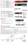
Checking the Package Contents
Connector
Type
Speed
Protocol
Description
Internal
RJ-45
10/100 Base-T
Ethernet
A 4-port switch connection for up to four network
devices or the internal network.
Front
RJ-45
10/100 Base-T
Ethernet
Connection to the Internet.
DMZ1 and
DMZ2
RJ-45
10/100 Base-T
Ethernet
Optional connection to one or two DMZ networks, or
other FortiGate-100A units for high availability (HA).
For details, see the Documentation CD-ROM.
USB
RJ-45
9600 Bps
USB
RS-232
USB
Optional connection to the management computer.
Provides access to the command line interface
(CLI).
Optional connection for the FortiUSB key, modem or
backup operation
WAN 1
WAN 2
DMZ 1
DMZ 2
1
2
3
4
LINK 100
LINK 100
LINK 100
LINK 100
LINK 100
LINK 100
LINK 100
LINK 100
STATUS
A
WAN1 and
WAN2
Console
Ethernet Cables:
Orange - Crossover
Grey - Straight-through
INTERNAL
PWR
RJ-45 to
DB-9 Serial Cable
Power Status WAN
1,2
LED LED
Back
4
3
2
DMZ
1,2
Internal Interface
(4-port switch)
Power Cable Power Supply
1
DC+12V
Console
Internal
USB
Power
Connection
DMZ 2
DMZ2
USB
RS-232 Serial
Connection
Internal Interface
(4-port switch connectors)
WAN 2
DMZ 1
WAN 1
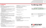
QuickStart Guide
WAN2
DMZ1
INTERNAL
EXTERNAL
WAN1
DMZ
POWER
STATUS
FortiGate-100A
Copyright 2006 Fortinet Incorporated. All rights reserved.
Trademarks
Products mentioned in this document are trademarks.
Documentation
Connecting
Power cable connects to power supply
Optional RS-232 serial cable connects to serial port on management computer
Connect the FortiGate unit to a power outlet and to the internal and external networks.
•
•
•
Place the unit on a stable surface. It requires 1.5 inches (3.75 cm) clearance above and
on each side to allow for cooling.
Plug in power cable to the unit before connecting power.
The Status light flashes while the unit is starting up and turns off when the system is up
and running.
4
3
2
1
DC+12V
Console
USB
Internal
DMZ 2
DMZ 1
WAN 2
WAN 1
Straight-through Ethernet cables connect
to computers on internal network
Optional connection to
1 or 2 DMZ networks
Straight-through Ethernet
cables connect to Internet
(public switch, router or modem)
Planning the Configuration
Before beginning to configure the FortiGate unit, you need to plan how to integrate the unit into your network. Your configuration plan depends on the operating mode you select: NAT/Route
mode (the default) or Transparent mode.
NAT/Route mode
Transparent mode
In Transparent mode, the FortiGate unit is invisible to the network. All of its interfaces are on
In NAT/Route mode, each FortiGate unit is visible to the network that it is connected to. All
the same subnet. You only have to configure a management IP address so that you can make
of its interfaces are on
Internal
configuration changes.
different subnets. Each
network
Internal
Internal network
You would typically use the
interface that is connected
network
192.168.1.99
FortiGate unit in Transparent
to
a
network
must
be
192.168.1.3
Gateway to public network
mode
on a private network
configured
with
an
IP
adInternal
204.23.1.5
10.10.10.2
WAN1
WAN1
Internal
Internet
204.23.1.5
behind an existing firewall or
dress that is valid for that
Internet
Route mode policies
controlling traffic between
Router
10.10.10.3
behind a router. In its default
Router
network.
internal networks
DMZ
Transparent mode configuration,
You would typically use
DMZ
the unit functions as a firewall.
NAT/Route mode when
network
Transparent mode policies
controlling traffic between
No traffic can pass through the
the FortiGate unit is
internal and external networks
FortiGate unit until you add
deployed
as
a
gateway
DMZ network
10.10.10.2
10.10.10.1
NAT mode policies
firewall policies.
between
private
and
public
controlling traffic between
internal and external networks
You can connect up to four network segments to the FortiGate unit to control traffic between
networks. In its default
these network segments.
NAT/Route mode configuration, the unit functions as a firewall. Firewall policies control communications through the
FortiGate unit. No
traffic can pass through the FortiGate unit until you add firewall policies. In NAT/Route mode,
firewall policies can operate in NAT mode or in Route mode. In NAT mode, the FortiGate unit
performs network address translation before IP packets are sent to the destination network.
In Route mode, no translation takes place.
Refer to the Documentation CD-ROM for information on how to control traffic, and how to configure HA, antivirus protection, FortiGuard, Web content filtering, Spam filtering,
intrusion prevention (IPS), and virtual private networking (VPN).
Choosing a Configuration Tool
Web-based manager
Command Line Interface (CLI)
The FortiGate web-based manager is an easy to use management tool. Use it to configure
the administrator password, the interface and default gateway addresses, and the DNS
server addresses.
The CLI is a full-featured management tool. Use it to configure the administrator password,
the interface addresses, the default gateway address, and the DNS server addresses. To
configure advanced settings, see the Documentation CD-ROM.
Requirements:
•
An Ethernet connection between the FortiGate unit and management computer.
•
Internet Explorer 6.0 or higher on the management computer.
Requirements:
•
The DB-9 serial connection between the FortiGate unit and management computer.
•
A terminal emulation application (HyperTerminal for Windows) on the management
computer.
Collecting Information
General settings
NAT/Route Mode
Internal Interface
WAN1
WAN2
DMZ1
DMZ2
IP:
____.____.____.____
Netmask:
____.____.____.____
IP:
____.____.____.____
Netmask:
____.____.____.____
IP:
____.____.____.____
Netmask:
____.____.____.____
IP:
____.____.____.____
Netmask:
____.____.____.____
IP:
____.____.____.____
Netmask:
____.____.____.____
The internal interface IP address and netmask must be valid for the internal network.
Transparent mode
Management IP
IP:
____.____.____.____
Netmask:
____.____.____.____
Administrator password:
Network Settings:
Default Gateway:
____.____.____.____
Primary DNS Server:
____.____.____.____
Secondary DNS Server:
____.____.____.____
A default gateway is required for the FortiGate unit to route connections to the Internet.
Factory default settings
NAT/Route mode
Transparent mode
Internal interface
192.168.1.99
Management IP
WAN1
192.168.100.99
Administrative account settings
0.0.0.0
WAN2
192.168.101.99
User name
admin
DMZ1
10.10.10.1
Password
(none)
DMZ2
0.0.0.0.
The management IP address and netmask must be valid for the network you will be
managing the FortiGate unit from.
Configuring the FortiGate Unit
Web-based Manager
Command Line Interface
1.
1.
2.
3.
4.
Connect the FortiGate internal interface to a management computer Ethernet interface.
Use a cross-over Ethernet cable to connect the devices directly. Use straight-through
Ethernet cables to connect the devices through a hub or switch.
Configure the management computer to be on the same subnet as the internal
interface of the FortiGate unit. To do this, change the IP address of the management
computer to 192.168.1.2 and the netmask to 255.255.255.0.
To access the FortiGate web-based manager, start Internet Explorer and browse to
https://192.168.1.99 (remember to include the “s” in https://).
Type admin in the Name field and select Login.
NAT/Route mode
To change the administrator password
1. Go to System > Admin > Administrators.
2. Select Change Password for the admin administrator and enter a new password.
To configure interfaces
1. Go to System > Network > Interface.
2. Select the edit icon for each interface to configure.
3. Set the addressing mode for the interface. (See the online help for information.)
•
For manual addressing, enter the IP address and netmask for the interface.
•
For DHCP addressing, select DHCP and any required settings.
•
For PPPoE addressing, select PPPoE, and enter the username and password
and any other required settings.
To configure the Primary and Secondary DNS server IP addresses
1. Go to System > Network > Options, enter the Primary and Secondary DNS IP
addresses that you recorded above and select Apply.
To configure a Default Gateway
1. Go to Router > Static and select Edit icon for the static route.
2. Set Gateway to the Default Gateway IP address you recorded above and select OK.
Transparent mode
To switch from NAT/route mode to transparent mode
1. Go to System > Status, select Transparent.
2. Set the Management IP/Netmask to 192.168.1.99/24.
3. Set a default gateway and select apply.
To change the administrator password
1. Go to System > Admin > Administrators.
2. Select Change Password for the admin administrator and enter a new password.
To change the management interface
1. Go to System > Config > Operation Mode.
2. Enter the Management IP address and netmask that you recorded above and select
Apply.
To configure the Primary and Secondary DNS server IP addresses
1. Go to System > Network > Options, enter the Primary and Secondary DNS IP
addresses that you recorded in step 5 and select Apply.
7
2.
3.
Use the RJ-45 to DB9 to connect the FortiGate Console port to the management computer serial port.
Start a terminal emulation program (HyperTerminal) on the management computer.
Use these settings: Baud Rate (bps) 9600, Data bits 8, Parity None, Stop bits 1, and
Flow Control None.
At the Login: prompt, type admin and press Enter twice (no password required).
NAT/Rout mode
1.
2.
3.
4.
Configure the FortiGate internal interface.
config system interface
edit internal
set ip <intf_ip>/<netmask>
end
Configure the FortiGate external interface.
config system interface
edit wan1
set ip <intf_ip>/<netmask>
Configure the primary and secondary DNS server IP addresses.
config system dns
set primary <dns-server_ip>
set secondary <dns-server_ip>
end
Configure the default gateway.
config router static
edit 1
set gateway <gateway_ip>
end
Transparent Mode
1.
2.
Change from NAT/Route mode to Transparent mode and configure the Management IP
address.
config system settings
set opmode transparent
set manageip <mng_ip>/<netmask>
set gateway <gateway_ip>
end
Configure the DNS server IP address.
config system dns
set primary <dns-server_ip>
set secondary <dns-server_ip>
end
Completing the Configuration
Congratulations!
You have finished configuring the basic settings. Your network is now protected from Internetbased threats. To explore the full range of configuration options, see the online help or the
Documentation CD-ROM.
Visit these links for more information and documentation for your Fortinet product.
• Technical Documentation - http://docs.forticare.com
• Fortinet Knowledge Center - http://kc.forticare.com
• Fortinet Technical Support - http://support.fortinet.com