1
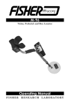
XLT-30
Acoustical Leak Detector
Operating Manual
FISHER
RESEARCH
LABORATORY
CONTENTS
Introduction ........................................................................... pg. 1
Instrument Set ....................................................................... pg. 2
Faceplate & Control Panel ................................................. pg. 4
Operating Instructions ........................................................ pg. 6
Specifications......................................................................... pg. 8
INTRODUCTION
Fisher Research Laboratory has always been a leader in the field
of acoustical leak detection. From the early LT-10 through the
XLT-20, high quality sound amplification has been synonymous with
the name Fisher.
Fishers XLT-30 takes leak detection to a new level. Ultra sensitive
sound microphones, combined with a non-distortion amplification
system and crystal clear audio headphones make the XLT-30 the
leak detector destined to set new standards for the leak
professional.
1
1
INSTRUMENT SET
1. Control Box
All listening and filtering controls for the XLT-30 are contained in this
sturdy housing. The function of each control is described in the section
entitled “Faceplate and Controls”.
2. Big Foot Probe
Also known as the Ground Microphone, this probe is to be used on hard
surfaces, concrete, asphalt, tile, etc. A flexible rubber shield helps prevent
outside sounds from interfering with the sounds from the buried pipe. Depressing the red button near the handle will Mute the audio from the probe
to suppress loud sounds when the probe is moved.
3. Hydrophonic Cylinder Probe
This probe is a direct contact probe designed to make direct connection to
the pipe, or any portion of the pipe that is accessible. Used in any combination of Sound Rods with the T-Handle, pipes can be accessed to distances
up to nearly 6 feet away.
Another feature of the Cylinder Probe is the ability to listen to pipe noise in
pipes that are buried in turf, or soft surfaces. Accurate pipe location is
essential for the placement of the Ground Rods as close to the pipe as possible.
2
INSTRUMENT SET
On top of the Cylinder Probe is a three position toggle switch for Mute,
Listen, and Momentary Listen. As with all Mute controls, learn to use
them wisely.
When tightening the sounds rods to the Hydrophonic Probe, secure the connector with a wrench as to not let it twist. Twisting of that connector could
damage wiring on the inside of the probe.
4. Sound Rods
Two different sizes are included with the XLT-30. One (1) 4 inch rod and
three (3) 24 inch rods give the user various lengths for direct or indirect
contact to pipes.
5. T-Handle
This handle is used primarily with the Cylinder Probe and the sound rods.
6. Headphones
These headphones are designed to deliver the clearest sound with the least
distortion. Unplugging the headphones will turn off the XLT-30. When
the XLT-30 is turned Off, any modifications to Volume, Notch, and Filter
will return to the factory presets.
7. Probe Cable
This cable attaches at the back of the Control Housing to any of the various
probes. Make sure the jack is fully inserted and the lock nut is hand tightend.
8. Carrying Case
Each unit comes with a strong plastic carrying case with foam compartments to store all parts of the XLT-30.
9. Carrying Strap/Housing Mounting Bracket
The attachment system for the XLT-30 consists of a plastic mounting bracket
that slides from the bottom of the control housing up to the bezel around
the faceplate. There are two slots for attaching an adjustable strap that
hangs around the neck of the user.
10. Little Foot Assembly (Accessory)
About the size of a computer mouse, this small handheld probe designed for
areas that the Big Foot Probe can not fit into. The Little Foot assembly is
normally used for leak detection inside buildings. Mute is activated by
depressing button in front of Little Foot Assembly.
3
CONTROL PANEL
POWER
This pad turns the XLT-30 On or Off. When the instrument is turned Off,
all settings, or modifications to settings default to the preset factory settings.
LIGHT
Depress pad to turn the back light On or Off. Prolonged use of the Back
Light will have minimal effect on the battery life of the XLT-30.
VOLUME
Depress pad to modify the Volume of the XLT-30. The arrow keys (Up
arrow/Down arrow) increase or decrease the Volume to the headphones.
NOTCH
This control allows the user to mask or reject a small range of frequency
response. Its purpose is to eliminate a sound (i. e. motor, humming, fans,
etc.) that may be interfering with the leak sound. The Notch setting can be
moved with the Arrow Keys.
FILTER
The XLT-30 has four different filtering modes.
AL (All Frequencies) – This is the No Filter feature of the XLT-30.
No modifications to the signal can be made with the Arrow Keys. Frequency range of the All Frequency setting is from 60 Hz to 6 kHz.
4
CONTROL PANEL
(The following filter modes have a frequency range from 60 Hz to 2.4 kHz)
HI (High Range) – This filtering mode allows the user to adjust the
response in the higher areas of the frequency range. Use the Arrow keys to
increase or decrease this frequency response range.
LO (Low Range) – Similar to the previous filter mode, the Low Pass
filter allows the user to listen to the lower areas of the frequency range.
The Arrow keys are used to increase or decrease this frequency response
range.
FC (Frequency Choice) – This filter could also be called Frequency
Select. This mode allows tuning to the frequency that gives the user the
best response. The Arrow keys are used to move the cursor, selecting a
narrow frequency band of choice
HOLD/MUTE
This dual purpose button is both a Mute control and a Peak Hold
Reset control.
Mute – As the name applies, muting disengages the sound to the
user. There is also a control on all listening microphones. Learn to use this
control to prevent excessive noise to your ears when the probes are moved.
Hold – The display of the XLT-30 will show the highest sound level
recorded. This reading can be reset by depressing this pad. Resetting the
Peak Hold clears earlier readings of the Peak sound.
Arrow Keys
These keys allow features of the XLT-30 to be modified.
RESUME
After any modification has been made to the XLT-30 (VOLUME, NOTCH,
or FILTER), depressing the RESUME will return the display screen back
to a Meter function (Sound Graph).
5
OPERATING INSTRUCTIONS
Set Up
1. Assemble Control Housing, Headset, and your choice of listening probe .
The headset must be plugged in for the XLT-30 to operate.
2. Depress POWER pad to turn On the XLT-30. The XLT-30 goes through
a five second warm up before the touch pads are functional. During this
time, the Display Screen gives information of Battery Level. A reading of
68 or below will activate the “Low Battery” indicator. The XLT-30 does
have a usage buffer between the “Low Battery” indicator and complete system shut down to allow you to complete a job.
3. The XLT-30 always turns On to the default settings. Volume is at the
Medium setting, Filter is in the All Pass (no filter) mode, and the Notch
Control is at the Midway point. The display screen will show the sound
intensity in a bar graph form (Sound Graph) and two digit display.
4. Familiarize yourself where the Mute Buttons (and pad) are. Remember
to Mute the XLT-30 when moving any probe.
5. Depress the VOLUME pad to modify headset volume. Use the ARROW
pads to increase or decrease the volume. The display screen will show the
volume level in a graph form. Depress the RESUME pad to exit Volume
modification and return the Display Screen to the Sound Graph function.
6. Begin your leak detection search.
Modifications During Leak Search
Some leaks are small in size, and unrecognizable, or conditions
are such that very little leak sound can be recognized, so you
may need to make changes to the Filter(s) in order to hear leaks.
Depending upon the type of pipe composition and soil (ground)
type, different filter settings will increase your ability to hear the
leak sound.
Adjustment to the Filter is done by depressing the FILTER pad which
will allow you to scroll through four different filter types. Frequency
range modifications can be made to the HI, LO, and FC filters. As
you are choosing your filter, the display screen will give a visual
display of the filter type being used, and the frequency range of
that filter. After your selection and modification is made, depress
the RESUME pad to return to the Sound Graph function of the
display screen.
6
OPERATING INSTRUCTIONS
Use of the Notch Filter
Occasionally, you may come across a sound that may be masking
or covering your ability to adequately hear any leaks. This may
be caused by nearby motors, fans, or many other annoyances.
(Unfortunately, the most common are sounds caused by
automobiles and traffic). The XLT-30 has a Notch, or reject feature,
that will assist in eliminating that sound from your frequency range.
Depress the NOTCH pad, and use the ARROW pads to move the
cursor to the point where the annoying sound is eliminated or at
its weakest. Depress the RESUME pad to set the Notch function.
(Hint: Depress the FILTER pad to go directly to the FILTER mode.
Now you can choose the type of Filter you wish to use AND still
have the annoying sound Notched).
7
SPECIFICATIONS
Subject to improvement or modification without notice.
Operating frequency Range
All pass mode
60Hz - 6kHz
Filter mode
60Hz - 2.4kHz
Filter Types:
Independent notch filter
Lowpass, Highpass or Bandpass
Gain
95dB
Output Indications:
Audio High performance headphones (64 ohms)
Visual LCD bargraph and 2-digit numeric display
Battery Test
Automatic
Battery Type
Two 9 Volt alkaline
Battery Life
50 Hours (approximate)
Weight
Housing 1.2 lbs.
Bigfoot Sensor 4.5 lbs.
Case Dimensions
8-1/4" x 8-1/2" x 32-1/2"
ACCESSORIES
Standard Equipment:
Hard Carrying Case
Operation Manual
Optional Equipment:
Little Foot Assembly
Fisher Research Laboratory does not warrant suitability to specific use.
Fisher Research Laboratory shall in no event be liable for any direct, incidental,
consequential or indirect damages.
8
QUALITY
Fisher detectors are renowned for their quality.
Each detector is hand crafted in the USA with pride
PERFORMANCE
The worldwide underground utility industry relys on Fisher.
Our instruments are durable, dependable, and search deeper..
REPUTATION
Fisher produced the first patented metal detector in 1931. For
over 70 years, the Fisher logo has been a mark of excellence.
2 YEAR W A R R A N T Y
Fisher believes in the products we produce and backs this belief
with a 2 year warranty on all of our industrial instruments.
Warranty may vary outside of the United States.
See your dealer for details
SERVICE
Fisher is committed to providing you, our valued customer, with
superior service. Each and every instrument is rigidly tested and
carefully inspected during assembly and before shipment.
Should you have any questions or problems, contact:
FISHER RESEARCH LABORATORY
200 West Willmott Road.,
Los Banos, California 93635
Tel 209.826.3292 Fax 209.826.0416
www.fisherlab.com
email: [email protected]
for a dealer near you
1.800.M-SCOPE.1 1.800.672.6731
FRL#8700721