1
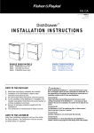
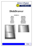
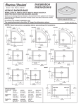
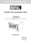
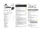
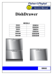
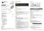
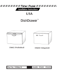
US
part number 526608 J
06/2004
(page 1 of 6)
R
DOUBLE
I N T E G R AT E D PA N E L P R E PA R AT I O N
FOR INTEGRATED DOUBLE MODELS DD603I
R
(NOTE: FOR SINGLE
MODELS, REFER TO BACK OF THIS BOOK)
R
PLEASE NOTE: Your model of
may differ from the model shown in the diagrams. Diagrams have been simplified to enable clearer instruction.
FOLLOW THESE INSTRUCTIONS BEFORE REFERRING TO PRODUCT INSTALLATION INSTRUCTION SHEET P/N 526607.
BEFORE YOU START
open
The Door and Toe Kick Panels
of the
can be
made to match your kitchen
cabinetry. This diagram,
with the addition of your own
measurements will help you
calculate the required panel
sizes.
R
CABINETRY ALIGNMENT
The following calculations
assume:
The top of the Upper Panel is
to be aligned with the top of
the adjacent cabinetry. The
final panel/cabinetry alignment
is achieved by adjusting the
’s feet
R
WIDTH OF ALL PANELS
HEIGHT OF LOWER PANEL
Measure
the width between adjacent door/drawer fronts and write it
in the first box below, then complete the equation. For example:
Measure
door/drawer height (or equivalent) and write it in the first
box below, then complete the equation. For example:
241/4” (616mm)
2x
3/ ” (2.5mm)
32
door clearance
241/16” (611mm)
30” (762mm)
width of all panels
155/8” (398mm)
height of upper panel
2x
5/ ”
16
(8mm)
air gap
5
door clearance
(3/32” (2.5mm) MIN)
width of all panels
(23 7/16” (595mm) MIN)
141/16” (356mm)
height of lower panel
/16
(8mm)
MIN 281/4” (717.5mm) +
height of upper panel
gap between
height of lower panel
panels
(1217/64” (311.5mm) MIN)
HEIGHT OF UPPER PANEL
For example:
155/8” (398mm)
0mm
155/8” (398mm)
standard height
door extension
height of upper panel
R
Important!
5
15 /8 (398mm)
standard height
Note: The ‘Door Extension’
allows for the top of the Upper Panel
to be above the
where required.
The air vent between the Upper and Lower Panels must not be
covered. An air gap of 5/16” (8mm) MUST be provided.
door extension
(0” recommended)
height of upper panel
R
BEFORE YOU START
IMPORTANT
IMPORTANT
INTEGRATED PANEL THICKNESS
WARNING!
Upper and Lower Panel minimum thickness is 5/8” (16mm). Panel
thicknesses above 11/16” (18mm) can be accommodated but product depth
will increase accordingly.
BE SURE THE PRODUCT IS NOT PLUGGED IN.
INTEGRATED PANEL MATERIAL
Important!
Drawer Front material must be suitable for damp conditions
(122oF/50oC @ 80% RH) and adequately sealed to withstand moisture.
Additional protection can be provided by using a “Moisture Resistant
Board”. Taping edges alone may not provide adequate sealing. For
painted panels, radius all rear edges to improve sealing.
The installation of the Panels requires an electrical
connection and must be performed by a suitably
qualified person.
TOE KICK PREPARATION
WIDTH OF TOE KICK PANEL
TOE KICK OPTIONS
Refer to “Width of All Panels” on page 1.
A) The Black Prefinished Toe Kick Panel is supplied. Refer to Installation
Instructions for preparation.
B) The Black Prefinished Toe Kick Panel can also have a front panel of
your choice attached to it using screws or an adhesive.
HEIGHT OF TOE KICK PANEL
C) A Toe Kick panel of any material with thickness from 3/8” - 3/4”
(9-19mm) can be screwed to a plastic Toe Kick Mounting Bracket
(supplied).
Refer to the diagram on page 1. Measure
the height from the top of the
adjacent cabinet door fronts to the floor and write it in the first box below,
then complete the equation.
For example:
TOE KICK PANEL INSTALLATION DEPTH
When using a rectangular Toe Kick, the maximum depth, excluding the
Toe Kick Panel is 25/8” (67mm).
To move the Toe Kick deeper the Toe Kick Panel must have the profile
shown in the diagram below cut out of it. The maximum Toe Kick depth
with the cut out excluding the Toe Kick Panel is 5” (127mm).
341/4” (870mm)
0”
2815/16” (735mm)
15/ ” (12mm)
32
2815/16”
(735mm)
[Height of adjacent
cabinetry]
[Door extension]
[
dimension]
427/32” (123mm)
15/ ”
32
(12mm)
R
[MIN
clearance]
[height of Toe
Kick Panel,
MIN 23/4”
(70.5mm)]
PARTS SUPPLIED
INTEGRATED PARTS KIT part no. 526674
Integrated Rectangular Badge (2)
(Satin Chrome supplied)
p.n 526975
Other Badges Available
Rectangular:
Bright Chrome Kit p.n 527276
Brass Kit p.n 527277
Eliptical:
Black Kit p.n 526683
Satin Chrome Kit p.n 526684
Bright Chrome Kit p.n 527156
Brass Kit p.n 526685
Panel
Preparation
Booklet (1)
Toe Kick
Mounting
Screws (5)
Mounting Bracket (2)
(Upper and Lower)
p.n 526440 & 526441
TOOLS NEEDED
Door Front Seal (2)
p.n 526466
Toe Kick Mounting Bracket (1)
p.n 526682
2
Panel
Mounting
Screws (12)
Safety Glasses, Tape Measure, Pencil, Needle-Nose Pliers, Drill & Phillips
Bit or Phillips Screwdriver, ø 1” (25.4mm) Boring Bit or ø 1” (25.4mm)
Hole Saw, Small Hand or Jig Saw.
R
PANEL PREPARATION INSTRUCTIONS
READ THESE INSTRUCTIONS COMPLETELY AND CAREFULLY.
STEP 1:
BADGE AND HANDLE POSITION
BADGE AND HANDLE POSITIONS
On both Panels, select the Badge position to suit the cabinetry design,
within the available badge zones.
The Badge may be centered on the edge of the badge zone.
The handle position will also need to be taken into account.
STEP 2:
BADGE CUT-OUT & BRACKET REMOVAL
BADGE CUT-OUT
Cut the badge slot in each Panel by drilling two 1” (25.4mm) diameter
holes and cutting out the remaining material between the holes. A hole
center to hole center template is provided on the Mounting Backet.
WARNING!
Be sure the Product is not plugged in.
Important!
(Not shown to scale)
Accuracy is essential when cutting the Badge slot to be sure of a
neat fit to hold the Badge.
REMOVING THE BRACKET
1) To remove the Mounting Brackets withdraw the pins from the Drawer
sides, using a pair of needle-nose pliers.
2) Gently slide the Mounting Bracket off in a downwards and outwards
motion. Disconnect the Mounting Bracket and Badge grounding
wires, also unplug the Badge harness from the Badge Isolator box.
Remove the Badge from the Mounting Bracket.
NOTE: The four 1/8” (3.3mm) holes on the perimeter of the
rectangular recess in the Mounting Bracket can also be used
to define the badge zone.
3
R
PANEL PREPARATION INSTRUCTIONS
STEP 3:
FITTING THE HANDLE AND BADGE
FITTING THE HANDLE
Fit the customer supplied handle.
WARNING!
When mounting the handle, be sure fastenings do not protrude
beyond the back surface of the Panel.
FITTING THE BADGE
Fit a Badge to each Panel by feeding the wires through to the back and
pressing the Badge into the cut out. If needed adhere the Badge to the
Panel with an adhesive.
Feed the Badge wires through the slot in the Mounting Bracket. As the
Mounting Bracket is placed on the rear of the Panel the excess wire must
be pulled through.
STEP 4:
SECURING THE MOUNTING BRACKETS
Each Mounting Bracket is directly screwed to the back of each Integrated
Panel. On a soft surface centralize and align the Upper Mounting Bracket
on the Upper Panel and the Lower Mounting Bracket on the Lower Panel.
Important!
For some materials pilot holes may need to be drilled first before
screwing the Mounting Bracket onto the Panel. Be sure the drill does
not damage the face of the Panel.
Important!
The mounting bracket must not be modified in any way. It is
designed to hold the door front in the correct position to allow
venting.
Important!
The top door front must not extend beyond the bottom of the
mounting bracket. Drying problems and moisture damage may
otherwise occur.
Important!
Break off the tab at the top of the Lower Mounting Bracket, after
Panel has been secured.
Using six of the 5/8” (16mm) screws supplied, secure the Mounting
Bracket to each Panel at the six points shown in the diagram.
NOTE: If the the six outermost slots are not able to be used
to securely fix the Mounting Brackets to the Panel, choose
any six well spaced slots about the Panel.
4
R
PANEL PREPARATION INSTRUCTIONS
STEP 5:
SECURING THE TOE KICK PANEL
NOTE: If using the supplied Black Prefinished Toe Kick,
proceed to Step 6 Grounding the Mounting Brackets and
Connecting the Badge Wires.
Place Toe Kick Panel face down on a soft surface and mark a vertical
center line.
Centralize the plastic Mounting Bracket on top of the Toe Kick Panel.
Align the top of the Bracket with the top of the Panel.
Using 5 of the 5/8” (16mm) screws provided fix the Mounting Bracket to
the Toe Kick Panel.
STEP 6:
GROUNDING THE MOUNTING BRACKETS AND CONNECTING THE BADGE WIRES
WARNING!
Be sure the Product is not plugged in.
1) Plug the green Badge grounding wire onto a Mounting Bracket tab.
Plug the grounding wire from the Product onto the other Mounting
Bracket tab.
2) Connect the Badge plug to the top of the Badge Isolator Box.
Important!
The Badge Isolator Board is an electrostatic sensitive device. Be
sure you are adequately grounded when connecting or disconnecting
the Badge by wearing a grounding strap or by grounding yourself to
the
.
R
5
R
PANEL PREPARATION INSTRUCTIONS
STEP 7:
FITTING THE PANELS TO THE PRODUCT
Fit the assembled Panels by sliding in an inwards and upwards motion.
The rubber seal between the Drawer and Panels must be kept in place.
Secure the Panels by inserting the pins on either side of
the Drawer. Be sure that the rib on the pin is vertical.
NOTE: Do not fit the Toe Kick Panel (or supplied Black
Prefinished Toe Kick) to the
until the Product is in
the cavity.
R
Important!
The gap between doors must be 5/16” (8mm) or drying problems and
moisture damage may occur.
INTEGRATED PANEL PREPARATION IS COMPLETE.
The Product is now ready to install. Refer to Product Installation
Instruction Sheet P/N 526607.
CUSTOMER CARE
If you have any questions concerning the installation of
, please contact your Fisher & Paykel
this
Authorized Service Agent.
R
USA
Fisher & Paykel Appliances
27 Hubble
Irvine
CA 92618
Toll Free
1 888 9 FNP USA
1 888 9 367 872
www.usa.fisherpaykel.com
6
US
part number 526608 J
06/2004
(page 1 of 6)
SINGLE
I N T E G R AT E D PA N E L P R E PA R AT I O N
FOR INTEGRATED SINGLE MODELS DS603I
(NOTE: FOR DOUBLE
MODELS, REFER TO BACK OF THIS BOOK)
PLEASE NOTE: Your model of
may differ from the model shown in the diagrams. Diagrams have been simplified to enable clearer instruction.
FOLLOW THESE INSTRUCTIONS BEFORE REFERRING TO PRODUCT INSTALLATION INSTRUCTION SHEET P/N 526607.
BEFORE YOU START
open
Be sure the Product
is not plugged in.
The Door of the
can be made to match your
kitchen cabinetry. This diagram,
with the addition of your own
measurements will help you
calculate the required panel
sizes.
WIDTH OF THE PANEL
HEIGHT OF THE PANEL
Measure
the width between adjacent door/drawer fronts and write it
in the first box below, then complete the equation.
Measure
door/drawer height (or equivalent) and write it in the first
box below, then complete the equation.
For example:
241/4” (616mm)
2 x 3/32” (2.5mm)
door clearance
241/16” (611mm)
For example:
16” (407mm)
panel width
3/ ” (9mm)
8
air gap
3
2x
155/8” (398mm)
panel height
/8
(9mm)
door clearance
(3/32” (2.5mm) MIN)
panel width
(23 7/16” (595mm) MIN)
gap between
panels
panel height
(155/8” (398mm) MIN)
Note: When the top of the
has to be lower than the
adjacent cabinetry, the Panel can be increased in height.
WARNING!
The air vent between the Panel and the adjacent cabinetry must not
be covered. An air gap of 3/8” (9mm) MUST be provided.
BEFORE YOU START
LOW INSTALLATIONS
Use this diagram if installing the
near floor level.
IMPORTANT
INTEGRATED PANEL THICKNESS
Panel minimum thickness is 16mm. Panel thicknesses above 18mm can
be accommodated but product depth will increase accordingly.
WARNING!
ENSURE THE PRODUCT IS NOT PLUGGED IN.
INTEGRATED PANEL MATERIAL
Drawer Front material must be suitable for damp conditions
(122oF/50oC @ 80% RH) or adequately sealed to withstand moisture.
Additional protection can be provided by using a “Moisture Resistant
Board”. Taping edges alone may not provide adequate sealing. For
painted panels, radius all rear edges to improve sealing.
Important!
The installation of the Panel requires an electrical
connection and must be performed by a suitably
qualified person.
PARTS SUPPLIED
INTEGRATED PARTS KIT part no. 526675
Integrated Rectangular Badge (1)
(Satin Chrome supplied)
p.n 526975
Other Colours Available
Rectangular:
Bright Chrome Kit p.n 527276
Brass Kit p.n 527277
Eliptical:
Black Kit p.n 526683
Satin Chrome Kit p.n 526684
Bright Chrome Kit p.n 527156
Brass Kit p.n 526685
2
Mounting Bracket (1)
p.n 526440
Panel
Preparation
Booklet (1)
Panel
Mounting
Screws (6)
TOOLS NEEDED
Door Front Seal (1)
p.n 526466
Safety Glasses, Tape Measure, Pencil, Needle-Nose Pliers, Drill & Phillips
Bit or Phillips Screwdriver, ø 1” (25.4mm) Boring Bit or ø 1” (25.4mm)
Hole Saw, Small Hand or Jig Saw.
PANEL PREPARATION INSTRUCTIONS
READ THESE INSTRUCTIONS COMPLETELY AND CAREFULLY.
STEP 1:
BADGE AND HANDLE POSITION
BADGE AND HANDLE POSITIONS
On both Panel, select the Badge position to suit the cabinetry design,
within the available badge zone.
If required, the Badge may be centered on the edge of the badge zone.
The handle position will also need to be taken into account.
STEP 2:
BADGE CUT-OUT & BRACKET REMOVAL
BADGE CUT-OUT
Cut the badge slot in the Panel by drilling two 1” (25.4mm) diameter holes
and cutting out the remaining material between the holes. A hole center
to hole center template is provided on the Mounting Backet.
WARNING!
Be sure the Product is not plugged in.
Important!
(Not shown to scale)
Accuracy is essential when cutting the Badge slot to ensure a neat fit
to hold the Badge.
REMOVING THE BRACKET
1) To remove the Mounting Bracket withdraw the pins from the Drawer
sides, using a pair of needle-nose pliers.
2) Gently slide the Mounting Bracket off in a downwards and outwards
motion. Disconnect the Mounting Bracket and Badge grounding
wires, also unplug the Badge harness from the Badge Isolator box.
Remove the Badge from the Mounting Bracket.
NOTE: The four 1/8” (3.3mm) holes on the perimeter of the
rectangular recess in the Mounting Bracket can also be used
to define the badge zone.
3
PANEL PREPARATION INSTRUCTIONS
STEP 3:
FITTING THE HANDLE AND BADGE
FITTING THE HANDLE
Fit the customer supplied handle.
WARNING!
When mounting the handle, be sure fastenings do not protrude
beyond the back surface of the Panel.
FITTING THE BADGE
Fit the Badge to the Panel by feeding the wires through to the back and
pressing the Badge into the cut out. If needed adhere the Badge to the
Panel with an adhesive.
Feed the Badge wires through the slot in the Mounting Bracket. As the
Mounting Bracket is placed on the rear of the Panel the excess wire must
be pulled through.
STEP 4:
SECURING THE MOUNTING BRACKETS
The Mounting Bracket is directly screwed to the back of the Integrated Panel.
On a soft surface centralize and align the Mounting Bracket on the Panel.
Important!
For some materials pilot holes may need to be drilled first before
screwing the Mounting Bracket onto the Panel. Be sure the drill does
not damage the face of the Panel.
Important!
The mounting bracket must not be modified in any way. It is designed
to hold the door front in the correct position to allow venting.
Important!
The door front must not extend beyond the bottom of the mounting
bracket. Drying problems and moisture damage may otherwise occur.
Using six of the 5/8” (16mm) screws supplied, secure the Mounting Bracket
to each Panel at the six points shown in the diagram.
NOTE: If the the six outermost slots are not able to be used to
securely fix the Mounting Brackets to the Panel, choose any
six well spaced slots about the Panel.
4
PANEL PREPARATION INSTRUCTIONS
STEP 5:
GROUNDING THE MOUNTING BRACKETS
WARNING!
Be sure the Product is not plugged in.
Plug the green Badge grounding wire onto a Mounting Bracket tab. Plug
the grounding wire from the Product onto the other Mounting Bracket tab.
WARNING!
The mounting bracket MUST be grounded.
STEP 6:
CONNECTING THE BADGE WIRES
WARNING!
Be sure the Product is not plugged in.
Important!
The Badge Isolator Board is an electrostatic sensitive device. Be sure
you are adequately grounded when connecting or disconnecting the
Badge by wearing an grounding strap or by grounding yourself to the
.
Connect the Badge plug to the top of the Badge Isolator Box.
5
PANEL PREPARATION INSTRUCTIONS
STEP 7:
FITTING THE PANELS TO THE PRODUCT
Fit the assembled Panel by sliding in an inwards and upwards motion. The
rubber seal between the Drawer and Panel must be kept in place.
Secure the Panel by inserting the pins on either side of
the Drawer. Be sure that the rib on the pin is vertical.
Important!
The airflow gap between the bottom of the door panel and adjacent
cabinetry must be 3/8” (9mm) or drying problems and moisture
damage may occur.
INTEGRATED PANEL PREPARATION IS COMPLETE.
The Product is now ready to install. Refer to Product Installation
Instruction Sheet P/N 526607.
CUSTOMER CARE
If you have any questions concerning the installation of
, please contact your Fisher & Paykel
this
Authorized Service Agent.
USA
Fisher & Paykel Appliances
27 Hubble
Irvine
CA 92618
Toll Free
1 888 9 FNP USA
1 888 9 367 872
www.usa.fisherpaykel.com
6