1
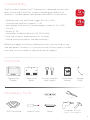
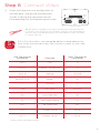
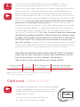
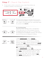
Installation Manual
Model THERM-500
Thank You
Congratulations and thank you for purchasing your new First Alert™ Onelink™
Wi-Fi® Thermostat. You’ve chosen to invest in one of the world’s most advanced
and convenient thermostats for controlling your home’s heating and cooling
systems. The First Alert™ Onelink™ Wi-Fi Thermostat is easy to install, easy to use
and can help save you money on your heating and cooling costs. A typical
installation takes only 20-30 minutes. If you have any problems or questions
during installation please visit www.firstalert.com/thermostats or call customer
service at 800-323-9005.
Online Videos and Tools
VIDEO
Visit www.firstalert.com/thermostats for installation videos, product
feature demonstrations, and full user’s manual.
3
Compatibility
The First Alert™ Onelink™ Wi-Fi Thermostat is designed to work with
5
both 4-Wire and 5-Wire 24V systems, including gas, electric, oil,
WIRE
forced air, variable speed, heat pump and radiant. It can control:
4
• Heating: one, two and three stages (W1, W2, W3)
• Cooling: one and two stages (Y1, Y2)
WIRE
• Heat pump: with auxiliary and emergency heat (Y, W1, O/B)
• Fan (G)
• Power (C, R)
• Humidifier or dehumidifier (HUM, DEHUMM)
• Dual fuel systems (heat pump with furnace)
• Whole-home humidifiers and dehumidifiers
Before you begin installation, determine what your existing wiring
and equipment situation is. If you are unsure of what type of system
you have, you may need to seek professional support.
Contents
Thermostat
Display
Thermostat
Base
Drywall Anchors
and Screws
Installation
Manual
Jumper
Wire
Necessary Tools
Level
WiFi Password
Screw Driver
Pencil
Pliers
Hammer or Drill
(3/16" or 7/32" drill bits)
4
Removal Instructions
Your First Alert™ Onelink™ Wi-Fi Thermostat is designed to work
with most 5-wire and 4-wire systems. 7 wires required for most
VIDEO
multistage systems, systems with cooling, and all electric heating
systems that include humidification / dehumidification equipment.
Look for the following icons for special instructions that apply
specifically to either a 5-wire or 4-wire system. Visit www.firstalert.
com/thermostats for installation and support videos.
5
WIRE
5-Wire System Fan Control
4-Wire System Fan Control
Automatic and Independent
Automatic Only
4
WIRE
Step 1 Power Off Current System
1)
Go to your home’s circuit breaker panel
and switch the furnace and air conditioner
breakers off.
2) To confirm power is off, adjust the
temperature on your current thermostat. If
the system does not respond accordingly,
power has successfully been shut off.
!
WARNING: Failure to follow this step
can result in personal injury and/or
death from shock and electrocution.
Step 2 Remove Faceplate
Remove the faceplate of current system. Most faceplates snap-off or feature
small screws that will need to be removed.
!
5
Side View
WARNING: If you see large thick electric
wires, wire nuts, or if your system is labeled
120V or 240V DO NOT PROCEED. THIS
THERMOSTAT IS NOT COMPATIBLE WITH
THESE SYSTEMS.
Step 3 Label and Disconnect Wires
1)
TIP: Before disconnecting any wires,
take a photo of your current wire
configuration with your mobile device.
One by one, apply the
corresponding sticker (below) to
each wire and disconnect each
from your current thermostat.
2) Be sure to note placement of
jumper cables as you may need
them in the new system.
Wire from the old thermostat
Function terminal marked
Install on the
new thermostat
connector marked
G or F
Fan
G
Y1 or Y
Cooling/Compressor
Y1
W1 or W
Heating
W1/0/B
Rh, R, M, Vr, A
Power
R
C
Common
C
O/B
Rev. Valve
W1/O/B*
W2
2nd Stage Heat
W2
Y2
2nd Stage Cooling
Y2
W3
3rd Stage Heat
W3
OUT - Outdoor Sensor
SENSOR
OUT +
Outdoor Sensor
SENSOR
Wire Color
* O/B is used if your system is a Heat Pump.
NOTE: If the terminal designations on your old thermostat do not match those
on the new thermostat refer to sample wiring diagrams in full user’s manual
at www.firstalert.com/thermostats.
sticker area
6
Installation Instructions
Step 4 Remove Current Backplate
Unscrew the current backplate and remove it
TIP: Wrap the wires around
a pencil or pen to keep them
from falling inside the wall.
from the wall. Be careful not to let the wires fall
into the wall.
Step 5 Mount New Base
1)
Gently separate the display from the base by pulling first from
the bottom and then the top until the two pieces unsnap.
Backplate
REMOVE THE THERMOSTAT BACKPLATE:
Using the Finger Pull Areas, pull the
front housing away from the backplate.
PULL OUT WITH THUMBS IN THESE AREAS.
2) Position the base against your wall, and
determine if wall anchors from current
thermostat align with screw locations of
new base.
3) If base does not align with existing anchor
holes, mark new screw locations with a pencil.
Drywall
Drill 3/16" hole for the anchor
Plaster
Drill 7/32" hole for the anchor
4) Pull wires through opening in base and
secure to the wall using provided screws.
7
Faceplate
TIP: Use a level to ensure
thermostat is properly aligned
before marking screw locations.
Step 6 Connect Wires
1)
Match your previous wire configuration to
the new base. One by one, connect each
wire by inserting the metal end into the
corresponding slot and tightening the screw.
TIP: Use pliers to straighten wire before inserting into new base. Be sure
to cut any excess wire where the insulation extends to the terminal block.
when the wire is installed properly to the terminal block, there should be
no copper exposed.
5
WIRE
For a 5-wire system, use the guide below to help determine
how wires may convert from your current system to your new
THERM-500.
Old Thermostat
Connector
Function
New Thermostat
Connector
G or F
Fan
G
Y1 or Y
Cooling / Compressor
Y1
W1 or W
Heating
W1/O/B
Rh, R, M, Vr, A
Power
R
C
Common
C
O/B
Rev. Valve
W1/O/B*
W2
2nd Stage Heat
W2
Y2
2nd Stage Cooling
Y2
W3
3rd Stage Heat
W3
OUT -
Outdoor Sensor
Sensor
OUT +
Outdoor Sensor
Sensor
* O/B is used in heat pump systems.
8
4
WIRE
The WI-FI thermostat requires a C wire to operate. The C, or
common wire completes the path of 24 VAC power to the
thermostat. Many older mechanical or battery operated thermostats
do not require a C wire and therefore it may not be present or is
present and was not previously utilized. Look for an unused wire
that may be pushed into the wall. If one is found then this wire can
VIDEO
be used as common and connected to the common terminal of the
thermostat. It will also then need to be connected to the common
terminal at the heating/cooling system. All other wires can be
configured exactly as shown in the 5 Wire table above. If an unused
wire cannot be located for C (common) then the G or F (fan) wire
can be used instead. Connect your G or F wire to the common
terminal of the thermostat. This G or F wire will then also need to be
moved to the common terminal at the heating and cooling system.
A jumper wire needs to be placed from Y terminal to G terminal at
the furnace level. This system will not work with an electric heat
plus A/C system. All other wires can be configured exactly as shown
in the 5 Wire table above. Check the video section at www.firstalert.
com/thermostats or call customer service at 800-323-9005.
Note: Not all heating/cooling systems label the 24VAC common C.
Check the full user’s manual or contact the manufacturer to find
out which terminal is 24 VAC common. The optional
Add -A-Wire system shown below can also be utilized.
4-Wire System
G Wire
Function
New Thermostat
Connector
Heating and Cooling
System Connector
G or F
Common
C
C
NOTE: Consult full user’s manual at www.firstalert.com/thermostats if
your wiring configuration is not listed above.
Optional Add-A-Wire™
Available for purchase at www.firstalertstore.com.
Regain independent fan control with a 4-wire
VIDEO
system through the optional purchase of our
Add-A-Wire™ system.
ADD-A-WIRE™
AAW-311
Visit www.firstalert.com/thermostats
for Add-A-Wire installation video.
9
Step 7 Check Dip Switch
1)
Ensure which switch is correct for your system. Dip switches are
1
3
ON
2
1
GAS/EL
O
GAS
HP
B
ELEC
This dip switch configures the thermostat to control
2
3
a conventional gas/electric system or a heat pump. If
your system is anything other than a heat pump, leave
1
ON
2
OR
1
ON
HP
B
ELEC
GAS/EL HP
3
GAS/EL HP
2
ON
GAS/EL
O
GAS
3
located on the back of the thermostat
3
3
this switch set for GAS/EL.
1
3
2
31
HP, this dip switch (O or B) must be set to control
ON
31
2 13 2
W1/O/B terminal will energize in cooling. If B is chosen,
the W1/O/B terminal will energize in heating.
OR
O
2
1 23 3
1
GAS/ELEC
OR
the appropriate reversing valve. If O is chosen, the
B
1
B
ONON
1
ON
OR
OR
1
2
1 23 3
When the GAS/EL HP dip switch is configured for
GAS/EL HP
O
B
GAS/ELEC
ON
2 13 2
ON
ON
ONON
For Heat Pump Only
2
ON
2
2
OR
31
ON
31
ON
OR
GAS/EL HP
O
GAS/ELECB
O
2
O
B
GAS/EL HP
ON
2
OR
3
1
ON
O
B
GAS/EL HP
GAS/ELEC
1. When GAS/EL or HP is set for GAS/EL:
GAS/ELEC
3
2
1
OR
ON
2
1
ON
3
This switch (GAS or ELEC) controls how the
GAS/ELEC
thermostat will control the Fan (G) terminal when
heating. When GAS is chosen, the thermostat will not
energize the Fan (G) terminal, the HVAC will take over
the fan control. When ELEC is chosen the thermostat
will energize the fan in heating.
2. When GAS/EL or HP is set for HP:
This switch (GAS or ELEC) defines the Aux Heat type.
When GAS is chosen, the auxiliary heat will not be
allowed to run during heat pump operation. When
using a Dual Fuel system, set this switch for GAS.
When ELEC is chosen, up to two stages of auxiliary
strip heat will be allowed to run.
10
Step 8 Attach Thermostat Display
1)
Align the pins on the display with the corresponding holes below the
wiring connectors and push the top and the bottom of the plastic
housing enclosing the display until it clicks into place.
!
Display should click into place easily.
If you encounter resistance do not
apply excess force – take the plate
off, check that the pins are straight
and ensure there are no wires in the
way and retry.
Side View
Step 9 Switch Breakers Back On
Turn your furnace and air conditioner breakers back on at your breaker panel.
Step 10 Set Up Thermostat
1)
Follow the on-screen instructions to join your household Wi-Fi
network and setup your thermostat.
2) Visit https://onelink.skyportcloud.com/ from your personal computer
to create an account and access your thermostat remotely for control
away from the home.
3) Download the First Alert™ Onelink™
Thermostat app to your mobile device(s).
NOTE: Your skyport username and login is the same
you used to set up the app.
Available on the
App Store
11
Available on the
Android Market
Troubleshooting
Use the following troubleshooting guide to diagnose common problems.
If you are still having problems or are unsure please visit
www.firstalert.com/thermostats or call customer service at 800-323-9005.
Problem
Possible Cause
Solution
The air conditioning does
not attempt to turn on.
The compressor timer
lockout may prevent
the air conditioner from
turning on for a period of
time
Adjust the Compressor
Min. Off Time to “None”.
The display is blank.
Lack of proper power.
Make sure the power is on
to the furnace and that
you have a 24vac between
R&C.
The air conditioning does
not attempt to turn on.
The cooling setpoint is set
too high.
Lower the cooling setpoint
or lower the cooling
setpoint limit.
The heating does not
attempt to turn on.
The heating setpoint is set
too low.
Raise the heating setpoint
or raise the heating
setpoint limit.
When using a residential
heat pump the heat comes
on instead of the air
conditioning.
The thermostat reversing
valve dip switch is set
incorrectly.
Set the reversing valve dip
switch to ‘O’.
When calling for air
conditioning both the heat
and cool come on.
The thermostat equipment
dip switch is configured
for “HP” and the HVAC
unit is a gas/electric.
Set the equipment dip
switch for “gas”.
First Alert™ Onelink™ Limited Warranty
NOTE: For all limitations and warning, please download the full users manual at www.firstalert.com/thermostats.
PRODUCT LIMITED WARRANTY
BRK Brands, Inc., (“BRK”) the maker of Onelink™ and First Alert™ brand products warrants that for a period of one year from the date of purchase (the “Warranty Period”), this product will be free from defects in material and
workmanship. BRK, at its sole option, will repair or replace this product or any component of the product found to be defective during the Warranty Period. Replacement or repair will be made with a new or remanufactured product
or component. If the product is no longer available, replacement may be made with a similar product of equal or greater value. This is your exclusive warranty. This warranty is valid for the original retail purchaser only from the
date of initial retail purchase and is not transferable. In order to obtain warranty service, you must keep the original sales receipt and proof of purchase in the form of the UPC code from the package. BRK dealers, service centers,
or retail stores selling BRK products do not have the right to alter, modify or any way change the terms and conditions of this warranty.
WARRANTY EXCLUSIONS
Parts and Labor: 1 year limited (warranted parts do not include bulbs, LEDs, and batteries) This warranty does not apply to bulbs, LEDs, and batteries supplied with or forming part of the product. This warranty is invalidated if nonBRK accessories are or have been used in or in connection with the product or in any modification or repair is made to the product. This warranty does not apply to defects or damages arising by use of the product in other than
normal (including normal atmospheric, moisture and humidity) conditions or by installation or use of the product other than in strict accordance with the instructions contained in the product owner’s manual. This warranty does
not apply to defects in or damages to the product caused by (i) negligent use of the product, (ii) misuse, abuse, neglect, alteration, repair or improper installation of the product, (iii) electrical short circuits or transients, (iv) usage
not in accordance with product installation, (v) use of replacement parts not supplied by BRK, (vi) improper product maintenance, or (vii) accident, fire, flood or other Acts of God. This warranty does not cover the performance or
functionality of any computer software included in the package with the product. BRK makes no warranty that the software provided with the product will function without interruption or otherwise be free of anomalies, errors, or
“Bugs.” This warranty does not cover any costs relating to removal or replacement of any product or software installed on your computer. BRK reserves the right to make changes in design or to make additions to or improvements
in its products without incurring any obligations to modify any product which has already been manufactured. BRK will make every effort to provide updates and fixes to its software via its website. This warranty does not cover
any alteration or damage to any other software that may be or may become resident on the users system as a result of installing the software provided. This warranty is in lieu of other warranties, expressed or implied, and BRK
neither assumes nor authorizes any person to assume for it any other obligation or liability in connection with the sale or service of the product. In no event shall BRK be liable for any special or consequential damages arising from
the use of the product or arising from the malfunctioning or non-functioning of the product, or for any delay in the performance of this warranty due to any cause beyond its control. BRK does not make any claims or warranties of
any kind whatsoever regarding the product’s potential, ability, or effectiveness to prevent, minimize, or in any way affect personal or property damage or injury. BRK is not responsible for any personal damage, loss, or theft related
to the product or to its use for any harm, whether physical or mental related thereto. Any and all claims or statements, whether written or verbal, by salespeople, retailers, dealers, or distributors to the contrary are not authorized
by BRK, and do not affect this provision of this warranty. BRK’s responsibility under this, or any other warranty, implied or expressed, is limited to repair, replacement or refund, as set forth above. These remedies are the sole
and exclusive remedies for any breach of warranty. BRK is not responsible for direct, special, incidental, or consequential damages resulting from any breach of warranty or under any other legal theory including but not limited
to, loss profits, downtime, goodwill, damage to or replacement of equipment and property and any costs of recovering, reprogramming or reproducing any program or data stored in or used with a system containing the product
accompanying software. BRK does not warrant the software will operate with any other software except that which is indicated. BRK cannot be responsible for characteristics of their party hardware or software which may effect
the operation of the software included. Except to the extent prohibited by applicable law, any implied warranty of merchantability or fitness for a particular purpose is limited in duration to the duration of the above Warranty Period.
Some states, provinces, or jurisdictions do not allow the exclusion or limitation of incidental or consequential damages or limitations on how long an implied warranty lasts, so the above limitations or exclusion may not apply to
you. This warranty gives you specific legal rights, and you may also have other rights that vary from state to state, or province to province, or jurisdiction to jurisdiction.
OBTAINING SERVICE
If service is required, do not return the product to your place of purchase. In order to obtain warranty service, contact the Consumer Affairs Division at 1-800-323-9005, 7:30 a.m. – 7:00 p.m. Central Standard Time, Monday
through Friday and 8:00 a.m. to 6:00 p.m. Saturday and Sunday. To assist us in serving you, please have the model number and date of purchase available when calling. After contacting the Consumer Affairs Division and it is
determined that the product should be returned for Warranty Service, please mail the product to: BRK Brands, Inc., 3901 Liberty Street Road, Aurora, IL 60504-8122.
12
© 2015 BRK Brands, Inc. All rights reserved. Distributed by BRK Brands, Inc., Aurora, Illinois 60504.
Due to continuing product development, the product inside the packaging may look slightly different
than the one on the package. 1 Year Limited Warranty - see inside for details. First Alert is a trademark
of The First Alert Trust. BRK Brands, Inc. is a subsidiary of Jarden Corporation (NYSE: JAH). Wi-Fi®
is a registered trademark of Wi-Fi Alliance. App Store is a service mark of Apple Inc. Google Play is a
trademark of Google, Inc. Add-A-Wire is a trademark of Venstar, Inc. All rights reserved.
FCC COMPLIANCE STATEMENT
This equipment has been tested and found to comply with the limits for an intentional radiator, pursuant
to Part 15, subpart C of the FCC rules. These limits are designed to provide reasonable protection
against harmful interference in a residential installation. This equipment generates, uses and can radiate
radio frequency energy and, if not installed and used in accordance with the instructions, may cause
harmful interference to radio communications. However, there is no guarantee that the interference
will not occur in a particular installation. If this equipment does cause harmful interference to radio
or television reception, which can be determined by turning the equipment off and on, the user is
encouraged to try to correct the interference by one or more of the following measures:
· Reorient or relocate the receiving antenna.
· Increase the separation between the equipment and receiver.
· Connect the equipment into an outlet on a circuit different from that of the receiver.
· Consult the dealer or an experienced radio or TV technician for help.
Notice: Only peripherals complying with FCC limits may be attached to this equipment. Operation with
noncompliant peripherals or peripherals not recommended by First Alert / BRK Brands, Inc. is likely to
result in interference to radio and TV reception. Changes or modifications to the product, not expressly
approved by First Alert / BRK Brands, Inc., could void the user’s authority to operate the equipment.
We, First Alert / BRK Brands, Inc. declare under our sole responsibility that the device to which this
declaration relates: Complies with Part 15 of the FCC Rules. Operation is subject to the following two
conditions: (1) this device may not cause harmful interference, and (2) this device must accept any
interference received, including interference that may cause undesired operation.
FCC - INDOOR Mobile Radio Information:
To comply with FCC RF exposure limits for general population / uncontrolled exposure, the antenna(s)
used for this transmitter must be installed to provide a separation distance of at least 20 cm from all
persons and must not be co-located or operating in conjunction with any other antenna or transmitter.
M08-0517-002
5/15
Printed in China