1
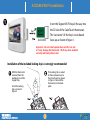
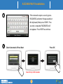
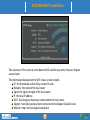
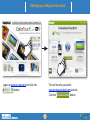
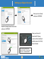
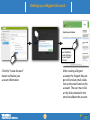
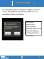
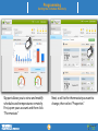
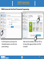
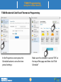
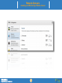
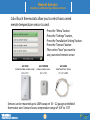
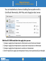
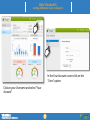
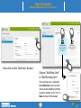
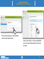
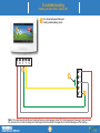
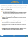
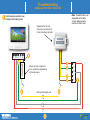
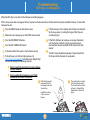
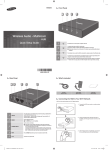
Table of Contents
Skyport Communications Overview
ACC0454 Skyport Wi-Fi Key Installation
Setting up a Skyport Account
Installing the Skyport App
TROUBLE-SHOOTING
Adding Another Wire: Option #1
Adding Another Wire: Option #2
Wi-Fi Key is not Recognized
Upgrading the Firmware via Wi-Fi
Network Connection Errors or Frozen
Screen
Programming: Setting the Schedule
Adobe Air is not Installed
Remotely
Remote Sensors: Installing and Monitoring
a Remote Sensor
User Accounts: Adding Additional Users to
Skyport
Contractor Tips
Skyport Communications Overview
Add Wi-Fi to ColorTouch & get
connected in 5 easy steps
Make sure that the firmware of the ColorTouch thermostat is 2.0 or higher. We
strongly recommend that the firmware be
updated to the latest revision. The firmware
Secure Internet Connection
version may be viewed on the thermostat
by pressing: Menu, ‘down arrow’, Information, My Thermostat. The most current ColorTouch firmware revision
number may be viewed at the bottom of the ColorTouch Assistant
Software home screen.
Computer
Install the Wi-Fi Key and connect to a local router
Go to www.venstar.com and create a Skyport account
a. Enter the 16 digit ID code on the thermostat into Skyport
b. Enter the 6 digit confirmation code on the thermostat into Skyport
After receiving the confirmation email from Skyport Messenger, you must
click on the link in the email to confirm your account to use Skyport
Download the free Skyport mobile apps for Apple or Android smartphones and tablets.
Wireless Router in the Home
Smartphone
iPad or Tablet
ACC0454 Wi-Fi Installation
ACC0454 Wi-Fi Installation
ACC0454
Insert the Skyport Wi-Fi Key all the way into
the SD slot of the ColorTouch thermostat.
The “cut corner” of the Key’s circuit board
faces up as shown in figure 1.
Important - Do not install upside down and force in slot
or it may damage the thermostat. Wi-Fi key when installed
correctly will easily slide in slot.
Installation of the included locking clip is is strongly recommended
With the thermostat
removed from the
backplate, insert the
Skyport Key.
Install the locking
clip as shown in
figure 2.
The Locking Clip is seated
all the way down next to
the circuit board as shown
in figure 3. Reinstall the
thermostat on the backplate.
ACC0454 Wi-Fi Installation
When the Wi-Fi Key is successfullly detected this screen
will appear.
Pressing NO will return the thermostat to the home
screen.
Pressing YES will proceed to step 3.
If Wi-Fi setup screen does not appear go to the
Troubleshooting section page vi.
The thermostat will scan for all
available networks. Select the
appropriate network from the
list on the display.
Scans for up to 90 seconds
ACC0454 Wi-Fi Installation
If the network requires security, press
PASSWORD and enter the password on
the keyboard, then press DONE. If no
security is required, PASSWORD will
not appear. Press NEXT to continue.
Select Automatic & Press Next
Press OK
Scans for up to 90 seconds
ACC0454 Wi-Fi Installation
You are now at the Accessory Info screen* in the Menu.
The status of the thermostat will show that it is
“Connected” to the Wi-Fi LAN.
The ID on this screen will be needed to create an account to
establish a successful connection to Skyport Cloud Services.
*If the Accessory Info screen does not appear then press “Menu”,
the “down arrow”, “Accessories”, and “Accessories Info”.
If this procedure is not successful see page vii.
ACC0454 Wi-Fi Installation
Take a picture of this screen or write down the ID code for easy entry into your Skyport
account later.
The information displayed on the Wi-Fi status screen includes:
ID: the thermostat and wi-fi key custom ID code
Network: the name of the local router
Signal: the signal strength of the local router
IP: the local IP address
Wi-Fi: how long you have been connected to the local router
Skyport: how long you have been connected to the Skyport Cloud Services
Website: http://venstar.skyport.cloud.com
Setting up a Skyport Account
Setting up a Skyport Account
Logon to www.venstar.com and click the
button.
This will transfer you to the
venstar.skyportcloud.com website.
Click the
button
Setting up a Skyport Account
Enter your User Details
and press CONTINUE
Read the Getting Started instructions
and press CONTINUE
Enter your Device ID
from the Wi-Fi Status
screen on the ColorTouch
and then press the “Verify
Device” button
If you need to get back to this
screen click: Menu-->Down Arrow-->
Accessories-->Accessories Info
Setting up a Skyport Account
Your unique Verification Code will
appear on the ColorTouch thermostat after you enter your Device ID.
After entering the Device ID, a unique 6-digit Verification Code will appear on your
thermostat. Your unique Verification Code must be entered into the Skyport New Account Setup page, then press the Confirm Verification Code Button.
Setting up a Skyport Account
Click on the link in
your Validation
email and log in
to your Skyport
Account
Click the “Create Account”
button to finalize your
account information.
After creating a Skyport
account, the Skyport Messenger will send an email validation to the email listed on the
account. The user must click
on the link contained in the
email to validate the account.
Installing the Skyport App
iPhone & iPad Instructions
Go to the App Store on your
iPhone or iPad
Press the Search button
Input “Venstar”
Select Venstar Skyport
Click “FREE” to install
Enter your ID and Password from
the Skyport website.
Android Instructions
Go to the Google Play Store on your
device
Type “Venstar” in the Search Bar
Select Venstar Skyport
Click “Install”
Enter your ID and Password from the
Skyport website.
Wi-Fi Firmware Update
Most, but not all firmware updates may be “through the air” utilizing the local router and Wi-Fi.
On occasion a firmware update with a large amount of data will require the use of an SD
memory card and our ColorTouch Assistant Software.
Update Available (VR2.10)
An update is available for your thermostat, would
you like to install it now? Your thermostat will
restart upon completion.
Update Instructions*
Push the MENU button
Push the SETTINGS button
Push the INSTALLATION SETTINGS button
Push the UPDATE FIRMWARE button
Select YES to update the ColorTouch
* Must have VR 2.06 or later
Programming
Setting the Schedule Remotely
Programming
Setting the Schedule Remotely
Skyport allows you to view and modify
schedules and temperatures remotely.
First, open your account and then click
“Thermostats”
Next, scroll to the thermostat you want to
change, then select “Properties”
T6800 Programming
Setting the Schedule Remotely
T6800 Commercial ColorTouch Thermostat Programming
In the Properties screen press the
Schedule button to view the time
period settings
Make sure the schedule is turned “ON” at
the top of the page and then click “Edit
Schedule”
T6800 Programming
Setting the Schedule Remotely
T6800 Commercial ColorTouch Thermostat Programming
Choose the Occupied period you would
like to change by selecting “Click to
Edit”
Set the mode, temperatures and start/stop
times for your thermostat. Then click
“Enable” program and then “Apply”
T5800 Programming
Setting the Schedule Remotely
T5800 Residential ColorTouch Thermostat Programming
In the Properties screen press the
Schedule button to view the time
period settings
Make sure the schedule is turned “ON” at
the top of the page and then click “Edit
Schedule”
T5800 Programming
Setting the Schedule Remotely
T5800 Residential ColorTouch Thermostat Programming
Choose the Occupied period you would
like to change by selecting “Click to
Edit”
Set the mode, temperatures and start/stop
times for your thermostat. Then click
“Enable” program and then “Apply”
Remote Sensors
Installing and Monitoring a Remote Sensor
Remote Sensors
Installing and Monitoring a Remote Sensor
ColorTouch thermostats allow you to select how a wired
remote temperature sensor is used:
• Press the "Menu" button
• Press the “Settings" button,
• Press the “Installation Setting” button
• Press the “Sensors” button
• Then select “how” you want to
use your wired remote sensor
ACC-TSEN
Indoor/Outdoor remote sensor
(4½” x 2¾”)
ACC-TSENWB
Indoor remote sensor
(2¼” x 1⅜”)
ACC-DSEN
ColorTouch Duct Sensor
(⅛” x ⅜” x 20ft.)
Sensors can be mounted up to 200ft away on 18 ~ 22 gauge unshielded
thermostat wire. Sensors have a temperature range of -40F to 131F
Remote Sensors
Installing and Monitoring a Remote Sensor
Skyport allows you to monitor room air
temperature, supply air temperature
and troubleshoot HVAC units remotely.
First, highlight the Location and then
click “Thermostats”
Next, scroll to the thermostat you want to
monitor and click “Sensors”
Remote Sensors
Installing and Monitoring a Remote Sensor
You can troubleshoot a home or building from anywhere with a
ColorTouch thermostat, a Wi-Fi Key and a Supply air duct sensor.
With the ACC-DSEN installed in the supply duct you can:
1. Compare supply duct temperature to thermostats current heat/cool demand
2. Compare supply duct temperature to actual room temperature on thermostat
3. Compare supply duct temperature to outdoor air temperature
4. See the high & low supply duct temperature history (resets automatically at midnight)
User Accounts
Adding Additional Users to Skyport
[email protected]
[email protected]
[email protected]
User Accounts
Adding Additional Users to Skyport
With Skyport the contractor can be added to their customer’s account and given “View Only” access
for monitoring, or “View and Modify” access to monitor and control the customer’s thermostats.
When a contractor has each of his/her customers add them to their accounts they will be able to
monitor and/or control ALL of their customer’s thermostats from one screen. A powerful Search
function is also available to easily find and access specific thermostats from all of your linked
accounts.
Using Skyport to manage multiple accounts allows a contractor to:
1) Monitor and Control an entire building’s thermostats
2) Provide individual tenants the ability to “View Only” or “View and Modify” the thermostats for
their individual areas
3) Choose who receives e‐mails when the system is not operating correctly, so the owner and/or
contractor do not have to constantly monitor the thermostats to see if the units are running correctly
A Homeowner with an individual Skyport Account can:
1) Give his/her contractor the ability to access their thermostats
2) Give other members of the family access to “View Only” or “View and Modify” the thermostats in
the house
3) Choose who receives e‐mails when the system is not operating correctly, so the owner and/or
contractor do not have to constantly monitor the thermostats to see if the units are running correctly
User Accounts
Adding Additional Users to Skyport
In the Your Account screen click on the
“Users” option
Click on your Username and select “Your
Account”
User Accounts
Adding Additional Users to Skyport
[email protected]
[email protected]
[email protected]
Now click on the “Add User” button
Choose “Add New User”
or “Add Existing User”
If an existing user is selected,
then that user must have the
“Allow to be added to another
account” option set to “Yes” in
their Account Information.
User Accounts
Adding Additional Users to Skyport
Enter the Exisiting User email address
and click the Next button
Select “View Only” or “View and Modify”
access for each thermostat for this user
account
Troubleshooting
Troubleshooting
Adding another Wire: Option #1
Troubleshooting
Adding another Wire: Option #1
This a common problem when replacing a mechanical thermostat or a thermostat powered by batteries. Older thermostats
require four wires, but newer more sophisticated thermostats require a fifth wire. This wire is known as the “Common” wire and
powers the digital display.
Note: Before starting, it is recommended that you take a picture of the original wiring to the old thermostat as reference to help remember what
terminal each thermostat wire was connected to.
Option #1: The easiest and least expensive option is to sacrifice independent control of your indoor fan (wiring diagram on next page)
First, disconnect power from your heating and/or cooling system.
Caution: If your heating and cooling system is powered during the thermostat installation process and you accidentally touch the R (red) power
wire to the C (blue or brown) common wire, you will permanently damage either the equipment fuse or the transformer in the equipment.
After disconnecting power from your heating and/or cooling system, move the wire connected to the G terminal
(typically green) that controls your indoor fan to the C terminal (common) on the thermostat.
At your heating and cooling equipment repeat the same step and move the G terminal wire to the C terminal.
At your heating and cooling equipment place a jumper wire from the Y equipment terminal to the G equipment terminal. This will allow the fan to turn on when the thermostat is calling for cooling or heating but it will not give you independent fan control from the thermostat.
Troubleshooting
Adding another Wire: Option #1
First, disconnect power from your
heating and/or cooling system.
R W C Y G
R
G
W
Y
C
Note: This solution will work for most heating furnaces or heat pumps (about 90% of all equipment) however it may not work
for some electric resistance heating units that require the thermostat to energize the G terminal during a call for heating.
Troubleshooting
Adding another Wire: Option #2
Option #2: Purchase Venstar's ACC0410 Add-A-Wire accessory. Add-A-Wire enables one thermostat wire to control
two thermostat signals. Installation is simple and very inexpensive allowing you to make a 4 wire system into a 5
wire system. Also, multiple Add-A-Wires may be used to turn a 4 wire system into a 6 wire system. Steps 1 and 2
from page ii are identical (wiring diagram on next page):
First, disconnect power from your heating and/or cooling system.
Caution: If your heating and cooling system is powered during the thermostat installation process and you accidentally touch the R (red) power
wire to the C (blue or brown) common wire, you will permanently damage either the equipment fuse or the transformer in the equipment.
After disconnecting power from your heating and/or cooling system, move the wire connected to the G terminal
(typically green) that controls your indoor fan to the C terminal (common) on the thermostat and the C terminal heating and cooling equipment.
As shown in the wiring diagram, use the wire connected to the Y terminal (typically yellow) to connect the Diode ''Y''
wire at the thermostat (blue) to the Add-A-Wire Accessory wire at the equipment (also blue).
At the thermostat connect the Diode ''Y'' Green wire to the G terminal and the Diode ''Y'' Yellow wire to the Y terminal
on the thermostat.
At the equipment connect the Accessory Green wire to the G terminal, the Accessory Yellow wire to the Y terminal, the
Accessory Brown wire to the C terminal, and the Accessory Red wire to the R terminal on the equipment.
Troubleshooting
Adding another Wire: Option #2
First, disconnect power from your
heating and/or cooling system.
Separates the fan and
compressor signals back
to their individual terminals
Note: The Add-A-Wire is not
compatible with 2-Wire
systems and may not be
used on the R or C wires.
R W C Y G
Diode ‘Y’
Add-A-Wire
Allows fan and compressor
to be operated independently
on the same wire
R
G
W
Y
C
Existing thermostat wire
Troubleshooting
Wi-Fi Key is not Recognized
When the Wi‐Fi Key is inserted into the thermostat nothing happens.
If Wi‐Fi setup screen does not appear the Key may be inserted incorrectly or the thermostat may have outdated Firmware. To check the
Firmware Version:
Press the MENU button on the Home Screen
If the firmware is 2.03 or higher and still does not show the
Wi‐Fi setup screen, try taking the Skyport Wi‐Fi Key out
and reinserting it
When the icons come up, press the DOWN arrow button
Press the INFORMATION button
If the Wi‐Fi still does not come up, reset your thermostat
(see the “Factory Default” section in your thermostat
manual) then reinsert and hold the Wi-Fi key in the thermostat
Press the MY THERMOSTAT button
In the lower left of the screen is the Firmware version
If the software is not 2.03 or higher please visit
http://venstar.com/Support/ and click on the “Helpful Tips”
tab to read through the following tutorials:
The Wi‐Fi setup should be displayed. If required, lock the
Wi-Fi key into the thermostat (see below).
“How to install the ColorTouch Assistant software
on your computer”
“How to update the Firmware on your T5800
Residential ColorTouch Thermostat”
With the thermostat
removed from the
backplate, insert the
Skyport Key.
Install the Locking
Clip as shown in
figure 2.
The Locking Clip is seated
all the way down next to
the circuit board as shown
in figure 3. Reinstall the
thermostat on the backplate.
Troubleshooting
Network Connection Errors or Frozen Display
After the network is selected, the thermostat
scans for 90 seconds and the screen displays
“Error unable to connect to network”.
This usually happens because the wrong password was
entered. Try using a smart phone, tablet, or computer to
connect to the Wi‐Fi network. It is recommended that you try
one of these at the same location as the thermostat. If
connection with one of these devices is possible, then the
thermostat should also connect.
You should also look at the Wi‐Fi signal strength by pressing
MENU on the home screen of the thermostat, then the DOWN
arrow to ACCESSORIES and finally ACCESSORY INFO.
If the signal strength is less than 10% you should either move
the Wi‐Fi wireless router closer the thermostat or put in a
Wi‐Fi repeater.
Another suggestion would be to purchase a
newer more powerful router. They typically cost around
$60.00.
New software does not load, display freezes,
or Wi‐Fi Key not recognized.
There are some instances where your thermostat may
need to be rebooted like a computer or Smartphone. This
can be done by turning the power to the thermostat off
and back on.
Grasp the faceplate with both hands
Place thumbs under plastic ridge on bottom of thermostat, and slowly pull the bottom of the faceplate
upwards, without pulling the top.
The thermostat will hinge upwards, disconnecting the
baseplate from the faceplate causing the screen to go
blank, and powering off the thermostat.
Now push the faceplate back onto the baseplate,
securing it once more.
The thermostat will load a white screen with a logo on
it, and then begin starting up.
Once the thermostat finishes starting you have
successfully “Power Cycled” the device.
Troubleshooting
Adobe Air is not Installed
When installing Color Touch Assistant you get an error that
says "ADOBE AIR IS NOT INSTALLED”.
First try installing Adobe Air by clicking the blue
“Install Now” button.
If that fails, reboot your computer, and try the “Install
Now” button again.
After trying to reboot and install still fails, download
Adobe AIR directly from Adobe's website.
http://get.adobe.com/air/
If problems continue to persist, follow the detailed
help offered directly from Adobe at
http://helpx.adobe.com/air/kb/troubleshoot‐airinstallation‐windows
Troubleshooting
Contractor Tips
When your salesman or service technician is in the home have him or her ask the homeowner if they would
like to be able to change the temperature in the house from their smartphone. If they say yes, have the
installer ask the homeowner if they can check out the Wi‐Fi in the house to see if it will support the
ACC0454 Skyport Wi-Fi Key. Then take the smartphone to the vicinity of the thermostat and try to connect
to the homeowner’s Wi‐Fi network. The installer may have to ask for the Wi‐Fi password. Next, by going to
the settings icon on the iPhone, click on Wi‐Fi, choose the network, and enter the password. At this point
the installer can see if the Wi‐Fi thermostat is going to hook up without any problems. If they can connect
with the iPhone, iPad, etc., then the thermostat will also connect. Have the installer save the network name
and password for the customer.
You can set up a Wi‐Fi thermostat at your office for a customer’s home or office. All you will need is an e‐mail
address (you can get one free from Google) or you can use the customer’s e‐mail address and password if
they choose to provide it. Set the thermostat up using your office Wi‐Fi and password for you router. When
the installer goes out to install the thermostat all he or she will need to do is go to MENU on the home
screen. Press the DOWN arrow and then the ACCESSORIES button. Finally press the SETUP button. The
thermostat will then scan for all the networks in the house. Click on the correct network and enter the password to complete the process.
It is imperative that you have a supply air temperature sensor to troubleshoot and monitor their HVAC
system. In most cases you can use the thermostat wire that goes from the thermostat to the rooftop unit,
furnace, etc. Since the thermostat wire ends at the control panel of the unit, it is a short, easy run to put the
temperature sensor in the supply air. If you only have five wires then you can use one or two Add-A-Wires
(ACC0410) to free up wires for the sensor. If you have a long run from thermostat wire you may not be able
to use the thermostat wire. A separate wire must be run or use shielded wire. There is no way of telling if a
problem exists until you try using the thermostat wire. If the temperature fluctuates two or three degrees
when nothing is running, you will need to use shielded wire.