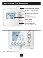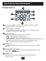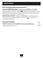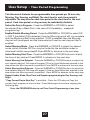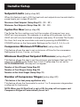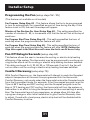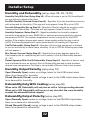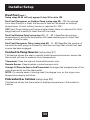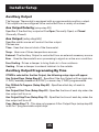
1
SM
CAUTION
Follow the Installation Instructions before proceeding. Set the
thermostat mode to “OFF” prior to changing settings in setup
or restoring Factory Defaults.
FCC Compliance Statement
This equipment has been tested and found to comply with the limits for an
intentional radiator, pursuant to Part 15, subpart C of the FCC rules. These limits
are designed to provide reasonable protection against harmful interference
in a residential installation. This equipment generates, uses and can radiate
radio frequency energy and, if not installed and used in accordance with
the instructions, may cause harmful interference in radio communications.
However, there is no guarantee that the interference will not occur in a particular
installation. If this equipment does cause harmful interference to radio or
television reception, which can be determined by turning the equipment off and
on, the user is encouraged to try to correct the interference by one or more of the
following measures:
• Reorient or relocate the receiving antenna.
• Increase the separation between the equipment and receiver.
• Connect the equipment into an outlet on a circuit different from that of the
receiver.
• Consult the dealer or an experienced radio or TV technician for help.
Notice: Only peripherals complying with FCC limits may be attached to this
equipment. Operation with noncompliant peripherals or peripherals not
recommended by Venstar, is likely to result in interference to radio and TV
reception. Changes or modifications to the product, not expressly approved by
Venstar could void the user’s authority to operate the equipment.
FCC - INDOOR Mobile Radio Information:
To comply with FCC/IC RF exposure limits for general population / uncontrolled
exposure, the antenna(s) used for this transmitter must be installed to provide a
separation distance of at least 20 cm from all persons and must not be co-located
or operating in conjunction with any other antenna or transmitter.
This Device complies with Industry Canada License-exempt RSS standard(s).
Operation is subject to the following two conditions: 1) this device may not
cause interference, and 2) this device must accept any interference, including
interference that may cause undesired operation of the device.
i
Under Industry Canada regulations, this radio transmitter may only operate using
an antenna of a type and maximum (or lesser) gain approved for the transmitter
by Industry Canada. To reduce potential radio interference to other users, the
antenna type and its gain should be so chosen that the equivalent isotropically
radiated power (e.i.r.p.) is not more than that necessary for successful
communication.
Cet appareil est conforme avec Industrie Canada, exempts de licence standard
RSS(s). Son fonctionnement est soumis aux deux conditions suivantes: 1) ce
dispositif ne doit pas causer d’interférences, et 2) ce dispositif doit accepter
toute interférence, y compris les interférences qui peuvent causer un mauvais
fonctionnement de l’appareil.
En vertu des règlements d’Industrie Canada, cet émetteur de radio ne peut
fonctionner en utilisant une antenne d’un type et maximale (ou moins) Gain
approuvé pour l’émetteur par Industrie Canada. Pour réduire les interférences
radio potentielles aux autres utilisateurs, le type d’antenne et son gain doivent
être choisis afin que la puissance isotrope rayonnée équivalente (PIRE) ne est pas
plus de ce qui est nécessaire pour une communication réussie.
We, Venstar, declare under our sole responsibility that the device to which
this declaration relates: Complies with Part 15 of the FCC Rules. Operation is
subject to the following two conditions: (1) this device may not cause harmful
interference, and (2) this device must accept any interference received, including
interference that may cause undesired operation.
This Voyager thermostat has the ability to receive updates to its firmware.
Periodically firmware updates are released by the manufacturer to add features
and/or performance enhancements. This manual was produced reflecting the
most current firmware/feature set at the time of publication, firmware rev. 1.0.
Firmware releases after rev. 1.0 may not be adequately depicted in this manual.
Please refer to the appropriate website or contact your place of purchase to learn
about changes to the thermostat after firmware release 1.0.
MUH-SKYPORT3
ii
Glossary of Terms
Auto-Changeover: A mode in which the thermostat will turn on the
heating or cooling based on room temperature demand.
Cool Setpoint: The warmest temperature that the space should rise
to before cooling is turned on (without regard to deadband).
Deadband: The number of degrees the thermostat will wait, once a
setpoint has been reached, before energizing heating or cooling.
Dehumidify: To reduce the amount of moisture in the air.
Differential: The forced temperature difference between the heat
setpoint and the cool setpoint.
Heat Setpoint: The coolest temperature that the space should drop
to before heating is turned on (without regard to deadband).
Humidify: To increase the amount of moisture in the air.
Icon: The word or symbol that appears on the thermostat display.
Mode: The current operating condition of the thermostat (i.e. Off,
Heat, Cool, Auto, Program On).
Non-Programmable Thermostat: A thermostat that does not have the
capability of running Time Period Programming.
Programmable Thermostat: A thermostat that has the capability of
running Time Period Programming.
Reheat: Running the cooling and 2nd stage strip heaters at the same
time in order to dehumidify the air without cooling down the room
temperature.
Temperature Swing: Same as Deadband.
Time Period Programming: A program that allows the thermostat
to automatically adjust the heat setpoint and/or the cool setpoint
based on the time of the day.
iii
Table of Contents
GET TO KNOW YOUR THERMOSTAT
Get to Know Your Thermostat........................................................ 1
Quick Start...................................................................................... 6
INTALLATION INSTRUCTIONS
Installation Instructions.................................................................. 9
Sample Wiring Diagrams............................................................... 13
Test Operation................................................................................ 16
USER SETUP
Backlight Operation....................................................................... 17
Scrolling Display Options.............................................................. 18
Programming Vacation/Away........................................................ 19
Emergency Heat............................................................................ 19
Wireless Modules.......................................................................... 20
Service Filter.................................................................................. 24
Runtimes........................................................................................ 25
Time Period Programming............................................................ 26
INSTALLER SETUP
Program Mode Operation.............................................................. 28
Setpoint Limits............................................................................... 29
Timers and Deadbands................................................................. 30
Programming Fan Operation......................................................... 31
Comfort Recovery Operation........................................................ 31
Humidification & Dehumidification............................................... 32
Dual Fuel Operation....................................................................... 33
Remote Sensor Operation............................................................. 34
Auxiliary Output............................................................................. 35
Dry Contact Operation.................................................................. 37
Factory Defaults............................................................................ 38
TECHNICIAN SETUP
Sensor Calibration......................................................................... 40
Equipment Testing......................................................................... 40
Advanced Output Testing.............................................................. 40
Advanced Setup Table.................................................................. 41
Troubleshooting............................................................................. 44
INDEX............................................................................................... 45
Get To Know Your Thermostat
Optional Wireless Module
Backlit, Scrolling Display
Backlit Cooler & Warmer
Buttons
Backlit LCD Display
Mode Button
Heat or Cool
Demand Indicator
Red = Heat, Green = Cool
Setup Buttons Behind Door
1
Get To Know Your Thermostat
Setup Buttons
2
Get To Know Your Thermostat
Display Features
2
4
Pm
18:88Am
1
2nd3rd Program ONOFF
Stage
188
Setup Step
188
C L
OO
HI
Day Night
Morning
Evening
6
Fan On
Outdoor
188
3
AUXHEAT
88
3
Lo
5
1 The scrolling display will be used to help you easily navigate
the setup screens in the thermostat.
2 Clock with Day of the Week
Indicates the current time and day. This clock is also used to
program the time period schedules.
3 Mode Indicators
Selects the operational mode of the equipment.
HEAT - Indicates the heating mode.
COOL - Indicates the air conditioning mode.
HEAT & COOL - Indicates the system will automatically change-over between heat and cool modes as the temperature varies.
OFF - Indicates heating and cooling is turned off.
4 Program icon
Indicates that Time Period Programming is running or is enabled
to be set.
5 Room Temperature Display
Indicates the current room temperature and displays the outdoor
temperature when selected.
6 Outdoor icon
Indicates the temperature displayed is from the optional
outdoor sensor.
3
Get To Know Your Thermostat
Display Features
11
Pm
18:88Am
10
8
2nd3rd Program ONOFF
Stage
188
Setup Step
188
C L
OO
HI
Day Night
Morning
Evening
Fan On
Outdoor
188
AUXHEAT
88
Lo
7
12
9
7
7 Desired Set Temperature
Indicates desired room temperature(s). Also displays
the highest and lowest temperatures for the day.
8 Morning, Day, Evening & Night icons
Indicates the day part of the time period program.
9 Wi-Fi icons
Indicates the thermostat is currently connected to the
Local Area Network, via the optional Wi-Fi module.
10 Setup Step icon
Indicates the step number when the thermostat
is in the setup mode.
11 2nd and 3rd Stage icons
Indicates what stage of cooling or heating is currently energized.
12 icon
Indicates the keypad has been locked.
4
Get to know your thermostat
Display Features
Pm
18:88Am
2nd3rd Program ONOFF
Stage
188
Setup Step
16
188
C L
OO
HI
Day Night
Morning
Evening
Fan On
Outdoor
188
13
AUXHEAT
88
15
Lo
14
13 AuxHeat icon
Indicates 2nd stage electric strip heat is being used when the thermostat is programmed for Heat Pump operation. Only the Aux icon will appear during Cool to Dehumidify to indicate
Reheat operation.
14 Lo icon
Indicates the lowest recorded outdoor temperature for the day.*
15 Hi icon
Indicates the highest recorded outdoor temperature
for the day.*
16 Fan On icon
Indicates constant, continuous fan operation.
When Fan On is not lit - indicates the fan will only
operate when necessary to heat or to cool.
* Hi and Lo Temperatures for the day, reset at midnight.
5
Quick Start
During Setup and Programming
Press the WARMER or COOLER buttons to modify the selection.
Press the MODE button to advance and confirm through the setup steps.
Setting the Clock and Day*
*Not available when connected to a Skyport Account
Press the SET CLOCK button. Adjust the clock using the WARMER or
COOLER buttons. Press MODE to advance to the day setting. Adjust
the day using the WARMER or COOLER buttons. Press the SET CLOCK
button to confirm settings.
TIP: To adjust the time by hours press and hold the FAN button while
pressing the WARMER or COOLER buttons.
WARMER
Set
Clock
MODE
COOLER
Selecting the Heat or Cool Mode
Set
Select mode by pressing
the MODE button.
MODE
l k
Heating Only - Only the heating operation will
be controlled by the thermostat in this mode.
Cooling Only - Only the cooling operation will be controlled by the
thermostat in this mode.
Heating or Cooling (Auto-Changeover) - AUTO will automatically select
heat or cool based on room temperature demand.
OFF - OFF indicates both heating and air conditioning systems are turned off.
6
Quick Start
Selecting your desired temperature
AUTO-CHANGEOVER MODE - Pressing the WARMER or COOLER
buttons in Auto mode will adjust both the heat and cool setpoints
simultaneously. To adjust heat and cool setpoints individually, choose
HEAT mode to adjust the heat setpoint and COOL mode to adjust the
cool setpoint, then return to AUTO mode.
HEAT OR COOL MODE - Pressing the WARMER or COOLER buttons
in Heat or Cool mode will adjust only the heat or cool setpoints
individually displayed.
Using the Fan Button
Fan On indicates constant fan operation. You may turn the fan on
even if the thermostat is in the OFF mode. Pressing the FAN button
toggles this feature on or off.
7
FAN ON
AUTO
Quick Start
Viewing the Temperature Sensors
OUTDOOR
OUTDOOR TEMP - Press the OUTDOOR button to view the current
outdoor temperature. The high and low temperatures for the day will
also be displayed. The high and low temperatures reset at 12:00 am.
Press the OUTDOOR button again to return to normal operation.
If the thermostat is connected to Skyport; upon pressing the OUTDOOR button
the scrolling display will read “Forecast”.
The forecasted high and low temperatures for the day will be displayed.
Press the OUTDOOR button again to view any connected wired sensor
(remote or SUPPLY).
Note: If no outdoor sensor is connected, and there isn’t outdoor temperature via
Wi-Fi, then 2 dashes [- -] will appear with the first button press.
REMOTE/SUPPLY TEMP - Press the Accessory Status button to
view linked wireless wired sensors and other accessories.
Press the Accessory Status button to return to the main screen.
Setup step #46 selects the use of the wired temperature sensor.
Viewing the Indoor Humidity Sensor
ACCESSORY
STATUS
HUMIDITY
IMPORTANT: Allow at least 2 minutes after the thermostat is
powered on for the humidity to read correctly.
Press the HUMIDITY button to display the current humidity measured at the
thermostat. The room’s relative humidity is displayed in the top left corner. The
humidification setpoint appears in the larger, center display and can be adjusted
using the WARMER or COOLER buttons. Press the MODE button again to view
and adjust the dehumidification setpoints. Press the HUMIDITY or MODE button
again to confirm settings and return to normal operation.
Note: Due to variations in environmental and equipment conditions, it is not
always possible to achieve the desired humidification or dehumidification
setpoint.
8
Installation Instructions
Remove and Replace the old thermostat
To install the thermostat properly, please follow these step by step
instructions. If you are unsure about any of these steps, call a qualified
technician for assistance.
• Assemble tools: Flat blade screwdriver, wire cutters and wire
strippers.
• Make sure your Heater/Air Conditioner is working properly
before beginning installation of the thermostat.
• Carefully unpack the thermostat.
Save the screws, any brackets,
and instructions.
• Turn off the power to the Heating/Air Conditioning system at
the main fuse panel. Most residential systems have a separate
breaker for disconnecting power to the furnace.
• Remove the cover of the old thermostat.
If it does not come off
easily, check for screws.
• Loosen the screws holding the thermostat base or subbase to
the wall and lift away.
• If you have a smart phone handy, take a photo of the wiring for
future reference.
• Disconnect the wires from the old thermostat. Tape the ends of
the wires as you disconnect them, and mark them with the letter
of the terminal for easy reconnection to the new thermostat.
• Keep the old thermostat for reference purposes, until your new
thermostat is functioning properly.
9
Installation Instructions
Wire Connections
If the terminal designations on your old thermostat do not match those
on the new thermostat, refer to the chart below or the wiring
diagrams that follow.
Wire from the old thermostat
Function terminal marked
Install on the
new thermostat
connector marked
G or F
Fan
G
Y1, Y
Cooling
Y1
W1, W
Heating
W1/0/B
Rh, R, M, Vr, A
Power
R
C
Common
O/B
Rev. Valve
W1/O/B*
C
W2
2nd Stage Heat
W2
Y2
2nd Stage Cooling
Y2
W3
3rd Stage Heat
W3
H, Hum Humidity
HUM
D, Dehum
Dehumidity
DEHUM
Ck1
Dry Contact Switch
DRY CONTACT
CKGND
Dry Contact Switch
DRY CONTACT
* O/B is used if your system is a Heat Pump.
10
Installation Instructions
The Voyager Thermostat Backplate
R
G
W1/O/B
W2
Y1
Y2
W3
HUM
DEHUM
R
G
W1/O/B
W2
Y1
Y2
W3
HUM
DEHUM
To remove the thermostat backplate:
Gently separate the display from
the base by pulling first from one
side, then the other until the two
pieces unsnap. A small screwdriver
may be used, very carefully, to start
seperating the two pieces.
C
AUX
OUTDOOR
SENSOR
REMOTE
SENSOR
DRY
CONTACT
24 VAC return
Fan relay
1st stage heat circuit
2nd stage heat circuit
1st stage compressor relay
2nd stage compressor relay
3rd stage heat circuit
Humidifier conrol circuit
Dehumidifier control circuit
C
24 VAC common
AUX
Aux output
OUTDOOR Outdoor sensor
SENSORconnections
REMOTE
Remote sensor
SENSORconnections
DRY
Dry Contact
CONTACTconnections
IMPORTANT: This thermostat requires both R (24 VAC Return) and
C (24 VAC Common) be connected to the backplate terminals.
11
Installation Instructions
Check Dip Switch
Ensure which switch is correct for your
system. Dip switches are located on the
back of the thermostat.
EL C
B
3
3
GAS
1
1
HP
3
3
ELEC 1. When GAS/EL or HP is set for GAS/EL:
This switch (GAS or ELEC) controls how the
thermostat will control the Fan (G) terminal
in heating mode. When GAS is chosen, the
thermostat will not energize the Fan (G) terminal
in heating. When ELEC is chosen the thermostat
will energize the fan in heating.
ON
2
ON
2
OR
ON
2
ELEC
1
GAS
AS EL
2
O
ELEC
B
HP
ON
GAS
GAS
O
GAS/EL
2. When GAS/EL or HP is set for HP:
This switch (GAS or ELEC) defines the Aux Heat
type. When GAS is chosen, the auxiliary heat
will not be allowed to run during heat pump
operation. When using a Dual Fuel system, set
this switch for GAS. When ELEC is chosen, up to
two stages of auxiliary strip heat will be allowed
to run.
1
1
O
3
3
For Heat Pump Only
B When the GAS/EL or HP dip switch is configured
for HP, this dip switch (O or B) must be set to
control the appropriate reversing valve. If O is
chosen, the W1/O/B terminal will energize in
cooling. If B is chosen, the W1/O/B terminal will
energize in heating.
1
1
ON
OR
2
ON
2
3
3
GAS/EL
OR
ON
B
2
ON
2
O
HP
GAS/EL
HP
This dip switch configures the thermostat to
control a conventional gas/electric system or a
heat pump. If your system is anything other than
a heat pump, leave this switch set for GAS/EL.
12
Installation Instructions
Sample Wiring Diagrams
Conventional Heating and Cooling Systems
3 Wire, Heat Only
4 Wire, Cool Only
R
C
W1/O/B
24VAC Power
24VAC Common
1st Stage Heat
R
C
Y1
G
J1
J2
J3
Gas/Elec
O (not used)
Gas
J1
J2
J3
Residential & Commercial 1 Stage Heating
with no Fan.
=
=
=
Residential & Commercial 1 Stage Cooling.
24VAC Power
24VAC Common
1st Stage Cool
Fan
=
=
=
Gas/Elec
O (not used)
Gas
5 Wire, 1 Stage Cooling, 1 Stage Heat
5 Wire, 1 Stage Cooling, 1 Stage Heat
R
C
W1/O/B
Y1
G
24VAC Power
24VAC Common
1st Stage Heat
1st Stage Cool
Fan
R
C
W1/O/B
Y1
G
24VAC Power
24VAC Common
1st Stage Heat
1st Stage Cool
Fan
J1
J2
J3
Gas/Elec
O (not used)
Gas
J1
J2
J3
Gas/Elec
O (not used)
Electric
Residential & Commercial 1 Stage Cooling,
with 1 stage Gas Heat.
=
=
=
Residential & Commercial 1 Stage Cooling,
with 1 stage Electric Heat.
=
=
=
8 Wire, 2 Stage Cooling, 3 Stage Heat
Residential & Commercial 2 Stage Cooling,
with 3 stage Gas Heat.
R
C
W1/O/B
W2
W3
Y1
Y2
G
24VAC Power
24VAC Common
1st Stage Heat
2nd Stage Heat
3rd Stage Heat
1st Stage Cool
2nd Stage Cool
Fan
J1
J2
J3
Gas/Elec
O (not used)
Gas
=
=
=
13
Installation Instructions
Sample Wiring Diagrams
Heat Pump Systems
5 Wire, 1 Stage Cooling, 1 Stage Heat
6 Wire, 1 Stage Cooling, 2 Stage Heat
R
C
W1/O/B
Y1
R
C
W1/O/B
Y1
Residential & Commercial Heat Pump with
‘O’ Reversing Valve
G
J1
J2
J3
=
=
=
24VAC Power
24VAC Common
Reversing Valve
1st Stage Compressor
(Cool or Heat)
Fan
Heat Pump
O
Gas
Residential & Commercial Heat Pump with
‘O’ Reversing Valve
W2
G
J1
J2
J3
=
=
=
24VAC Power
24VAC Common
Reversing Valve
1st Stage Compressor
(Cool or Heat)
Aux Heat
Fan
Heat Pump
O
Electric
7 Wire, 2 Stage Cooling, 3 Stage Heat
8 Wire, 2 Stage Cooling, 4 Stage Heat
R
C
W1/O/B
W2
Y1
R
C
W1/O/B
W2
W3
Y1
Residential & Commercial Heat Pump with
‘O’ Reversing Valve.
Y2
G
J1
J2
J3
=
=
=
24VAC Power
24VAC Common
Reversing Valve
3rd Stage Heat
1st Stage Compressor
(Cool or Heat)
2nd Stage Compressor
(Cool or Heat)
Fan
Heat Pump
O
Electric
Setup Step 24 is set to 2
(Number of Compressor Stages)
Residential & Commercial Heat Pump with
‘O’ Reversing Valve.
Y2
G
J1
J2
J3
=
=
=
24VAC Power
24VAC Common
Reversing Valve
3rd Stage Heat
4th Stage Heat
1st Stage Compressor
(Cool or Heat)
2nd Stage Compressor
(Cool or Heat)
Fan
Heat Pump
O
Electric
Setup Step 24 is set to 2
(Number of Compressor Stages)
14
Installation Instructions
Sample Wiring Diagrams
Heat Pump Systems with Dual Fuel
7 Wire, 2 Stage Cooling, 3 Stage Heat
Residential & Commercial Heat Pump with
‘O’ Reversing Valve and Fossil Fuel furnace.
R
C
W1/O/B
W2
Y1
Y2
G
24VAC Power
24VAC Common
Reversing Valve
3rd Stage Heat
(connected to furnace)
1st Stage Compressor
(Cool or Heat)
2nd Stage Compressor
(Cool or Heat)
Fan
J1
J2
J3
=
=
=
Heat Pump
O
GAS
Setup Step 24 is set to 2
(Number of Compressor Stages)
Setup Step 46 is set to ON.
(Dual Fuel On, Off or External)
Humidification or Dehumidification
Humidification
System
R
G
W1/O/B
W2
Y1
Y2
W3
HUM
DEHUM
Dehumidification Terminal
on Equipment
DEHUM/
HUM
C
AUX
OUTDOOR
SENSOR
REMOTE
SENSOR
DRY
CONTACT
Dry Contact and Aux Output
R
G
W1/O/B
W2
Y1
Y2
W3
HUM
DEHUM
Accessory control
such as a
Sprinkler System
C
AUX
OUTDOOR
SENSOR
REMOTE
SENSOR
DRY
CONTACT
10
9
8
15
11 12 1
2
3
7
6
5
4
Accessory such as a
Time Clock or door switch
Installation Instructions Test Operation
The technician setup is a diagnostic feature that enables testing of all
outputs.
To enter Technician Setup, press and hold the SETUP button for 5 seconds until
all the icons appear. Follow the next steps to view settings and test equipment.
1. Press MODE to view the version numbers of the thermostat.
2. Press MODE again to view the jumper settings and current state of the Dry
Contact terminals.
3. Press MODE again and the scrolling display will read “TURN ON
EQUIPMENT?” Press WARMER for Yes or COOLER for No.
If Yes is chosen, press WARMER to turn on heat or COOLER to turn on
Cooling. The scrolling display will read “NOTHING ON.” Next:
Press WARMER to turn on and cycle up through the heating stages.
Press COOLER to turn the heating stages off. Press MODE to exit.
Press COOLER to turn on and cycle down through the cooling stages.
Press WARMER to turn the cooling stages off. Press MODE to exit.
4. Press MODE until “CALIBRATE SENSORS?” appears on the scrolling display.
Press WARMER for Yes or COOLER for No. Press MODE to select which
sensor to calibrate. Use WARMER or COOLER to modify your selection.
5. Press MODE until “CONTROL HUM?” appears on the scrolling display. Press
WARMER for On or COOLER for Off. Press MODE to continue.
6. Press MODE until “CONTROL DEHUM?” appears on the scrolling display.
Press WARMER for On or COOLER for Off. Press MODE to continue.
7. Press MODE until “CONTROL AUX OUT?” appears on the scrolling display.
Press WARMER for On or COOLER for Off. Press MODE to exit.
To exit Technician Setup at any time, press the SETUP button. Technician Setup
will automatically exit after 10 minutes if no buttons are pressed.
16
User Setup: Backlight Operation
How to Change Settings in the Setup Screens
To enter Advanced Setup, press the SETUP button, then press MODE. Use the
WARMER or COOLER buttons to adjust the value of your selection. Press MODE to
advance to the next setup step. Press SETUP again to leave the setup screens.
WARMER
Setup
MODE
COOLER
Backlight (Setup Steps 3-8)
Backlight (setup step 3)
Off - Backlight turns on with any button press and turns off after 8 seconds.
On - Backlight is on continuously.
Backlight Intensity Level (setup step 4)
The backlight can be adjusted between Off and seven levels of brightness.
Night Dimmer (setup step 5) - Selecting On allows for automatic dimming of the
display at night.
Night Dimmer Brightness (setup step 6)
Off through seven levels of brightness
Night Dimmer Start Time (setup step 7) - 12:00 am to 12:00 am
Night Dimmer Stop Time (setup step 8) - 12:00 am to 12:00 am
Language (Setup Step 20)
Setup step instructions on the scrolling display can be set for English, Spanish, or French.
Press the SETUP button, then press MODE repeatedly until the Language setup
step appears. Use the WARMER or COOLER buttons to make selection. Press
MODE to advance to the next step. Press SETUP to leave the setup screens.
17
User Setup: Scrolling Screen and Display Options
Scrolling Display Method (Setup Step 21)
This option allows the user to choose how the scrolling text is displayed. Options are:
Scrolling
Scroll Letters Slow
Scroll Letters Fast
Scroll Words Slow
Scroll Words Fast
Non-Scrolling
Whole Words Slow
Whole Words Fast
Words Centered Slow
Words Centered Fast
Press the SETUP button, then press MODE repeatedly until the Scrolling Method
setup step appears. Use the WARMER or COOLER buttons to make selection. Press
MODE to advance to the next step. Press SETUP to leave the setup screens.
WARMER
SETUP
MODE
COOLER
Example of “Whole Words Centered”:
A
B
12:00
Outdoor
85
Am
78
74
COOL SET
HEAT SET
68
12:00
Outdoor
85
18
Am
78
74
COOL SET
HEAT SET
68
User Setup
Vacation & Away Settings
The Vacation feature allows the thermostat to use temporary,
VACATION
energy saving setpoints without having to change regular programming.
The HOME/AWAY feature allows for a one button press to bring
in your stored unoccupied vacation settings. A subsequent press
of the HOME/AWAY button restores the last used comfort settings.
HOME/
AWAY
Press the VACATION button to enter Vacation/Away programming.
Use the WARMER and COOLER buttons to choose the number of days desired to run
the in Vacation/Away settings.
To confirm your settings and advance to the next step, press the MODE button
again. Choose the desired Vacation/Away Mode. Press the MODE again to adjust the
‘unoccupied’ setpoint. If you selected auto changeover mode for unoccupied/vacation
settings, then pressing MODE again will allow the adjusting of the 2nd setpoint.
Otherwise press MODE to confirm and return to normal operation.
Press the VACATION button again to return to the main screen. Both VACATION and
AWAY use these same settings. VACATION button use specifies a duration of days
for these settings, whereas Away maintains these settings until the HOME/AWAY
button is pressed again.
When the VACATION button is pressed and the thermostat detects that a Wi-Fi
module is installed:
During Non-Vacation Periods: the scrolling display will read:
“Use Skyport to View/Edit Settings”.
During Vacation Period: the scrolling display will read:
“To cancel VACATION press MODE button”.
NOTE: If the HOME/AWAY button is pressed during an active VACATION period, the
scrolling display will read: “To cancel VACATION press MODE button.
The thermostat must be running in Program On for VACATION to have any effect. After
you alter any settings, they will take effect until midnight on that day. The thermostat
does not need to be running in Program On for the HOME/AWAY button to have effect.
Emergency Heat
The Emergency Heat function is only available if your
thermostat is set to control a Heat Pump.
EMERGCY
To initiate the Emergency Heat feature, Press the EMERGCY button. During Emergency
Heat operation the thermostat will turn on the fan and auxiliary stages of heat when
there is a demand for heat. The compressor used for heating and all stages of cooling
will be unavailable. To exit Emergency Heat, press the EMERGCY button.
19
User Setup - Wireless Modules
Wireless Module
Wireless Module
ACCESSORY
STATUS
ACCESSORY
SETUP
The Accessory Status button allows the user to view the status of wired and
wireless accessories. For many of the wireless devices this status includes:
Battery Level, Signal Strength & Last Time Updated.
If there is an optional wireless module installed, the Accessory Setup button
allows the user to link or connect wireless devices to the thermostat, or the
thermostat to the network.
Voyager theremostats may use 1 of 4 different types of optional accessory
modules. They are:
1. Wi-Fi Module
2. Z-Wave Module
3. ZigBee Module
4. Venstar RF Module
VENSTAR RF Module
Please follow the instructions included with the wireless accessory to start
the linking process. The general instructions are below.
Press the Accessory Setup button to enter the linking/un-linking mode.
Press the Mode button to initiate the linking or un-linking process.
At any time press the Accessory Setup button to return to the main screen.
NOTE: A wired outdoor sensor is updated every 1 minute, a wireless outdoor
sensor is updated every 5 minutes to conserve battery life.
20
User Setup - Wireless Modules
Wi-Fi Module
Wi-Fi Module
ACCESSORY
STATUS
ACCESSORY
SETUP
Please follow the instructions included with the Wi-Fi module to connect to an
Access Point or view status. The general instructions are below.
Wi-Fi Module
If the
is present on the display then the thermosat is connected to the Wi-Fi
Access Point. If just the “dot” of this icon appears, then just the Wi-Fi module
is recognized.
Press the Accessory Status button, then press either the Cooler button to view
connected Wi-Fi sensors, OR press the Warmer button to view the Wi-Fi status
and settings.
Press the Mode button to step through the connected sensors or the Wi-Fi
status screens listed below.
a. Wi-Fi status (connecting, connected with duration of connection, etc.)
b. Signal strength
c. Access point name
d. IP address
e. MAC address
f. Skyport status (connecting, connected with duration of connection, etc.)
g. Local API status (Enabled, Disabled)
h. Module version
• At any time press the Accessory Status button to leave the status screens.
Press the Accessory Setup button to enter Wi-Fi or Skyport setup:
Press the Cooler button to configure Wi-Fi settings.
Press the Warmer button to join this thermostat to a Skyport account. If the
theremostat is connected to Wi-Fi and the Internet, a Device ID will appear
on the scrolling display of the thermostat. You will enter this code to add this
thermostat to your Skyport account via a browser or the Skyport mobile app.
Note: To connect to Skyport Cloud Services, Setup Step #77 must be set to on.
21
User Setup - Wireless Modules
Z-Wave Module
Z-Wave Module
ACCESSORY
STATUS
ACCESSORY
SETUP
Please follow the instructions included with the Z-Wave module to join the
Network or view status. The general instructions are below.
Z-Wave Module
Press the Accessory Status button to view the status of the thermostat’s
connection to the Network.
Press the Accessory Setup button to enter the Z-Wave Network setup:
Press the Cooler button to join the Z-Wave Network and start the connection
process on the Z-Wave controller.
Press the Warmer button to remove this thermostat from the Z-Wave
network. When prompted, press the Mode button to remove the thermostat
from a connected controller. If the controller is not present, press the Fan
button to remove the thermostat forcefully from the network.
Please use this procedure only in the event that the network primary
controller is missing or otherwise inoperable.
Notes regarding Voyager’s Z-Wave plus module:
• The Voyager Z-Wave thermostat supports association group 1.
• This group supports up to 5 devices and is used for reporting setpoint
changes performed by the user on the thermostat, and for reporting when
the thermostat was reset locally by the user.
• The Z-Wave command set allows for the implementation of the thermostat’s
Home/Away and Vacation settings as described on page 19.
• Products from different manufactures and product categories can be part
of the same network and non-battery powered nodes may act as repeaters,
regardless of manufacturers.
22
User Setup - Wireless Modules
ZigBee Module
ZigBee Module
ACCESSORY
STATUS
ACCESSORY
SETUP
Please follow the instructions included with the ZigBee module to join the
Network or view status. The general instructions are below.
ZigBee Module
Press the Accessory Status button to view the status of the thermostat’s
connection to the Network.
Press the Accessory Setup button to enter the ZigBee Network setup:
Press the Cooler button to join the ZigBee Network and start the connection
process on the Z-Wave controller.
Press the Warmer button to remove this thermostat from the Network. When
prompted, press the Warmer button again to confirm thermostat removal from
the ZigBee network.
Note for WiFi, Z WAVE and Zigbee: In order for 3rd party devices (such as home
automation systems) to communicate with your thermostat through its local
API, Setup Step #83 must be set to ON.
If desired both Skyport access and API access may be both set to on, allowing
3rd party device access as well as Skyport access.
23
User Setup - Service Filter
These setup steps allow the user to monitor equipment runtimes and program
service alerts. Service alerts are displayed in the scrolling marquee.
Runtime hours
or days appear in
the clock display.
FAN ON
AUTO
30
Se up Step
Press and hold FAN to clear
service alert messages from
the scrolling marquee.
Service Filter Runtime (Setup Steps 9-10, 16-17)
Current Service Filter Runtime Hours (Setup Step 9) - This counter keeps track
of the number of hours of fan runtime in the Heating mode, Cooling mode,
and in stand alone Fan operation. Press FAN to reset.
Current Service Filter Calendar Days (Setup Step 10) - This counter displays the
total number of calendar days that have elapsed since the counter was reset to
help the user track Fan runtime. Press FAN to reset.
Set Service Filter Runtime Hours (Setup Step 16) - This timer allows the user
to specify the number of hours the fan will run before the “Replace Filter”
alert will be displayed. Press COOLER continuously until OFF is displayed to
disable this alert.
Set Service Filter Calendar Days (Setup Step 17) - This timer allows the user
to specify the number of calendar days that will elapse before the “Replace
Filter” alert will be displayed. Press COOLER continuously until OFF is
displayed to disable this feature.
Press the SETUP button, then press MODE repeatedly until the desired setup
step appears. Use the WARMER or COOLER buttons to make selection. Press
MODE to advance to the next step. Press SETUP to leave the setup screens.
WARMER
SETUP
MODE
COOLER
24
User Setup - Runtimes
To view, set, or reset System Runtimes, press the SETUP button, then press
MODE. Press MODE to advance to the desired setup step. Use the WARMER or
COOLER buttons to adjust the value of your selection. Press SETUP again to
leave the setup screens.
Heating and Cooling System Runtime - Energy Watch
(setup steps 11-13)
Current Heat Runtime Hours (Setup Step 11) - This counter keeps track of the
number of hours the system has run in Heating. Press FAN to reset.
Current Aux Strip Heat Runtime Hours (Setup Step 12) - This counter keeps
track of the number of hours the system has run in Auxiliary Heating. This
setup step is only available when the thermostat jumpers are configured for
Heat Pump and Electric Heat. Press FAN to reset.
Current Cool Runtime Hours (Setup Step 13) - This counter displays the
number of hours the system has run in Cooling. Press FAN to reset.
UV Lamp Runtime (setup steps 14, 18)
Current UV Lamp Calendar Days (Setup Step 14) - This counter displays the total number of calendar days that have elapsed to help the user track UV lamp
runtime. Press FAN to reset.
Set UV Lamp Calendar Days (Setup Step 18) - This timer allows the user to
specify the number of calendar days the UV Lamp will operate before the
“Replace UV Lamp”alert will be displayed. Press COOLER continuously until
OFF appears to disable this alert.
Humidifier Runtime (setup steps 15, 19)
Current Humidifier Calendar Days (Setup Step 15) - This counter displays the
total number of calendar days that have elapsed to help the user track the
Humidifier run- time. Press FAN to reset.
Set Humidifier Calendar Days (Setup Step 19) - This timer allows the user
to specify the number of calendar days the Humidifier will run before the
“Service Humidifier” alert will be displayed. Press COOLER continuously until
OFF appears to disable this alert.
25
User Setup - Time Period Programming
Selecting Your Time Period Schedule (setup step 1)
This thermostat may be configured to be programmable or non
programmable.
7 Day Program - Allows all seven days to be programmed independently.
Non Program - No advanced time period programming available.
1 Day Program - Allows one 24 hour day to be programmed. This same
schedule will be repeated every day the program is set to run.
5/2 Day Program - Allows weekdays, Saturday, and Sunday to be programmed
independently.
Selecting Your Available Modes (setup step 2)
Auto-Changeover - Allows the thermostat to turn on heating or cooling based
on room temperature demand. Also allows the manual selection of HEAT only
or COOL only and OFF.
Heat and Cool - Allows the thermostat to turn on heating or cooling depending
on which one has been manually selected. Auto-Changeover is not available
when this is selected.
Heat Only - Allows the thermostat to only turn on HEAT or OFF modes.
Cool Only - Allows the thermostat to only turn on COOL or OFF modes.
Programming a Daily Schedule
OFF | RUN
HOLD TO SET
To enter Time Period Programming
screens, Press and hold PROGRAM
until the scrolling prompt appears.
OFF - Time Period Program is off.
RUN - Time Period Program is running.
HOLD TO SET - Press and hold
PROGRAM to make Time Period
Programming changes.
OFF
RUN
HOLD TO SET
Select Day of Week to program Press the WARMER or COOLER buttons
to choose the day of the week to be
Press MODE to advance to the next step.
26
ADJUST
NEXT
WARMER
COOLER
MODE
(continued next page)
User Setup - Time Period Programming
This thermostat features four programmable time periods per 24 hour day:
Morning, Day, Evening, and Night. The start time for each time period is
adjustable. The stop time for each time period is the start time for the next
period. Each time period, or day part may be individually disabled.
Select the Day to Program - Press the WARMER or COOLER to select
the desired Day or Week Part in the case of 5-2 (weekday – weekend)
programming.
Enable/Disable Morning Period - Press the WARMER or COOLER to select ON
or OFF. If the default ON is selected, then the Morning period will run complete
with the Mode and Set Points selected. If OFF is selected then the Morning
day part will be skipped and the thermostat will use the next day part that is
enabled.
Select Morning Mode - Press the WARMER or COOLER to select the desired
mode, which includes OFF. You may be limited by the available modes in
advanced Installer setup step#2. Press MODE to advance to the next step.
Select Morning Start Time - Press the WARMER or COOLER buttons to adjust
the time of day desired. Press MODE to advance to the next step.
Select Morning Cool Setpoint - Press the WARMER or COOLER buttons to adjust the
cool setpoint desired. This step will appear if Cool or Auto Mode was selected in the
step where the Morning mode is specified. Press MODE to advance to the next step.
Select Morning Heat Setpoint - Press the WARMER or COOLER buttons to adjust the
heat setpoint desired. This step will appear if Heat or Auto Mode was selected in the
step where the Morning mode is specified. Press MODE to advance to the next step.
Repeat Enable, Mode, Start Time and Setpoint programming for Day, Evening, and
Night.
“Copy Current Day to Next Day” is available - Press the UP button to Copy the
current day’s program to the next day. Press Mode again to continue copying the
following day.
Press the PROGRAM Button to exit Time Period Programming at any time.
27
Installer Setup
How to Change Settings in the Setup Screens
To enter Advanced Setup, press the SETUP button, then press MODE.
Use the WARMER or COOLER buttons to adjust the value of your selection.
Press MODE to advance to the next setup step. Press SETUP again to leave
the setup screens.
WARMER
SETUP
MODE
COOLER
Selecting Your Time Period Schedule (setup step 1)
This thermostat may be configured to be programmable or non programmable.
7 Day Program - Allows all seven days to be programmed independently.
Non Program - No advanced time period programming available.
1 Day Program - Allows one 24 hour day to be programmed. This same
schedule will be repeated everyday the program is set to run.
5/2 Day Program - Allows weekdays, Saturday, and Sunday to be programmed
independently.
Selecting Your Available Modes (setup step 2)
Auto-Changeover - Allows the thermostat to turn on heating or cooling based
on room temperature demand. Also allows the manual selection of HEAT only
or COOL only and OFF.
Heat and Cool - Allows the thermostat to turn on heating or cooling depending
on which one has been manually selected. Auto-Changeover is not available
when this is selected.
Heat Only - Allows the thermostat to only turn on HEAT or OFF modes.
Cool Only - Allows the thermostat to only turn on COOL or OFF modes.
28
Installer Setup
Setpoint Limits (setup step 22)
When this feature is set to ON, the heat and cool setpoints can be restricted to
preset levels, set in steps 19 and 20.
Maximum Heat Setpoint (Setup Step 23) - (35˚ - 99˚).
Minimum Cool Setpoint (Setup Step 24) - (35˚ - 99˚).
Cycles Per Hour (setup step 25)
The Cycles Per Hour setting may limit the number of times per hour your
HVAC unit may energize. For example, at a setting of 6 cycles per hour the
HVAC unit will only be allowed to energize once every 10 minutes. The Cycles
Per Hour limit may be overridden and reset by pressing the WARMER or
COOLER buttons on the thermostat. Settings are No Limit, 2, 3, 4, 5, or 6.
Compressor Minimum Off Minutes (setup step 26)
This feature allows the user to set a minimum off time for the compressor.
Settings are 5 mins., 3 mins., or 0 mins.
Minimum Heat/Cool Setpoint Difference (setup step 27)
This feature allows the user to set the minimum gap between Heat and Cool
setpoints in AUTO mode. Select from 0 to 6. If setup step 2 is not set for
AUTO-CHANGEOVER, this step will not appear.
Number of Heat Stages (Setup Step 28)
Number of Cool Stages (Setup Step 29)
Number of Aux Heat Stages (Setup Step 31)
Number of Compressor Stages (setup step 30)
This feature is for heat pump application only.
This feature allows the thermostat to control 1 or 2 compressor stages when
configured for heat pump.
NOTE: When step 59 (Dual Fuel) is set to ON, this step will not appear and
Compressor Stages will automatically be set to 2.
29
Installer Setup
Deadband Settings (setup steps 32 - 41)
The Deadband is the number of degrees or minutes that the thermostat waits
before it initiates the stages of heating or cooling.
1st Stage Deadband (Setup Step 32) - Specifies the minimum temperature
difference between the room temperature and the desired setpoint before
the first stage of heating or cooling is allowed to turn on. (1 - 6 degrees) For
example, if the heat setpoint is 68˚ and the 1st Stage deadband is set to 2
degrees, the room temperature will need to reach 66˚ before the heat turns on.
2nd Stage Deadband (Setup Step 33) - Specifies the additional minimum
temperature difference after the first stage turns on before the second stage is
activated. (0˚ - 10˚)
3rd Stage Deadband (Setup Step 34) - Specifies the additional minimum
temperature difference after the second stage turns on before the third stage is
activated. (0˚ - 10˚)
4th Stage Deadband (Setup Step 35) - (Two Stage heat pump only) - Specifies
the additional minimum temperature difference after the third stage turns on
before the final stage of strip heat is activated. (0˚ - 10˚)
Minutes Between 1st and 2nd Stage (Setup Step 36) - Specifies the minimum
time (in minutes) after the first stage turns on before the second stage can turn
on. (0˚ - 60˚)
Minutes Between 2nd and 3rd Stage (Setup Step 37) - Specifies the minimum
time (in minutes) after the second stage turns on before the third stage can
turn on. (0˚ - 60˚)
Delay Between 3rd and 4th Stage (Setup Step 38) - Specifies the minimum
time (in minutes) after the third stage turns on before the final stage can turn
on. (0˚ - 60˚)
Second Stage on Until Deadband (Setup Step 39) - Specifies whether
second stage will turn off at first stage deadband or remain on until the room
temperature demand is satisfied. Choose between Deadband or Setpoint.
Third Stage on Until Deadband (Setup Step 40) - Specifies whether third
stage will turn off at second stage deadband or remain on until the room
temperature demand is satisfied. Choose between Deadband or Setpoint.
Fourth Stage on Until Deadband (Setup Step 41) - Specifies whether fourth
stage will turn off at third stage deadband or remain on until the room
temperature demand is satisfied. Choose between Deadband or Setpoint.
30
Installer Setup
Programming the Fan (setup steps 42 - 45)
(This feature not available on all models)
Fan Program (Setup Step 42) - This feature allows the fan to be programmed
to turn on automatically for a specified amount of time during the day. If this
feature is set to ON, the next three steps will appear.
Minutes of Fan Runtime Per Hour (Setup Step 43) - This setting specifies the
number of minutes (0 - 60, in increments of 5) that the fan will run at the top of
each hour.
Fan Program Start Time (Setup Step 44) - This setting specifies the hour of
each day when the programmable fan feature will start.
Fan Program Stop Time (Setup Step 45) - This setting specifies the hour of
each day when the programmable fan feature will stop. NOTE: Setting the
Stop Hour equal to the Start Hour will cause the fan to run 24 hours a day.
Fan Off Delay in Seconds (setup step 63)
This feature allows the user to increase the cooling or electric strip heating
efficiency of the system. The thermostat may be programmed to continue running the fan after a call for cooling or electric strip heating has been satisfied.
This delay can be set for 0, 30, 60, 90, or 120 seconds. If set to 0, the fan will
not run after a call for cooling or electric strip heating has been satisfied.
Comfort Recovery (setup step 76)
With Comfort Recovery on, the thermostat will attempt to reach the Occupied
setpoint temperature at the exact time programmed into the thermostat.
Comfort Recovery, only works when the thermostat enters the Occupied mode
from the Unoccupied mode. For example, if the Unoccupied program is set for
11pm at 65°F heating and 85°F cooling, and the Occupied program is set for
6am at 72°F heating and 75°F cooling, the thermostat will turn the system on
before 6am in an effort to bring the temperature to its correct setting at exactly
6am. The thermostat learns from experience, so please allow 4-8 days after
a program change or after initial installation to give Comfort Recovery time
to adjust. If used with a heat pump, electric strip heat will be disabled while
Comfort Recovery is active.
31
Installer Setup
Humidity and Dehumidity (setup steps 48 -54, 79-81)
Humidity Only With Heat (Setup Step 48) - When this step is set to ON, Humiditywill
not run without a demand for Heat.
Fan With Humidity Demand (Setup Step 49) - Specifies if the fan should be turned on
with a demand for Humidity. (This step will only appear if step 39 is set to OFF.)
Fan with Dehumidify (Set up Step 50) - Specifies if the fan should be turned on with
a demand for Dehumidify. (This step will only appear if step 42 is set to OFF.)
Humidity Setpoints (Setup Step 51) - Specifies whether the Humidity setpoint
should be entered by the user (MANUAL) or determined automatically by outdoor
temperature (AUTO). An outdoor temperature sensor is required for the AUTO
setting. If the outdoor temperature sensor stops reading while this step is set to
AUTO, the Humiditysetpoint will revert automatically to a setting of 15 percent.
Cool To Dehumidify (Setup Step 52) - Specifies if the cooling equipment is allowed
to turn on exclusively to lower room humidity. (If set to OFF the following two steps
will not appear.)
Max Dehum Overcool (Setup Step 53) - Specifies how many degrees below the
Cool setpoint the air conditioning will run to satisfy a Cool to Dehumidify demand.
(0˚ - 20˚)
Reheat Operation With Cool To Dehumidify (Setup Step 54) - Specifies if electric strip
heat is allowed to turn on during a Cool to Dehumidify demand to help maintain
desired room temperature. This step is not available if Electric Heat is not present.
Humidity Output Polarity (setup step 79)
Open (Normally Open) means no voltage is sent to the HUM output when
there is no demand for humidity.
Closed (Normally Closed) means voltage is sent to the HUM output when there
is no demand for humidity.
Dehumidify Only With Cooling (setup step 81)
When set to ON, Dehumidify will only turn on with a 1st stage cooling demand.
When set to OFF, Dehumidify will turn on at any time that the room humidity
exceeds the dehumidification setpoint.
Dehumidify Output Polarity (setup step 80)
Open (Normally Open) means no voltage is sent to the DEHUM output when
there is no demand to dehumidify.
Closed (Normally Closed) means voltage is sent to the DEHUM output when
there is no demand to dehumidify.
32
Installer Setup
Lockout Heat Pump on Outdoor Temp (setup steps 55 - 56)
This feature stops the heat pump from running below a specified outdoor
temperature, where the heat pump has become inefficient or could damage
equipment. A local outdoor sensor must be used for this feature to work.
Lockout Heat Pump With Outdoor Temp (setup step 55) - When set to ON, the
Heat Pump Lockout feature is enabled. When set to OFF, the heat pump will
stage normally.
Heat Pump Lockout Temp (setup step 56) - (10˚ - 45˚ ) This step allows the user
to set the temperature at which the heat pump will be locked out. Adjustable
from 0 to 75 degrees Fahrenheit in five degree increments.
Auxiliary Heat Lockout (setup steps 57 - 58)
This feature allows the auxiliary heat for a heat
pump (W2 and W3) to be locked out above a specific
outdoor temperature. These steps will only appear if
the thermostat jumper J1 is set for Heat Pump and
J3 is set for Electric Heat. A local outdoor sensor
must be used for this feature to work.
Remove image?
Jumpers are located on the
back of the thermostat
GAS/ELEC
RV=O
J1
J2
HEATPUMP
GAS
J3
RV=B
ELEC
Lockout Aux Heat With Outdoor Temp
(Setup Step 57) - When set to ON, the Aux Heat Lockout feature is enabled.
When set to OFF, Auxiliary Heat will stage normally.
Aux Heat Lockout Temp (Setup Step 58) - (20˚ - 75˚ ) This step allows the user to
set the temperature at which Auxiliary Heat will be locked out. Adjustable from
20 to 75 degrees Fahrenheit. NOTE: This temperature setting cannot be lower
than 5 degrees above the Heat Pump Lockout temperature.
Remove image?
Dual Fuel (setup steps 59 - 62)
This feature is for heat pump applications only. Steps
55 - 58 will only appear if the thermostat jumper is
set J1 for Heat Pump and J3 is set for Gas Heat.
Jumpers are located on the
back of the thermostat
GAS/ELEC
J1
RV=O
J2
GAS
J3
Dual Fuel On, Off, (Setup Step 59) - On - Tells the
HEATPUMP RV=B
ELEC
thermostat an outdoor temperature or a demand
for third stage heat will be used to stop running the heat pump and only run
a fossil fuel source of heat. NOTE: Once the change to fossil fuel is made, the
heat demand must finish with fossil fuel. Additional heat demands within 10
minutes will also use fossil fuel, regardless of outdoor temperature.
(continued next page)
33
Installer Setup
Dual Fuel (cont.)
Setup steps 60-62 will only appear if step 59 is set to ON.
Dual Fuel Changeover on Outdoor Temp (setup step 60) - ON: the change
from Heat Pump to a fossil fuel source of heat will be based on outdoor
temperature. (a local outdoor sensor is required for ‘ON’)
OFF: Heat Pump heating will be terminated when there is a demand for third
stage heat and a switch to fossil fuel will be made.
Dual Fuel Balance Point (setup step 61) - (0˚ - 60˚ ) Specifies the outdoor
temperature at which the heat pump will cease operating and a fossil fuel
source of heat is used.
Dual Fuel Changeover Delay (setup step 62) - (0 - 90) Specifies the number of
seconds the heat pump is allowed to continue running after a fossil fuel heat
source has been engaged.
Control to Temp Source (setup step 47)
This feature allows the user to specify which temperature sensor source the
thermostat will use to measure room temperature.
Thermostat: Uses the internal thermostat sensor only.
Remote Sensor: Uses wireless or wired sensors only.
Average Of Remote Sensor And Thermostat: Averages the temperatures of the
remote sensor(s) and the thermostat.
NOTE: If a remote sensor is being used, the degree icon on the large room
temperature display will blink.
Fahrenheit or Celsius (setup step 64)
This feature allows the thermostat to display temperature in Fahrenheit or
Celsius.
34
Installer Setup
Auxiliary Output
The Voyager Thermostat is equipped with a programmable auxiliary output.
This output can be configured to be controlled from a variety of sources.
Aux Output Polarity (setup step 65)
Specifies if the Auxiliary output will be Open (Normally Open) or Closed
(Normally Closed).
Aux Output (setup step 66)
Specifies which source will control the Aux output.
Choices are:
Time - Uses the internal clock of the thermostat.
Temp - Uses one of three temperature sources.
External - The Auxiliary Output is controlled from an external accessory source.
Error - Uses the thermostat’s error processing to signal an active error condition.
Free Cooling - Drives a damper to bring fresh air in from outdoors.
Venting - Drives a damper to exhaust inside air to the outside.
Auxiliary Output Programming By Time
If TIME is selected for the Aux Output, the following setup steps will appear:
Aux Output Days (Setup Step 67) - Specifies if the Aux Output will be single day
(1 DAY), weekday/weekend (5/2 DAY), or seven day (7 DAY) programmable.
Day Of Week To Program (Setup Step 68) - Specifies which day of week to
program.
Aux Output Start Time (Setup Step 69) - Specifies the time of each day when the
Aux output will turn on.
Aux Output Stop Time (Setup Step 70) - Specifies the time of each day when the
Aux output will turn off.
Copy (Setup Step 71) - This step only appears if Aux Output Days (setup step 63)
is set for 7 programmable output days.
35
Installer Setup
Auxiliary Output Programming By Temp
If TEMP is selected for the Aux Output, the following setup steps will appear:
Aux Output Temp Source (setup step 72) - Specifies what temperature source
will be monitored for controlling the programmable output. The options are:
Thermostat - Temperature is monitored from the thermostat sensor.
Outdoor Sensor - Temperature is monitored from the Outdoor
temperature sensor.
Wired Remote - Temperature is monitored from a wired sensor
connected to the Remote Sensor terminals.
External - The Auxiliary Output is controlled from an external
accessory source.
Aux Output Trigger Point Temp (setup step 73) - Specifies the temperature from
the above selected source above which the Aux Output is triggered. A nonadjustable two degree deadband is applied to avoid frequent triggering. The
‘N.O.’ (Normally Open) or ‘N.C.’ (Normally Closed) function (Setup Step 65) can
be altered to make the output trigger below the set temperature. Temps are
adjustable from 0 - 120 degrees Fahrenheit.
Press Fan To Clear All Messages (setup step 84)
This feature allows the user to clear all current error messages from the display.
36
Installer Setup
Free Cooling (setup steps 74 - 75)
To use Free Cooling, setup step 66 must be set to ‘FREE COOLING’.
Free Cooling is an energy saving way to boost the efficiency of your air
conditioning system by bringing in fresh air from the outside. The installation
of a Free Cooling damper and outdoor temperature sensor are required.
Free Cooling With A/C (Setup Step 74) - When the Aux Output is being used for
Free Cooling and an air conditioning system is present, set this step to ON. Fresh,
outside air may be used for first stage cooling in place of your air conditioner. If
your system does not have an air conditioner installed, set this step to OFF. This
will enable all stages of cooling to use only the Free Cooling damper.
Free Cooling Usable Temp (setup step 75) - This step allows the user to specify
the outdoor temperature below which Free Cooling can be utilized. For
example, if this step is set for 65 degrees, Free Cooling will be used until the
outdoor temp rises above 65. Temps are adjustable from 40˚ to 80˚ Fahrenheit.
Venting To use Venting, setup step 66 must be set to ‘VENTING’.
The Venting feature allows your HVAC system to exhaust air from inside to the
outside, when there is a cooling call. Press FAN twice to activate Venting. While
Venting is active, heating and cooling are disabled. The installation of a Venting
damper will be required.
Dry Contact Operation (Setup Step 77 - 78)
Dry Contact Polarity (setup step 77)
‘Active’
‘Idle’
Dry
Contact
Closed (Normally Closed) - The dry
contact is closed until the connected
device opens the circuit.
Dry
Contact
‘Idle’
Dry
Contact
Dry
Contact
Open (Normally Open) - The dry
contact is open until the connected
device closes the circuit.
‘Active’
Condensate Dry Contact Use (setup step 78)
If selected when the dry contact is active, the thermostat will lockout the
compressor terminal(s) and “CONDENSATE PAN OVERFLOW” will appear on
the display.
VACATION - If VACATION is selected when the dry contact is active, the
thermostat will be forced into AWAY/unoccupied settings.
FDD - If FDD is selected when the dry contact is active, the scrolling display will read
“Equipment fault”.This error message will disappear when the Dry Contact is idle.
37
Installer Setup
Resetting the Thermostat to the Factory Default Settings
(for default values see page 41, Advanced SetupTable)
If, for any reason, you desire to return all the stored settings back
to the factory default settings, follow the instructions below.
WARNING: This will reset all Time Period and Advanced Programming to
the default settings. Any information entered prior to this reset may be
permanently lost. Additionally, if a Z-Wave module is installed, resetting the
thermostat will not reset the Z-Wave module. To reset the Z-Wave module,
please follow the instructions on Page 22.
1 Press and hold SETUP for 10 seconds. All icons will appear on the display.
Keep pressing the SETUP
button until you see
this screen.
Pm
18 88Am
2nd3rd Program ONOFF
Stage Morning Day Night
Evening
188
Setup Step
188
C L
OO
SETUP
Fan On
Outdoor
188
AUXHEAT
88
2 After all the icons appear, release SETUP. Press and hold FAN for
5 seconds. DEFAULTS will appear on the display.
HI
Day Night
Morning
Evening
Keep pressing the FAN button
until you see this screen.
FAN ON
AUTO
3 After DEFAULTS appears, release FAN. Press MODE to return to normal
operation.
MODE
38
Lo
Installer Setup
Locking/Unlocking the Keypad
To prevent unauthorized use of the thermostat, the front panel buttons may
be disabled. To disable, or ‘lock’ the keypad, press and hold the MODE button.
While holding the MODE button, press the WARMER and COOLER buttons
icon will appear on the display, then release the buttons.
together. The
Press all three
buttons in the order
outlined above for
keypad lockout
WARMER
COOLER
MODE
To unlock the keypad, press and hold the MODE button. While holding the
MODE button, press the WARMER and COOLER buttons together.
icon will disappear from the display, then release the buttons.
The
39
Technician Setup
To enter Technician Setup, press and hold the SETUP button for 10 seconds.
After all the icons appear, press MODE. The version number of the thermostat
will appear in the scrolling text. Press MODE to advance to the next step.
Use the WARMER or COOLER buttons to adjust the value of your selection.
To leave Technician Setup, press SETUP.
Hold for 10 seconds
All icons appear
Pm
18:88Am
SETUP
2nd3rd Program ONOFF
Stage Morning Day N ght
Evening
188
188
C L
Setup Step
OO
Press MODE to advance
through the setup steps
HI
MODE
Day N ght
Morning
Evening
Fan On
Outdoor
188
AUXHEAT
88
Lo
Press WARMER or COOLER
to adjust the selection
WARMER
COOLER
Technician Setup is for diagnostic and testing purposes and is intended for
use by a qualified technician. See page 15 for more detailed instructions.
Technician Setup contains the following options:
• View the version number of the thermostat.
• View the jumper setting of J1 (Gas/Electric or Heat Pump), J2 (Reversing
Valve: RV=O or RV=B), and J3 (Fan: Gas or Electric) jumpers located on the
back of the thermostat. (Remove thermostat from backplate for access)
• View the state of the Dry Contact and Fault terminals.
• Turn on equipment outputs for testing.
• Calibrate thermostat, remote, and humidity sensors.
• Control HUM output (On or Off)
• Control DEHUM output (On or Off)
• Control AUX output (On or Off)
40
Advanced Setup Table
Df = Factory Default Setting
Step#Description
Pg# Range
Df
1
Prog Mode
26 Non, 1 Day, 5/2 Day, 7 Day
2
Available Modes
26 Heat/Cool/Auto/Off, Heat/Cool/Off, Heat/Off, Cool/Off
3
Backlight
17 On, Off, 6pm-6am
4
Backlight Level
17 Off thru 7 levels of brightness
5
Night Dimmer
17 On/Off
6
Night Dimmer Brightness
17 Off thru 7 levels of brightness
7
Night Dimmer Start Time
17 12A-12A
8
Night Dimmer Stop Time
17 12A-12A
9
Current Service Filter Runtime Hours 24 0-1999 Hours
10 Current Service Filter Calendar Days 24 0-720 Days
11
Current Heat Runtime Hours
25 0-1999 Hours
12 Current Aux Heat Runtime Hours
25 0-1999 Hours
13 Current Cool Runtime Hours
25 0-1999 Hours
14 Current UV Lamp Calendar Days
25 0-720 Days
15 Current Humidifier Calendar Days
25 0-720 Days
16 Set Service Filter Runtime Hours
24 0-1950 hours
17 Set Service Filter Calendar Days
24 0-720 Days
18 Set UV Lamp Calendar Days
25 0-720 Days
19
Set Humidifier Calendar Days
25 0-720 Days
20 Language
17 English, Espanol, Francais
21 Scrolling Method
18 “L-R Slow, L-R Fast, Word
L-R Slow, Word L-R Fast, Whole Word L Slow,
Whole Word R Slow,
Whole Word Ctr. Fast,
Whole Word Ctr. Slow”
22 Setpoint Limits
29 No, Use
23 Max Heat Setpoint
29 35 - 99 Degrees
24 Min Cool Setpoint
29 35 - 99 Degrees
25 Cycles Per Hour
29 No Limit, 2, 3, 4, 5, 6
26 Compressor Minimum Off Minutes 29 0, 3, 5 Minutes
27 Min. Heat/Cool Setpoint Difference
29 0 - 6 Degrees
28 Number of Heat Stages 29 0 - 3
29 Number of Cool Stages
29 0 - 2
30 Number Of Compressor Stages
29 1, 2
31 Number of Aux Stages
29 0, 1, 2
32 1st Stage Deadband
30 1 - 6 Degrees
33 2nd Stage Deadband
30 0 - 10 Degrees
7
Heat/Cool/
Auto/Off
Off
Level 5
Off
2 (20%)
8:00P
6:00A
0
0
0
0
0
0
0
0
0
0
0
English
English
No
74
70
6
5
2
2
1
1
0
2
2
cont. next page
41
Advanced Setup Table
Df = Factory Default Setting
Step#Description
Pg# Range
34 3rd Stage Deadband
30
35 4th Stage Deadband
30
36 Minutes Between 1st and 2nd Stage 30
37 Minutes Between 2nd and 3rd Stage 30
38 Minutes Between 3rd and 4th Stage 30
39 2nd StageTurnoff Point
30
40 3rd StageTurnoff Point
30
41 4th Stage Turnoff Point
30
42 Fan Program
31
43 Minutes of Fan Runtime
31
44 Fan Program Start Time
31
45 Fan Program Stop Time
31
46 Wired Sensor Type 8
47 Control to Temp Source
34
48 Humidity Only With Heat
32
49 Fan With Humidity Demand
32
50 Fan With Dehumidify Demand
32
51 Humidity Setpoints
32
52 Cool To Dehumidify
32
53 Maximum Dehum Overcool
32
54 Reheat Operation W/Cool To Dehum. 32
55 Lockout Heatpump with Outdoor Temp
33
56 Lockout Temp
33
57 Lockout Aux Heat w/Outdoor Temp
33
58 Aux Heat Lockout Temp
33
59 Dualfuel
33
60 Dualfuel Changeover on Outdoor Temp
34
61 Dualfuel Balance Point
34
62 Dualfuel Changeover Delay in Seconds
34
63 Fan Off Delay 31
64 F/C
34
65 Aux Output Polarity
35
66 Aux Output
35
67 Aux Output Program Days
35
68 Day Of Week To Program
35
69 Aux Output Start Time
35
70 Aux Output Stop Time
35
71 Copy
35
72
Aux Output Temp Source
36
Df
0 - 10 Degrees
2
0 - 10 Degrees
2
0 - 60 Minutes
2
0 - 60 Minutes
2
0 - 60 Minutes
2
Deadband, Setpoint
Deadband
Deadband, Setpoint
Deadband
Deadband, Setpoint
Deadband
On, Off
Off
0-60
0
12:00A - 12:00A
7:00A
12:00A - 12:00A
7:00A
Remote, Supply
Remote
Thermostat, Remote, AverageThermostat
On, Off
Off
Fan On, Fan Off
Fan Off
Fan On, Fan Off
Fan Off
Auto, Manual
Manual
On, Off
Off
0 - 20 Degrees
2
On, Off
Off
On, Off
Off
0 - 75 Degrees
35
On, Off
Off
20 - 75 Degrees
75
On, Off
Off
On, Off
Off
0 - 60 Degrees
35
0 - 90 Seconds
30
0 - 120 Seconds
0
Fahrenheit (F), Celsius (C) F
Open, Closed
Open
Time, Temp, External, Time
Free Cooling, Venting
1 Day, 5/2 Day, 7 Day
1
Sunday - Monday (S - M) MTWTFSS
12am - 12am
7am
12am - 12am
9pm
Yes, No
No
Stat, Outdoor, Remote, ExternalRemote
cont. next page
42
Advanced Setup Table
Df = Factory Default Setting
Step#Description
73
74
75
76
77
78
79
80
81
82
83
84
Pg# Range
Aux Output Trigger Point Temp
36
Free Cooling with A/C
Free Cooling Usuable Temp
Comfort Recovery
31
Dry Contact Polarity
37
Dry Contact Use
37
Humidity Polarity
32
Dehumidify Polarity
32
Dehumidify only with Cooling
32
Skyport
21
Local API
23
Press Fan To Clear All Messages
36
43
Df
0 - 120 Degrees
65
With A/C, Without A/C
With A/C
40 - 80 Degrees
65
On, Off
Off
Open, Closed
Open
Condensate, Vacation, FDDVacation
Open, Closed
Open
Open, Closed
Open
On, Off
On
On, Off
On
On, Off
Off
Troubleshooting
• SYMPTOM: The air conditioning does not attempt to turn on.
CAUSE: The compressor timer lockout may prevent the air conditioner
from turning on for a period of time.
REMEDY: Consult the Owner’s Manual in the Installer Setup section to
defeat the Cycles Per Hour (page 29).
• SYMPTOM: The display is blank.
CAUSE: Lack of proper power.
REMEDY: Make sure the power is on to the furnace and that you have
24vac between R & C.
• SYMPTOM: The air conditioning does not attempt to turn on.
CAUSE: The cooling setpoint is set too high.
REMEDY: Lower the cooling setpoint or lower the cooling set-point limit.
See Setpoint Limits (page 22).
• SYMPTOM: The heating does not attempt to turn on.
CAUSE: The heating setpoint is set too low.
REMEDY: Raise the heating setpoint or raise the heating set-point limit.
See Setpoint Limits (page 22).
• SYMPTOM: When controlling a residential heat pump, and asking for
cooling, the heat comes on.
CAUSE: The thermostat reversing valve jumper is set for “B”.
REMEDY: Set the reversing valve jumper for “O”.
• SYMPTOM: When calling for cooling, both the heat and cool come on.
CAUSE: The thermostat equipment jumper is configured for “HP” and
the HVAC unit is a Gas/Electric.
REMEDY: Set the equipment jumper for “Gas”.
• SYMPTOM: When the Program button is pressed, the display
reads “DISABLED”.
CAUSE: Program mode is set to “NON PROGRAM”.
REMEDY: Set Program Mode (Setup 1) to 1, 5/2, or 7 Day.
See Selecting Your Program Mode (page 21).
44
Index
A
Alerts
see Runtime
Accessory, 20
Setup20
Auto
adjust temperature, 6
changeover, 3
fan, 7
mode, iii, 3, 7
AuxHeat icon, 5
Aux Heat Lockout, 33
Auxiliary Output, 35, 36
Average
thermostat sensor, 34
B
b reversing valve, 10, 44
Backplate, 11
Balance Point, 34
Buttons
accessory, 2
cooler (down) 1
emergency heat, 2, 19
fan, 1, 2, 7
front panel, 1, 2
humidity, 1, 8
mode, 1, 6
outdoor, 1, 8
program, 1, 26
set clock, 2, 6
setup, 17
vacation, 2, 19
up (warmer), 1, 7
C
mode, 2, 5
overcool, see Overcool
program, see Program
runtime, see Runtime
setpoint, 3, 6, 20
to dehumidify, see Dehumidify
Condensate Drain Pan,
37
Copy Function
see Program
C, 34
Calibration, 16, 40
Celsius, 34
Clock
display, 3
setting, 6
Comfort Recovery, 31
Compressor Lockout,
19, 33
Cool
To dehum, 32
1st stage deadband, see Deadband
minutes of runtime, 25
2nd stage deadband, see Deadband
min. of runtime, 23
turn off temp., 23
droop, see Deadband
electric/heat pump, 10
icon, 2
indicator, 1
45
Cycles Per Hour, 29
D
Day
icon, 3
programming, 6, 26, 27
Deadband
1st stage, 30
2nd stage, 30
3rd stage, 30
Dehumidify
cool to, 32
dehum settings, 32
setpoint, 8, 32
Index
Delay
fan-off, see Fan
time between stages,
see Time Delay
Differential
heat and cool, 29
Disabled Keypad
see Keypad Lockout
Drain Pan Overflow
Alarm, see Dry
Contact
Dry Contact
operation, 37
polarity, 37
service pan, 37
vacation, 37
Dual Fuel
changeover balance
point, 34
control two heat
sources, 33
operation, 15, 33, 34
outdoor sensor, 34
Energy Watch
cool, 25
heat, 25
F
G
Gas/Electric Furnace
jumper, 12
Factory Defaults
settings, 41, 42, 43
resetting, 38
Fahrenheit, 34
Fan
button function, see Buttons
on during heat, see
Electric Heat
on icon, 5
program, see Programmable Fan
runtime, 24
2nd stage heat, see
Emergency Heat
speed, see Dehumidify
with humidity, 32
E
Electric Heating
AuxHeat icon, 5
jumper setting, 12
reheat, 32
Emergency Heat, 2, 19
46
Green Cool Indicator, 1
H
Heat
1st stage deadband, see Deadband
min. of runtime, 25
2nd stage deadband, see Deadband
minutes of runtime, 25
3rd stage deadband, see Deadband
deadband, see Deadband
droop, see Deadband
electric/heat pump, 12
icon, 3
indicator red, 1
mode, 1, 3, 6
program, see Program
runtime, see Runtime
setpoint, 7
Index
Heat Pump
AuxHeat, 5, 12, 19, 25
AUXHeat Lockout, 33
emergency heat, 19
jumper setting, 12
multi-stage, 14, 15
icon, 5
Humidity
setpoint, 8
with Fan, 32
J
Jumpers
ELEC, 12
electric heat, 12
gas electric, 12
heat pump, 12
reversing valve,12
viewing, 16
L
Mode, 3, 6, 7, 28
Multi-stage
Operation, 29, 30
LCD, 3, 4, 5
Language, 17
Locked Indication,
see Keypad Lockout
M
Manual
changeover, 6
cool, 6, 7
heat, 6, 7
N
Non-Programmable
Thermostat, 28
Normally Open/Closed,
dry contact, 37
Humidity Polarity, 32
dehum terminal, 32
O
O Reversing Valve
see Reversing Valve
Off Mode, 3, 6 K
Outdoor
button, see Buttons
viewing temperature, 8
Overcool, 32
Keypad Lockout, 39
47
Index
P
Pan, Service
see Dry Contact
Polarity, see Dry Contact
Program
Copy, 27
daily schedule, 26, 27
mode, 28
worksheet, back page
Programmable Fan, 31
Auxiliary Output
external control, 35
error, 36
temperature-based
control, 36
time-based control, 35
Programmable
Thermostat, 26
Programming a Daily
Schedule, 26, 27
R
viewing,
cool, 25
heat, 25
humidification, 25
UV lamp, 25
Reheat
during cool to
dehumidify, 32
electric heating, 32
Remote Sensor
averaging with
Thermostat, 34
calibrate, 33, 14
control to, 34
outdoor temperature,
see Outdoor
viewing, 20
Reset
Alert Messages, 25
thermostat settings,
see Factory Defaults
runtime
fan/filter, 24
humidify, 25
UV light, 25
Reversing Valve, 12
Runtime
resetting, see Reset
setting,
humidifier, 25 service filter, 24
UV light, 25
48
S
Schedule
Daily, see Program
2nd stage turn off
temperature, 30
Sensor
outdoor, see Outdoor
remote, see Remote
thermostat, see
Thermostat
Service
filter icon, see Reset
humidify icon, see Reset
pan icon, see Dry Contact
UV light, see Reset
Set Clock, see Clock
Setpoint
Auxiliary Output, 36
cool, see Cool
dehumidification, 8, 32
Humidity, 8, 32
Limits, 29
Index
T
Technician Setup, 16, 40
Terminal, Misc.
see MISC
Thermostat Sensor
averaging, 34
calibrate, 16, 40
Three Stage Heat,
14, 30
Time, see Clock
Time Delay,
compressor lockout, 29
cycles per hour, 29
1st to 2nd stage, 30
2nd to 3rd stage, 30
3rd to 4th stage, 30
U
UV Light
resetting, 25
runtime, see Runtime
setting, see Runtime
V
W
W3, see Jumpers
Wireless Module, 20
Warranty, 46
Wi-Fi, 21
Vacation
button, see Buttons
mode, 19
programming, 19
setpoints, 19
Y
Y2, see Jumpers
Z
Venting, 37
Time Schedule,
see Program
ZigBee, 23
Z-Wave, 22
Troubleshooting, 44
49
Warranty
One-Year Warranty - This Product is warranted to be free from defects in material and workmanship.
If it appears within one year from the date of original installation, whether or not actual use begins
on that date, that the product does not meet this warranty, a new or remanufactured part, at the
manufacturer’s sole option to replace any defective part, will be provided without charge for the part
itself provided the defective part is returned to the distributor through a qualified servicing dealer.
THIS WARRANTY DOES NOT INCLUDE LABOR OR OTHER COSTS incurred for diagnosing, repairing,
removing, installing, shipping, servicing or handling of either defective parts or replacement parts.
Such costs may be covered by a separate warranty provided by the installer.
THIS WARRANTY APPLIES ONLY TO PRODUCTS IN THEIR ORIGINAL INSTALLATION LOCATION AND
BECOMES VOID UPON REINSTALLATION.
LIMITATIONS OF WARRANTIES – ALL IMPLIED WARRANTIES (INCLUDING IMPLIED WARRANTIES
OF FITNESS FOR A PARTICULAR PURPOSE AND MERCHANTABILITY) ARE HEREBY LIMITED IN
DURATION TO THE PERIOD FOR WHICH THE LIMITED WARRANTY IS GIVEN. SOME STATES DO NOT
ALLOW LIMITATIONS ON HOW LONG AN IMPLIED WARRANTY LASTS, SO THE ABOVE MAY NOT
APPLY TO YOU. THE EXPRESSED WARRANTIES MADE IN THIS WARRANTY ARE EXCLUSIVE AND
MAY NOT BE ALTERED, ENLARGED, OR CHANGED BY ANY DISTRIBUTOR, DEALER, OR OTHER
PERSON WHATSOEVER.
ALL WORK UNDER THE TERMS OF THIS WARRANTY SHALL BE PERFORMED DURING NORMAL
WORKING HOURS. ALL REPLACEMENT PARTS, WHETHER NEW OR REMANUFACTURED, ASSUME
AS THEIR WARRANTY PERIOD ONLY THE REMAINING TIME PERIOD OF THIS WARRANTY.
THE MANUFACTURER WILL NOT BE RESPONSIBLE FOR:
1.Normal maintenance as outlined in the installation and servicing instructions or owner’s manual,
including filter cleaning and/or replacement and lubrication.
2.Damage or repairs required as a consequence of faulty installation, misapplication, abuse,
improper servicing, unauthorized alteration or improper operation.
3.Failure to start due to voltage conditions, blown fuses, open circuit breakers or other damages
due to the inadequacy or interruption of electrical service.
4.Damage as a result of floods, winds, fires, lightning, accidents, corrosive environments or other
conditions beyond the control of the Manufacturer.
5.Parts not supplied or designated by the Manufacturer, or damages resulting from their use.
6.Manufacturer products installed outside the continental U.S.A., Alaska, Hawaii, and Canada.
7. Electricity or fuel costs or increases in electricity or fuel costs for any reason whatsoever
including additional or unusual use of supplemental electric heat.
8.ANY SPECIAL INDIRECT OR CONSEQUENTIAL PROPERTY OR COMMERCIAL DAMAGE OF ANY
NATURE WHATSOEVER. Some states do not allow the exclusion of incidental or consequential
damages, so the above may not apply to you.
This warranty gives you specific legal rights and you may also have other rights which may vary
from state to state.
50
Programming Worksheet - see page 23
START TIME COOL HEAT
Copy Mon to Tues
No
Yes
Morning
Day
Evening
Night
Copy Tues to Wed
No
Yes
Morning
Day
Evening
Night
Copy Wed to Thurs
No
Yes
Morning
Day
Evening
Night
FRIDAY
Copy Thurs to Fri
No
Yes
Morning
Day
Evening
Night
Copy Fri to Sat
No
Yes
Morning
Day
Evening
Night
Copy Sat to Sun
No
Yes
SUNDAY
THURSDAY WEDNESDAY TUESDAY
Morning
Day
Evening
Night
SATURDAY
MONDAY
DAY PERIOD
Morning
Day
Evening
Night
Patent Pending
Printed on recycled paper.
P/N 88-1015 Rev. 1 8/15