1
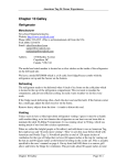
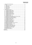
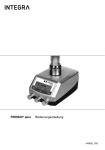
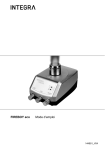
S-2A
Propane / CNG Fume Detector with Solenoid Valve Control
Installation and Operation Manual
MADE IN THE USA.
• Automatic Solenoid Control
• Dual Sensor Capability
• Microcomputer Operation
• Solid State Sensors
• Self Testing Circuitry
READ THIS MANUAL CAREFULLY AND
SAVE FOR FUTURE REFERENCE. KEEP
THIS MANUAL WITH THE S-2A.
Introduction
The S-2A vapor-monitoring system utilizes advanced technology for detection of propane (LPG)
fuel vapors as well as CNG (Compressed Natural Gas). The S-2A allows the connection of two
(2) sensors and has both visual and audible alarms. Test switches are provided for full checking
of all operations. System operation and correct sensor operation are continually monitored and
indicators are provided for fault detection. The S-2A has an internal relay for automatic control of
fuel solenoid. Read this owner’s manual completely before installation. Failure to read and follow
these instructions can result in damage to the unit voiding the warranty.
Components This Kit Includes
• One S-2A Display w/Bezel
• One SV-1 Solenoid Valve
• One 20 MS-2 Sensor
• Four screws for the display
• Two screws for the sensor
CAUTION: NO POWER ON/OFF SWITCH IS PROVIDED FOR THIS UNIT. TO
FUNCTION AS INTENDED, THE S-2A MUST BE CONNECTED TO A CORRECT
POWER SOURCE, AND FOR MAXIMUM EFFECTIVENESS, BE POWERED AT
ALL TIMES WHILE ABOARD. IF POWER IS ON AND LEFT UNATTENDED FOR AN
EXTENDED PERIOD OF TIME, BATTERY POWER MAY BE DIMINISHED.
P/N: 18122
Page 1
Rev Date: 9/7/07
Rev. 1.0
Tools Required and Hardware
• Screw Drivers (Slotted & Phillips)
• Electrical Connector Crimping Tool
With Wire Stripper
• Power Drill
• Electrical Tape
• Drill — 3/4 (19.05mm) Diameter
• Drill — 1/8” (3-17mm) Diameter
• Hole Saw 2-1/16” diameter
• Two 1 Ampere Fuse
• Wire Nuts (#16 Gauge Wire)
• A Length of #16 Gauge Wire
• Tape Measure and Pencil
• Crescent Wrench
• 2 in-Line fuse Holder -
Manual Display Controls / Indicator
A - Solenoid Valve Indicator
B - Sensor #1 Indicator
C - Sensor #2 Indicator
D - Unit Fault Indicator
E - Solenoid Valve On/Off Switch
F - Sensor #1 Test Switch
C - Sensor #2 Test Switch
H - Horn Mute Switch
I - Audible Horn (Internal)
Indicator Definitions
Solenoid Indicator
Green
Off
Sensor #1 & #2
Green
Amber
Red
Flashing Green
Off
Unit Fault
Off
Amber
= Solenoid Control on
= Solenoid Control off
= Sensor active, no fumes detected
= Sensor failure
= Fumes detected! alarm condition
= Sensor warm up period
= No sensor detected on power-up
Figure 1
= Unit Functional
= Fault Detected, horn beeping
Display Installation
The S-2A should be mounted in a convenient location, preferably at the source of propane usage
(i.e. galley, heater, etc…) where the visual indicators may be readily seen. To install the display,
you must first remove the snap-on bezel by inserting a small, flat blade screwdriver into the slot
located on either side of the bezel and carefully prying up until the bezel snaps free. (See figure 5)
CAUTION: Do not attempt to remove the four (4) screws, which are now exposed which attach
the printed circuit panel to the frame. Doing so will void all warranties.
Next, drill a 2-1 /16” diameter hole into the panel. Slip the instrument through the hole and
secure, making sure that you have access to the terminals for solenoid valve connections, positive
and negative terminal connections and sensor(s) connections.
Plug in your sensor to connector one and make positive and negative connections for the display
and solenoid valve. Finish the installation by fastening to panel with four screws (provided) and
snapping bezel back into place.
P/N: 18122
Page 2
Rev Date: 9/7/07
Rev. 1.0
Sensor Installation
The sensor supplied with the S-2A includes a
standard 20 foot ( 8.29m) cable. If a longer cable
is desired contact your dealer or Fireboy-Xintex.
Coil excessive cable in a convenient location.
Remove the paper covering the adhesive backing
on the sensor-mounting surface and press the
sensor into position on a previously cleaned
surface. Install with two (2) screws provided.
CAUTION: Do not attempt to use any other
manufacturer’s sensor or previously installed
sensors.
Figure 2
Sensor Location
CAUTION: Propane is heavier than air and will
settle. Therefore it is important that a location be
selected that is as low as practical and as near the
appliance as is possible. Keep sensor dry.
CNG (Compressed Natural Gas) is lighter than air and will rise. Therefore, it is important that a
location be selected that is within nine (9”) inches (22.86cm) of the ceiling height. Do not locate
sensor directly over cooking or heating appliances. Keep sensor dry.
Solenoid Installation
Propane (LPG) — Mount the solenoid in-line on the tank
side of the LPG regulator as close to the tank as is practical.
The tank itself should be mounted outside the cabin or
crew quarters to avoid the possibility of gas accumulation
due to a leak between the tank and the solenoid valve.
CNG — Because of the high tank pressure of CNG, the
solenoid valve MUST be installed after the CNG regulator
and as close to the regulator as practical. The tank
and regulator should be mounted outside the cabin or
crew quarters to avoid the possibility of gas accumulation
due to a leak between the tank and the solenoid valve,
NOTE: DO NOT over-tighten fittings. Doing so will cause
the solenoid valve to malfunction. After installation, check
all fittings for leaks with a soapy water solution - NEVER
use flame to check for leaks. Use 2 wrenches when tightening
connections to avoid twisting the valve and causing damage.
P/N: 18122
Page 3
Rev Date: 9/7/07
Figure 3
Rev. 1.0
Wiring the S-2A
Connect a length of 16-gauge wire from the control panel positive to the +12 VDC terminal on
the S-2A display through a 1-amp fuse. Connect a length of 16-gage wire from the control panel
buss bar ground to the negative terminal on the S2A display.
If you are supplying your own solenoid valve, disconnect solenoid valve from current system and
wire solenoid valve to S-2A display using figure 6 on page 4.
If you choose to use the valve provided in the carton, which is non-polarized, wire solenoid valve
to S-2A display using figure 6 on page 4.
Quick Disconnect Style Sensor with 20’ sensor cable is included. The disconnect/connector plug
is located 12” from the red sensor. In the event you need to replace the red sensor, simply
disconnect it at the plug and remove. When reattaching the sensor, make sure the connector
“snaps” into place by pushing the side locks in. This ensures a watertight seal. No need to reroute
or replace the 20’ sensor cable. NOTE: If longer sensor length is necessary, contact your retailer
or our factory for lengths 25’ through 100’.
Sensor Connection
Plug sensor #1 provided with the S-2A into the connector on the backside of display labeled #1. If
installing the optional second sensor, plug sensor #2 into the other connector.
Figure 5
P/N: 18122
Page 4
Rev Date: 9/7/07
Rev. 1.0
Overall Wiring Diagram
Figure 6
Terminal Strip Connections
- 12V = Display Ground (negative)
+ 12V = Display Positive
+V
= Solenoid Valve Positive
- V
= Solenoid Valve Ground (negative)
Operation
When first turning the unit on, the S-2A goes through an audio/visual cycle of all indicators and
the audible horn. Beginning with sensor #1, the indicators will cycle green, amber, and red. This
will then continue with sensor #2. If optional sensor #2 is not installed the indicator light will turn
off. The unit fault indicator will then illuminate, and then the horn will beep.
The sensor lights may flash green during the warm-up period. This flashing will occur only if a
sensor is connected. Warm-up time will vary depending upon usage of the unit. Long periods of
inactivity will require long warm-up periods. After the warm-up period, the indicator will change
to green. It a sensor is not installed the sensor indicator will turn off. The solenoid control may be
tested by pressing the solenoid switch. Pressing this switch again will turn the solenoid off.
CAUTION: Be certain solenoid switch is on! Gas will not flow through the system.
Should either of the sensors detect propane or CNG fumes, the corresponding indicator #1 or #2
will change to red and the audible horn will sound. The indicator will remain red as long as fumes
are detected. The solenoid control will turn off. Do NOT consider the area clear until the indicator
light returns to green.
Testing Display Mode
Internal operation of the display mode may be tested using the corresponding TEST switch.
Pressing the test buttons will simulate the above alarm conditions.
P/N: 18122
Page 5
Rev Date: 9/7/07
Rev. 1.0
Functional Testing of the Sensor
WARNING: DO NOT use a gasoline soaked rag or a container partially filled with gasoline to
test sensor. The raw gas could ignite resulting in serious injury. In addition, the isolated high
concentration of fumes may damage the sensor and render it inoperative.
To TEST SENSOR use butane lighter with the striker wheel removed. Hold the lighter to the
sensor and press down on the lever to release the Butane. In three to four seconds the warning
light will come on. In about ten seconds the alarm horn will sound. Remove lighter from the
sensor. Mute the alarm horn and within several seconds the warning light will shut off.
Whenever the S-2A alarms, the horn may be muted with the “MUTE” button, but THE
PROBLEM SHOULD NOT BE CONSIDERED CLEARED UNTIL THE ALARM LIGHT
GOES OUT
Sensor Fault Detection
Should the unit determine that either of the sensors is faulty or disconnected, the corresponding
indicator will change to amber and the horn will sound, Check that the sensor is connected and
that wiring has not been frayed or cut. Should this condition persist, the sensor has been damaged
and must be replaced.
Unit Fault Detection
Should an internal failure occur, the unit fault light will display amber and the horn will sound.
Should this occur, return the display to the manufacturer for repair.
Nuisance Alarms
The sensor used for the S-2A is sensitive to hydrocarbons- an alarm may be triggered by the use
of other chemicals such as cleaners, paint, polish, etc… The sensors will also detect hydrogen
fumes from an overcharged battery. If no gasoline fumes are present, check for recent use of
cleaners, fiberglass repairs, strong adhesives, etc… If none of these are present, the sensor may
have been damaged and will need replacement.
WARNING:
The S-2A has been designed to alarm nominally at 20% of the LEL (Lower Explosive Limit) of
Propane/CNG. Implement immediately the following procedures in the event of an alarm. Shut
down all appliances. Manually shut oft the source of Propane/CNG. Turn off all electrical circuits
EXCEPT circuits, which operate blowers and/or exhaust fans. Remove all personnel from the
area. Ventilate the area; turn on exhaust fans and open windows, hatches, etc… Carefully check
all fuel lines, tanks and fittings to locate the leak. Have the problem repaired by qualified
personnel.
Maintenance
The S-2A requires very little maintenance. Periodically examine the sensors for contamination or
damage. Check that sensor wires are not frayed, pinched, or cut. Test the operation of both
sensors and display frequently. Do NOT expose sensors to liquids or chemicals.
When cleaning, seal off the sensor(s) with a plastic covering. Harsh chemicals may damage the
sensor. Keep sensor(s) sealed until the compartment has been completely ventilated.
CAUTION: DO NOT FORGET TO REMOVE SENSOR COVERINGS OR THE S-2A WILL
NOT OPERATE CORRECTLY.
P/N: 18122
Page 6
Rev Date: 9/7/07
Rev. 1.0
Specifications
Voltage ………………………………………… +12VDC Nominal (10VDC min to
18VDC max)
Current ………………………………………… 150 mA per sensor / 300 mA max
(solenoid off)
Alarm ………………………………………… 20% Lower Explosive Limit (LEL)
Horn ………………………………………… 75dB @ 10cm 3kHz frequency
Solenoid Control ……………………………… 1 amp max
Solenoid Valve ………………………………… 312 PSI maximum
Current Draw (SV-1) ………………………… 800mA holding
Options
MS-2 Propane Sensor
SV-1 Solenoid Control Valve
CNV 12-1 12V Converter for 24/32 volt systems
All Options are available from Fireboy-Xintex. Contact the Customer Service Department at 866350-9500. Visa. Mastercard, or C.O.D accepted.
WARNING
The S-2A is a propane/CNG (Compressed Natural Gas) detector ONLY. This device is
meant to serve as a supplement warning only. It is NOT intended to replace standard
safety practices which should be carried out around explosive gases (i.e. inspect all
rooms and compartments, check all gas fittings and connections, smell for
propane/CNG gas fumes, etc…) To function properly the S-2A must be powered at all
times while aboard. Do not install this outdoors. Before installing in applications which
may appear different than those outlined in this manual, contact Fireboy-Xintex 866350-9500. This device is not intended for use in aircraft.
There are no user or field serviceable parts in this product. The S-2A must be returned
to the manufacturer for any repair or trouble shooting beyond what is recommended in
this manual. Installation shall be done by qualified personnel authorized to do so by the
authorities having jurisdiction for the particular application in which the product is
being used. Electrical wiring shall be in accordance with applicable codes. Improper
wiring, including all wire connections, may render the unit inoperable, damage
components, or cause a fire, and will void all warranties
More Safety Products from FIREBOY/XINTEX
• Clean Agent Automatic Fire Extinguishers
• Clean Agent Manual / Automatic Fire Extinguishers
• M-1 / M-2A Gasoline Fume Detectors
• MB-1 / MB-2 Gasoline Fume Detectors with Blower Control
• CMD-4M Carbon Monoxide Detectors
P/N: 18122
Page 7
Rev Date: 9/7/07
Rev. 1.0
One (1) Year Limited Warranty
This Warranty is in lieu of all other express or implied warranties.
Seller warrants title, materials, and workmanship on Fireboy equipment and assigns,
the original manufacturer’s warranty on those components manufactured by others,
as permitted. Seller’s warranty shall be for a period of (1) one year from the date of
sale to the ORIGINAL CONSUMER Fireboy-Xintex, Inc. does not assume the
costs of removal and/or installation of the product or any other incidental costs
which may arise as a result of any defect in materials or workmanship. Any nonconforming equipment returned to the Seller at Buyer’s expense and risk shall be
repaired or replaced at Seller’s option, provided that: (a) the product has not been
subjected to abuse, contamination, neglect, accident, incorrect wiring not our own,
improper installation or servicing, or used in violation of the instructions furnished
by Fireboy-Xintex, Inc. (b) the product has not been repaired or altered by anyone
other than Fireboy-Xintex, Inc. (c) the serial number has not been removed,
defaced, or otherwise changed (d) the product is determined to contain defective
materials or workmanship: and (e) use of the product is discontinued upon
discovery of detective materials or workmanship and Fireboy-Xintex Inc. is notified
immediately.
ANY WARRANTY IMPLIED BY LAW, INCLUDING WARRANTIES OF
MERCHANTABILITY OF FITNESS, IS IN EFFECT ONLY FOR THE
DURATION OF THE EXPRESS WARRANTIES, OR TO ASSUME FOR
FIREBOY/XINTEX, INC., ANY OTHER LIABILITY IN CONNECTION WITH
THE SALE OF ITS PRODUCTS. FIREBOY/XINTEX, INC. SHALL BE NOT
LIABLE FOR THE LOSS OF USE, REVENUE, PROFIT, INJURY OR ANY
OTHER CONSEQUENTIAL OR INCIDENTAL DAMAGES. BUYER IS NOT
RELYING ON SELLER’S JUDGEMENT REGARDING BUYERS
PARTICULAR REQUIREMENTS, AND HAS HAD AN OPPORTUNITY TO
INSPECT THE PRODUCT TO BUYER’S SATISFACTION.
FIREBOY-XINTEX, Inc.
Mailing Address: PO Box 152, Grand Rapids, MI USA 49501-0152
Shipping Address: O-379 Lake Michigan Drive NW, Grand Rapids, MI USA 49534
Phone (616) 735-9380
Fax (616) 735-9381
Website: www.fireboy-xintex.com
Email: [email protected]
TOLL FREE: 1-866-350-9500
P/N: 18122
Page 8
Rev Date: 9/7/07
Rev. 1.0
P/N: 18122
Page 9
Rev Date: 9/7/07
Rev. 1.0