1
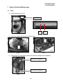
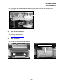
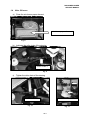
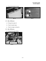
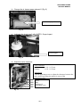
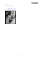
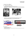
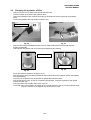
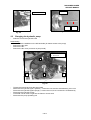
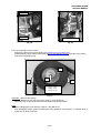
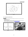
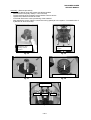
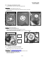
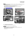
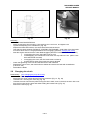
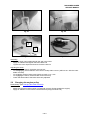
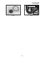
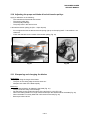
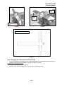
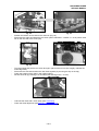
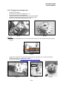
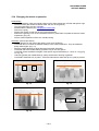
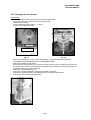
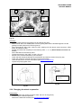
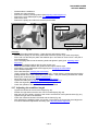
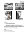
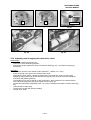
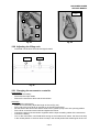
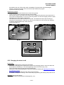
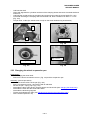
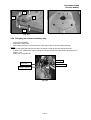
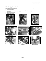
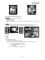
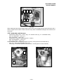
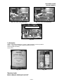
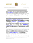
RANSOMES SPIDER
SERVICE MANUAL
1
Spider Routine Maintenance ................................................................2
1.1
1.2
1.3
1.4
1.5
1.6
1.7
2
Daily:.......................................................................................................... 2
After the first 8 hours: ................................................................................ 3
After 25 hours: ........................................................................................... 3
After 50 hours: ........................................................................................... 4
After 100 hours: ......................................................................................... 5
After 200 hours: ......................................................................................... 5
Seasonally: ................................................................................................ 7
Spider Service Manual .........................................................................8
2.1
2.2
2.3
2.4
2.5
2.6
2.7
2.8
2.9
2.10
2.11
2.12
2.13
2.14
2.15
2.16
2.17
2.18
2.19
2.20
2.21
2.22
2.23
2.24
2.25
2.26
2.27
2.28
Changing the engine oil filter ..................................................................... 8
Changing the hydraulic oil filter ................................................................. 9
Changing the hydraulic pump.................................................................. 10
Changing the hydraulic drive ................................................................... 12
Changing the blade drive belt.................................................................. 14
Changing the blade hub bracket.............................................................. 14
Changing the pump drive belt.................................................................. 15
Changing the clutch................................................................................. 16
Changing the engine pulley ..................................................................... 17
Adjusting the pump and blade drive belt tension pulleys......................... 19
Sharpening and changing the blades ...................................................... 19
Changing the roller chain of the steering................................................. 20
Changing the steering motor ................................................................... 22
Changing the wheel suspension.............................................................. 23
Changing the travel belts......................................................................... 24
Changing the wheel suspension.............................................................. 25
Adjusting the stabiliser length.................................................................. 26
Adjusting the wheel alignment................................................................. 27
Adjusting and changing the wheel drive chain ........................................ 28
Adjusting the lifting rods .......................................................................... 29
Changing the servomotor controller ........................................................ 29
Changing the wheel shaft ........................................................................ 30
Changing the wheel suspension pan....................................................... 31
Changing the starter switching relay ....................................................... 32
Changing the main cable harness ........................................................... 33
Changing the DC electric motor .............................................................. 34
Replacing the fuses ................................................................................. 34
Carburettor maintenance......................................................................... 35
Lubricants .................................................................................................36
Service tools .............................................................................................36
GB-1
RANSOMES SPIDER
SERVICE MANUAL
1 Spider Routine Maintenance
1.1
Daily:
a) Check the engine oil level
Limit mark
Min
Max
Fig. 1
b) Clean the engine and pump air cooling intake
Fig. 3
Fig. 2
c)
Check that the cutter blade is secure and check its sharpness and balance
Check screw tightness
Check blade sharpness
Fig. 4
GB-2
RANSOMES SPIDER
SERVICE MANUAL
d) Lubricate the toothed segment and the guide bush of the cross welded piece
(XINTEX – Slix)
Fig. 5
1.2
After the first 8 hours:
a) Change the engine oil
- see Changing the engine oil filter
1.3
After 25 hours:
a) Clean the air cleaner foam element
Air cleaner foam element
Fig. 7
Fig. 6
GB-3
RANSOMES SPIDER
SERVICE MANUAL
1.4
After 50 hours:
a) Clean the air cleaner paper element
Air cleaner paper element
Fig. 8
b) Lubricate the roller chain of the steering
CHAIN SPRAY
Fig. 9
c)
Tighten the roller chain of the steering
Tension ± 20 mm
Screws of chain tensioner
Fig. 10
Fig. 11
GB-4
RANSOMES SPIDER
SERVICE MANUAL
d) Check the hydraulic oil level
Fig. 12
1.5
Fig. 13
After 100 hours:
a) Change the engine oil
b) Clean the spark plugs
c)
1.6
Clean the engine cooling fins
After 200 hours:
a) Change the engine oil filter
Engine oil filter
Fig. 14
GB-5
RANSOMES SPIDER
SERVICE MANUAL
b) Change the air cleaner paper element 2 (Fig. 8)
Air cleaner paper element
Fig. 15
c)
Lubricate the wheel rims 2 with XINTEX - Super Impact
Grease nipple
Fig. 16
d) Adjust the valve clearance
Valve clearance
Intake
- 0.10 – 0.15 mm
Exhaust
- 0.10 – 0.15 mm
Adjustment:
Turn the adjusting screw to adjust the clearance between the
valve and beam (when the piston is at top of the
compression lift)
Valve
Rod
Lifting rod
Adjusting screw
Fig. 17
GB-6
RANSOMES SPIDER
SERVICE MANUAL
1.7
Seasonally:
a) Change the hydraulic oil
See changing the hydraulic oil filter
b) Change the fuel filter
GB-7
RANSOMES SPIDER
SERVICE MANUAL
2 Spider Service Manual
2.1
-
Changing the engine oil filter
Thoroughly clean the area around the oil filter and the filler neck
Drain the oil from the crankcase through the filler neck (or with the drain bolt when the machine is
tilted) CAUTION! The oil must not run under the engine (or into the clutch area to prevent the belts
from slipping)
Oil extractor
Filler neck
Fig. 18
Fig. 19
-
Disassemble and change the oil filter (lubricate the filter seal with oil during assembly)
Top up the engine oil with roughly 1.5 l (1.7 l when changing the oil filter)
Check the oil level with the dipstick (fill to the upper limit for better slope access)
Recommended Oil Viscosity Grades
-25°C
-20°C -15°C
-10°C -5°C
-0°C
5°C
10°C
15°C
20°C
25°C
30°C
35°C
40°C
SAE 10W
SAE 30W
SAE 40W
SAE 15W / 40
SAE 5W / 30
SAE 10W / 40
Fig. 21
SAE 80W
SAE 90W
Min
Max
Fig. 20
Recommended oils:
- SF, SG, SH, SJ, API Classification
- Oil viscosity (see Table 1)
- Multigrade oils (5W-20, 10W-30, 10W-40) increase oil consumption. When these are used, check
the oil level more frequently.
GB-8
RANSOMES SPIDER
SERVICE MANUAL
2.2
-
Changing the hydraulic oil filter
Drain the oil from the hydraulic tank through the filler neck
Tilt the machine on the side of the hydraulic tank
Clean the underside of the machine thoroughly (CAUTION! Dirt must not get into the hydraulic
tank!)
Loosen the hydraulic filter cap (spanner size 63 mm)
Oil filter cap
Fig. 22
-
Fig. 23
Remove and change the MANN FILTER H 601/4 (CAUTION! Ensure that the seal rings are
properly positioned!)
Lubricate the rings lightly with oil to ensure good tightening and sealing
Rubber ring
Sealing ring
Fig. 25
Fig. 24
-
Fill up with OHM 32 hydraulic oil (approx. 6.5 l)
Start the engine and by travelling backwards and forwards bleed the hydraulic system (the wheels
must rotate freely)
Top up the oil so that the level is between the gauge Min and Max marks
Run the machine to warm up the oil to operating temperature; check the tightness of the oil filter
cap and the tank cap
If the expansion tank overfills, drain some of the oil
CAUTION! When the hydraulic oil warms up the oil level rises up to the neck of the hydraulic tank!
Top up to the line on the dipstick only when the oil is cold!
GB-9
RANSOMES SPIDER
SERVICE MANUAL
Dipstick
Expansion tank
Max
Fig. 27
Fig. 26
2.3
-
Min
Changing the hydraulic pump
Drain the oil from the hydraulic tank
Disassembly:
- Disassemble the stabiliser on the left-hand side (for better access to the pump)
- Remove the fan grille
- Remove the fan
- Remove the fan cover (3 screws on pump head)
1 – Grille screws
2 – Fan screw
1
1
2
1
Fig. 28
-
Tighten the screws back into the pump head
Disconnect the hydraulic pipe A (shorter) – loosen the nuts 2 and 3 simultaneously, then nut 4
Disconnect the hydraulic pipe B (longer) – loosen the nut 5, then nuts 6 and 7 simultaneously
Disconnect the hydraulic hoses
CAUTION! The oil must not get into the frame or clutch area!
Disconnect the pump operating rod
GB-10
RANSOMES SPIDER
SERVICE MANUAL
Pipe B
Pipe A
Hydraulic hoses
Fig. 29
Fig. 30
From the underside of the machine:
- Remove the belt from the pump pulley (see changing the pump drive belt)
- Disassemble the pump pulley (CAUTION! Remove the retaining bolt from the side of the pulley!)
- Remove the hydraulic pump
1
2
3
3
1 – Safety screw
2 – Pulley screw
3 – Pump screws
Fig. 31
Assembly: (Reverse procedure)
- Use an adhesive on the bolt to the pump shaft (i.e. LOCTITE 243)
- Seal the pump contact surface and the bolt heads with silicone sealant
Note
- When changing the pump add 0.5 l (approx.) of hydraulic oil
- After starting the engine, gently increase the running speed (air in the system – increased noise of
hydraulics for about a minute)
GB-11
RANSOMES SPIDER
SERVICE MANUAL
Fig. 32
2.4
Changing the hydraulic drive
Disassembly:
- Disconnect the hydraulic drive hose (CAUTION! Do not allow the oil to to come into contact with
the V-belts!)
- Remove the expansion tank
- Remove the control unit
- Disconnect the controls bracket from the support and disconnect the DC electric motor (Fig. 34)
- Remove the support and cross welded piece (see changing the travel belts)
- Remove the pulley and hydraulic drive from the cross welded piece (Fig. 32)
Fig. 34
Fig. 33
GB-12
RANSOMES SPIDER
SERVICE MANUAL
Assembly: (Reverse procedure)
- Seal the hydraulic drive and screws with silicone sealant
- Seal the bolt in the pulley shaft (i.e. LOCTITE 243)
- Tighten the bolts of the hydraulic drive pressure hoses to 95 Nm
- Tighten the overflow hose bolt to 50 Nm
- CAUTION! Ensure the correct positioning of the washers!
- After starting the engine, lightly increase the running speed (air in the system – increased noise of
hydraulics for about a minute)
Hydraulic drive
sealing contact
surface
Hydraulic drive
screws
Fig. 35
Fig. 36
Spring
Use an adhesive on the pulley
Fig. 37
Fig. 38
Torque values
95Nm
50Nm
Fig. 39
GB-13
95Nm
RANSOMES SPIDER
SERVICE MANUAL
2.5
-
Changing the blade drive belt
Lift the machine or tilt it on the side of the hydraulic tank
Disassembly:
- Remove the cutter blade and clutch cover
- Loosen the nut securing the spring and release the tension on the belts
- Pull off the belt
Cutter blade screws
Clutch cover screws
Fig. 40
Fig. 41
Fig. 42
Assembly: (Reverse procedure)
- Replace the B 750 GOODYEAR belt
- Adjust the clearance between the spring and the locknut
- Use an adhesive on the clutch cover bolts
- Seal the cover with sealant to prevent the infiltration of dirt and dampness
Spring safety nut
Blade
drive belt
Pump
drive belt
Fig. 44
Fig. 43
2.6
-
Changing the blade hub bracket
lift the machine or tilt it on the side of the hydraulic
Disassembly: (see changing the blade drive belt)
- Disassemble the blade hub bracket including the tension levers
- Remove the tension levers and pulley
- Remove the bolt securing the blade hub
- Remove the blade hub
GB-14
RANSOMES SPIDER
SERVICE MANUAL
Assembly:
- When changing the bearings of the blade hub, apply an adhesive on the bearings (LOCTITE 638)
- Push the blade hub back on
- Clean the pulley pins, lubricate them and use threadlock on the threads (LOCTITE 243)
- Check that the belt is in the centre of the tension pulley (Fig. 46)
- Check that the tension levers and pulleys rotate freely
- Apply an adhesive on the central screw securing the cutter pulley (LOCTITE 243)
- Tighten the screws of the bracket to 70 Nm
- see also changing the blade drive belt
Tension lever pins
Belt in centre of tension pulley
Blade hub screw
Fig. 45
Fig. 46
Long tension lever
Fig. 47
Short tension lever
Fig. 48
2.7
-
Changing the pump drive belt
Lift the machine or tilt it on the side of the hydraulic tank
Disassembly:
- Remove the cutter blade, clutch cover and blade hub bracket
- Measure the distance (x) of the clutch brake disk (Fig. 49) and note it (approx. 28 mm)
- Loosen the adjusting nut 1 and retaining nut 2
- Remove clip 3, slide off spring 4 and nut 2
- Change the belt
GB-15
RANSOMES SPIDER
SERVICE MANUAL
Fig. 50
Fig. 49
Assembly:
- Fit the B 1060 GOODYEAR belt
- Gently screw bolt 3 through spring 4 into retaining nut 2 and nut 5, and tighten nut 2
- Tighten the adjusting nut 1 to distance x (Fig. 49)
- Replace the blade hub bracket, the cutter belt and the belt tensioners
- Test that the clutch engages (WITHOUT STARTING THE ENGINE) – both sides of the disc brake
must have about 0.5 to 1 mm gap between them on engaging (see also changing the clutch)
- Start the engine and test that the cutter blade engages (WITHOUT ASSEMBLING THE BLADE)
• on engaging the clutch, the brake must not lock
• on disengaging, the mechanism must come to a stop within 0.5 sec. (within 5 sec.
with cutter blade mounted)
• on engaging the clutch, the disc brake must not heat up
• check that both sides of the brake are evenly adjusted
- Check the tightening of the nuts and the belt tension and clearance
- Replace the clutch cover, seal it with silicone sealant and secure the bolts with threadlocker
(LOCTITE 243)
- Assemble the blade
2.8
Changing the clutch
Disassembly: (see changing the pump drive belt)
- Disconnect the battery
- Disconnect the clutch cables and the FASTON connector (Fig. 51, Fig. 52)
- Unscrew bolt 1 securing the clutch clip (Fig. 53)
- Unscrew the main clutch bolt 2 (while turning the clutch shaft, screw in the bolt, secure it with a nut
from the front side of the clutch and whilst holding this loosen bolt 2) (Fig. 54)
- Remove the clutch (Fig. 54)
GB-16
RANSOMES SPIDER
SERVICE MANUAL
Fig. 51
Fig. 52
2
1
Fig. 53
Fig. 54
Assembly:
- Push the clutch input cables through the gap in the frame
- Apply an adhesive and tighten the main clutch bolt
- Tighten the clutch clip bolt and secure it with the locknut
Adjusting the clutch:
- On engaging the clutch, the brake must not lock
- On disengaging, the mechanism must come to a stop within 0.5 sec. (within 5 sec. with the cutter
blade mounted)
- On engaging, the disc brake must close by around 0.5 to 1 mm
- On engaging the clutch, the disc brake must not heat up
- Check that both sides of the brake are evenly adjusted
2.9
Changing the engine pulley
Disassembly: (see changing the blade drive belt)
CAUTION!
- Make sure that the locking washer is positioned correctly (facing towards the engine)
- Apply an adhesive on the central countersunk bolt (using LOCTITE 243)
GB-17
RANSOMES SPIDER
SERVICE MANUAL
Adhesive on screw
Pump belt
Fig. 56
Fig. 55
GB-18
RANSOMES SPIDER
SERVICE MANUAL
2.10 Adjusting the pump and blade drive belt tension pulleys
Apply an adhesive on the following:
- The central bolt of the blade hub bracket
- The tension pulley bolt
- The belt pulley bearings
- The pulley bolts in the tension lever
Lubricate the tension pulley pin (Slix – Super Impact)
-
Do not tighten the locknut that secures the spring right up to the spring itself – Leave about 1 mm
clearance
Check that the belt is in the centre of the tension pulley (Fig. 57)
Fig. 58
Fig. 57
2.11 Sharpening and changing the blades
Sharpening:
- Sharpen along the length of the blade
- The pitch of the cutting edge should be about 40°
- Sharpen both sides of the blade equally
Balancing:
- Use the special device for balancing the blade (Fig. 61)
- The pin must turn freely in the bearing!!!
- Set the blade on the cylindrical surface of the tool held in a vice (Fig. 60)
- When the rotating blade is no longer horizontal sharpen the heavier side of the blade (Fig. 59)
- When the blade is correctly balanced it will remain horizontal (Fig. 60)
- Bolt torque value: 60 Nm
GB-19
RANSOMES SPIDER
SERVICE MANUAL
Sharp
edge
Sharp
edge
Sharpen more
here
Fig. 60
Fig. 59
Cutter blade balancing tool
Fig. 61
2.12 Changing the roller chain of the steering
-
It may be necessary to change the chain if it is slacked and cannot be tightened any more (when
slacking is first noticed it is possible to shorten the chain by one link)
Procedure for changing the chain:
- Lift the machine (wheels off the ground)
- Move the chain round so that the clip is on the side of the steering motor
GB-20
RANSOMES SPIDER
SERVICE MANUAL
Fig. 62
-
Fig. 63
Slacken the tension of the chain to the minimum (Fig. 64)
Disconnect the chain and attach the new chain (roller chain 084-1 * MOFA ½” x 3/16”) with a chain
link on the free end of the chain (left)
Fig. 64
-
Fig. 65
Turn the wheels and pull the new chain through in place of the old one (this roughly maintain the
wheel alignment)
Disconnect the old chain and link the new chain together (by securing the clip on the top)
Check the position of the chain in the guiding pulleys
Secure the chain (by drawing it on the side of the steering motor ± 20 mm)
Fig. 66
-
Lubricate the chain with a chain spray (see Lubricants)
Check the wheel alignment (see adjusting wheel alignment)
GB-21
RANSOMES SPIDER
SERVICE MANUAL
2.13 Changing the steering motor
-
Disconnect the battery
Disconnect the motor input cables (Fig. 67)
Loosen the roller chain of the steering
Disconnect the chain and release it from the motor cogwheel
Detach the clamping sleeve from the motor shaft (Fig. 68)
Slacken the motor bolts and replace the motor
Fig. 67
Fig. 68
Assembly:
- Assemble the clamping sleeve on the shaft so that the chain is in the centre of the tension pulley
(Fig. 69)
Fig. 69
-
Tighten the countersunk screws of the clamping sleeve alternately, up to 10 Nm (CAUTION!
Ensure that the spring is positioned correctly)
Tighten the chain (see Changing the roller chain of the steering )
Spring
Fig. 70
Fig. 71
GB-22
Fig. 72
RANSOMES SPIDER
SERVICE MANUAL
2.14 Changing the wheel suspension
Disassembly:
- Before disassembly mark the original position of the wheel suspension, bracket and spacer rings
- Lift the machine (the wheels must be at least 150 mm off the ground)
- Turn the suspension so that it is straight
- Disassemble the bracket (see changing the travel belts)
- Remove the pulley
- Support the wheels so that they do not become detached
- Remove the gearing cover on the underside of the arm (CAUTION! This plate secures the wheel
suspension) (Fig. 76)
- Pull the wheel suspension off the arm needle bearing
Assembly: (reverse procedure)
- Use an adhesive on the bolts of the gearing cover (LOCTITE 243)
- CAUTION! Do not confuse the different settings of the wheel suspension. They have different
pulley shaft lengths. (Fig. 73)
- Keep the wheels aligned (or adjust their alignment after assembly)
- CAUTION! Place the needle bearing protective ring on the arm groove
- CAUTION! Check the different lengths of the spacer rings and brackets (A – short, B – long) (Fig.
74, Fig. 75)
- Lubricate (grease) the needle bearings, pulley shaft and the steering cogwheels
- CAUTION!!! Assemble only by hand – clean and lubricate the shaft and slip it in gently by hand!!!
A
B
Fig. 73
Fig. 74
4 screws
Fig. 75
Fig. 76
GB-23
RANSOMES SPIDER
SERVICE MANUAL
2.15 Changing the travel belts
Disassembly:
- Lower the setting of the machine to the minimum cutting height
- Lift the machine (the wheels must not touch the ground)
- Disconnect the battery
- Loosen the pump bypass valve (1 – 2 turns)
- Loosen the belt tension pulleys
By-pass valve
Fig. 77
-
Fig. 78
After unscrewing bolts 1, 2 and 3 of the bracket (Fig. 81), pull the bracket off the shaft
(CAUTION!!! The brackets must not be mixed! MARK THEM)
Remove the belts from the pulleys
Disconnect the STOP button, the connector of the DC electric motor, the steering unit, the horn,
the antenna, the choke rod, the hydraulic oil overflow hose and the lift rods (of the pinions); the
hydraulic hoses may remain connected!
Remove the stop springs (Fig. 79)
Remove the screws holding the support and release the support
Remove the support and the cross welded piece by turning the lifting levers
Change the SPA 1650 GOODYEAR belts
Fig. 79
GB-24
RANSOMES SPIDER
SERVICE MANUAL
3
4
Carrier
screws
Carrier
screws
Lifting lever
2
1
Fig. 80
Assembly:
- Place the belts between the guiding bars and the lift stop clips
- Fit the carrier and cross welded piece onto the guiding bars and the toothed segment onto the
guiding bar teeth (first tooth in the first groove)
- Fit the stop springs, lifting rods, choke rod, horn, steering unit, DC electric motor connector, STOP
button and antenna cable
- Position the belts onto the pulleys in the following order: 1, 2, 3, 4 (Error! Reference source not
found.)
- Fit the bracket onto the shaft by hand
- Tighten the screws in the order 3, 2 and 1 (Fig. 81)
- Secure screw 2 with an adhesive (LOCTITE 243)
- Check that the clearance between the transmission and the bar is about 4mm (Fig. 82)
- Check the clearance of the lift rods (they must all pull equally)
- Lubricate the pinions and the cross sleeve (see Spider maintenance)
- Tighten the pump bypass valve
Clearance: 4 mm
(approx.)
Fig. 82
Fig. 81
2.16 Changing the wheel suspension
Disassembly:
- Lift the machine (the wheels must be at least 150 mm off the ground)
- Disassemble the wheel suspension
- Remove the belts and brackets (see changing the travel belts)
GB-25
RANSOMES SPIDER
SERVICE MANUAL
-
Disassemble the stabilisers
Slacken the chain tensioner
Remove the steering clamping sleeve (see adjusting wheel alignment )
Remove the cross welded piece (see changing the travel belts)
Slide off the arms
Remove the pulleys and rods from the ball joint brackets
Lubricant
Xintex – Super Impact
Fig. 84
Fig. 83
Assembly:
- Grease the guide sheaths (Xintex – Super Impact) and insert the arms
- Assemble the pulleys on the arms (CAUTION! Check the spacer rings under the pulleys)
- Fit the rod onto the ball joint (warm the stabiliser pin in hot water for around 5 min. and push it
onto the ball joint)
- Fit the clamping sleeve onto the steering shaft and tighten it gently (see adjusting wheel
alignment )
- Assemble the spring together with the nylon spacer ring
- Place the travel belts between the guide bars and clips of the lift stops
- Assemble the cross welded piece and support (see changing the travel belts)
- Fit the wheel suspension
- Fit the brackets (see changing the travel belts)
- Using a grease gun, lubricate the arms (with Xintex – Super Impact), toothed segment and the
guiding sheath of the cross welded piece (with Xintex – Slix), the steering transmission needle
bearing with a lubricant (see Spider maintenance)
- Adjust the length of the rods (see adjusting stabiliser length)
- Tighten the chain (see Changing the roller chain of the steering )
- Check the alignment (see adjusting wheel alignment )
- Check the operation, lift and rotation of the machine wheels
2.17 Adjusting the stabiliser length
-
Tighten the left side to the minimum length (Fig. 85)
Slacken the right side so that the arm can be turned slightly (Fig. 86)
Align the axis of the pulley, the axis of the column and the axis of the hydraulic drive (Fig. 87)
Tighten the right side of the stabiliser
Check the clearance between the wheel and the frame (Fig. 88)
After adjusting the stabiliser length, the tension of the steering chain and the wheel alignment
must be checked and adjusted if necessary (see adjusting wheel alignment )
GB-26
RANSOMES SPIDER
SERVICE MANUAL
Fig. 85
Fig. 86
Fig. 87
Fig. 88
2.18 Adjusting the wheel alignment
-
-
Lift the machine (the wheels must be off the ground)
Align the wheels
Slacken the clamping sleeve of the steering chain
• Unscrew the countersunk screws 1 (Fig. 89)
• Tighten one screw into the thread to release the clamping sleeve 2 (Fig. 90)
• The clamping sleeve is released as the screw is tightened
• Return the countersunk screws to thread 1 (screw them in but do not tighten them – it
must be possible to turn the wheel by hand)
CAUTION! When turning do not let the screws come into contact with the travelling pulley (Fig. 91)
Adjust the wheels so that they are parallel. Place a straight board against the portal of the wheels
on the left and the disc of the tyre on the right (Fig. 92, Fig. 93)
Tighten at least one of the (accessible) clamping sleeve screws – the wheels must not be turned
before at least one screw is tightened, since this would misalign the wheels!
After tightening the first screw turn the wheels slightly (CAUTION! The wheels must be off the
ground!)
Tighten the second screw
Check their alignment with the board
Alternately turn the wheels and tighten both of the clamping sleeve screws on each wheel until the
clamping sleeve is completely tight (23 Nm approx.)
GB-27
RANSOMES SPIDER
SERVICE MANUAL
1
2
Fig. 89
CAUTION!
Fig. 90
Fig. 92
Fig. 91
Fig. 93
2.19 Adjusting and changing the wheel drive chain
Disassembly:
- Remove the wheel suspension cap
- Remove the chain tensioning segment
- Remove the small cogwheel from the transmission shaft (Fig. 94) – CAUTION! The spring is
tensioned!!!
Assembly:
- Fit the chain onto the chain wheels (roller chain 084-1 * MOFA 1/2“ x 3/16“)
- Place the spring in the groove of the transmission shaft
- Assemble the chain wheel – tighten the wheel with a screw (longer, around 30 mm); after
tightening change this longer screw and take the original screw, and secure it with threadlock
(LOCTITE 243) before tightening
CAUTION!!! Do not use a hammer on the small wheel – allow clearance in the transmission!!!
- Fit the tensioning segment and gently tighten screws 2 (Fig. 94)
- Tighten the chain with the adjusting screw 1 (± 5 mm) CAUTION! The rotation must be free!!! (Fig.
95)
- Lubricate with a chain spray
- Tighten the cap (seal with silicone sealant)
- Torque value: 9 Nm
GB-28
RANSOMES SPIDER
SERVICE MANUAL
± 5 mm
1
2
2
Fig. 94
Fig. 95
2.20 Adjusting the lifting rods
-
CAUTION! The locknuts have left and right threads!
Right
Left
Fig. 96
2.21 Changing the servomotor controller
Disassembly:
- Disconnect the battery
- Disconnect the input cables
- Remove the servomotor lever and the servomotor
Assembly:
- Assemble the servomotor
- Check and if necessary adjust the length of the rod (Fig. 99)
- Fit the rod to the pump lever pin and the pin of the servomotor lever
- Set the shaft of the servomotor and the shaft of the hydraulic pump to the zero (centre) position
- Fit the lever on the servomotor shaft and tighten the locknut
- Connect the wires of the servomotor regulator and the input controlling cables of the servomotor
- Connect the battery
- Turn on the main switch. CAUTION! After turning on the machine main switch, the lever must stop
in the central position. If the lever does not stop in the central position but instead goes as far over
GB-29
RANSOMES SPIDER
SERVICE MANUAL
-
as possible, then turn off the main switch immediately! The servomotor may be damaged
seriously. Change the polarity of the servomotor input cables and try again.
Tighten the lever nut (30 Nm)
Adjustment of neutral:
- Support the machine (the wheels must not touch the ground)
- Loosen the servomotor rod locknut (left and right threads)
- Start up the machine. CAUTION! The machine can be started only when the servomotor lever is
on the zero (central) position. If it is not on the zero position, turn the lever slightly until the neutral
LED lights up on the machine control panel
- Test the travel on both sides and leave it in neutral. The wheels must stop upon returning to
neutral from both directions. If they do not, then turn the central nut of the servomotor adjusting
rod slowly until the wheels stop in both directions.
- Tighten the safety nut
Fig. 97
Fig. 98
R
L
153 mm
Fig. 99
2.22 Changing the wheel shaft
Disassembly:
- Remove the wheel (three screws fixing the wheel)
- Remove the clamping sleeve (slacken the screws of the clamping sleeve 1 and screw them into
the threads for slackening 2 – with even tightening remove the sleeve) (Fig. 100)
- Clean the wheel shaft (must pass through the bearings)
- Remove the cap, tensioning segment, chain and small chain wheel (see adjusting and changing
the wheel drive chain)
- Remove the wheel shaft with the chain disk from the bearings
- If necessary change the bearings, remove the safety ring securing the bearings and pull them off
Assembly: (reverse procedure)
- Check the spacer ring between the bearings (Fig. 101)
GB-30
RANSOMES SPIDER
SERVICE MANUAL
-
Lubricate the shaft
Clean and degrease the cylindrical surfaces of the clamping sleeve that touch the wheel shaft and
wheel hub
Lubricate the conical surface of the sleeve and screws (even under the screw head) (Fig. 102)
CAUTION! On fitting the clamping sleeve and wheel hub, allow a clearance of about 1 – 2 mm
(Fig. 103)
Torque value: 10 Nm (the wheels must not slip on the wheel shafts during acceleration)
1
2
Closing sleeve
Fig. 100
Fig. 102
Gap 1-2 mm
Securing bearings
Fig. 101
Fig. 103
2.23 Changing the wheel suspension pan
Disassembly:
- See changing the wheel shaft
- Remove the fourth countersunk screw 1 (Fig. 104) and the suspension pan
Assembly: (reverse procedure)
- Clean the contact surface of the pan (Fig. 105)
- Fit the countersunk screws 1 and secure with an adhesive
- Secure the pan – spring clip 2 (Fig. 104)
- Assemble the large chain wheel, clamping sleeve and wheel hub (see changing the wheel axle)
- Assemble the chain and the small chain wheel
- Assemble the tensioning segment
- Tighten and lubricate the chain (see adjusting and changing the wheel drive chain)
- Fit the wheel suspension cap
GB-31
RANSOMES SPIDER
SERVICE MANUAL
1
2
2
1
Fig. 105
Fig. 104
2.24 Changing the starter switching relay
- Disconnect the battery
- Remove the relay wires
- When fitting the relay, pin the earth wire of the relay under the screw holding the relay
Check:
- When energising the relay there must be a voltage on both of the relay power terminals
- If there is not, measure the control voltage on the input (brown) terminal. When energising the U
starter = 12V
- Relay 12V / LG35 IN LBS
Frame
Input cable
Control cable
Starter conductor
Fig. 106
GB-32
RANSOMES SPIDER
SERVICE MANUAL
2.25 Changing the main cable harness
Note: The cable harness of the Kohler and Kawasaki motors varies in lengths according to the input wires
of the individual pieces of equipment.
Disconnect the battery
Disconnect the junction box from all equipment: the steering unit, fuel control, carburettor solenoid, DC
electric motor, STOP button, horn, charging, clutch, travel servomotor, steering motor, starter relay and
control panel
Unscrew the fuse box lid
- Remove the fuse box
Starter relay (Kawasaki)
Control panel
Battery earth
Charging (Kawasaki)
Carburettor solenoid
Connector
Steering electric motor
Fuse box
Starter (Kohler)
GB-33
RANSOMES SPIDER
SERVICE MANUAL
Charging (Kohler)
Starter relay (Kohler)
2.26 Changing the DC electric motor
Disassembly:
- Set the machine to the minimum cutting height
- Disconnect the battery
- Loosen the input cables
- Remove the DC electric motor and replace it (CAUTION! Ensure that the motor is facing the right
way!)
Assembly:
- CAUTION! Check the colour code of the input cables and their position within the connector!!!
(The motor may be damaged seriously when the connection is wrong!!!) (Fig. 107)
H
M
B
C
H
M
B
C
Fig. 107
H – Brown
M – Blue
B – White
C – Red
Fig. 108
2.27 Replacing the fuses
-
The fuse box is located beside the accumulator
The diagram shows the individual systems and the position of the fuses inside the fuse box
1.
2.
3.
4.
5.
10 A – Control panel, carburettor solenoid
15 A – Steering unit, travel control, machine lift
20 A - Steering servomotor
30 A – Main fuse
20 A – Charge of accumulator, blade clutch
GB-34
RANSOMES SPIDER
SERVICE MANUAL
1
2
4
5
3
Fig. 109
When replacing fuses always respect their current value. Do not replace faulty fuses with fuses with a
lower or higher current value. In either case this may cause considerable damage to the machine and
cause fire!
2.28 Carburettor maintenance
-
Adjustment of idling revs – screw 1 (Fig. 110 –Kohler motor, Fig. 111 –Kawasaki motor)
Min. revs Kawasaki – 1,500 r.p.m.
Min. revs Kohler – 1,500 r.p.m.
- Adjustment of maximum (operating) revs – screw 2
Max. revs Kawasaki – 2,700 r.p.m.
Max. revs. Kohler – 2,650 r.p.m.
Note: Kawasaki motor: Increase to maximum revs by moving the fuel control bracket up
(Fig. 112 – max. revs (Kawasaki), Fig. 114)
- Drain plug of carburettor (seasonal maintenance – draining dirt from float chamber)
1
1
2
Fig. 111 - Kawasaki
Fig. 110 - Kohler
GB-35
RANSOMES SPIDER
SERVICE MANUAL
Fig. 112 – max. revs (Kawasaki)
Fig. 113 – min. revs (Kawasaki)
Max. revs by shifting up
Fig. 114
Lubricants
Xintex - Slix (universal lubricant – spray) –water-resistant, non-sticky surface
Xintex – Super Impact (highly durable insoluble lubricant)
Grease (Plastic lubricant)
Chain spray
Fig. 115
Fig. 116
Service tools
Block for lifting the machine (150 x 130 x 80)
Block for tilting the machine (950 x 50 x 50)
GB-36
RANSOMES SPIDER
SERVICE MANUAL
Straight bar for adjusting the wheel alignment (length 1,300 mm) Adjusting wheel alignment
Hub for balancing the blade Sharpening and changing the blades
Tool for loosening the engine oil filter Changing the engine oil filter
Spanner for loosening the hydraulic oil filter Changing the hydraulic oil filter
GB-37