1
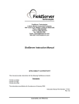
A Sierra Monitor Company
Driver Manual
(Supplement to the FieldServer Instruction Manual)
FS-8700-124 TIC UPS
APPLICABILITY & EFFECTIVITY
Effective for all systems manufactured after May 1, 2001
Driver Version:
1.01
Document Revision: 0
ProtoNode Driver Manual (FS-8700-124) rev 6.doc Manual
Table of Contents
TABLE OF CONTENTS
1.
2.
TIC UPS DESCRIPTION ................................................................................................. 3
DRIVER SCOPE OF SUPPLY ........................................................................................ 4
2.1.
Supplied by FieldServer Technologies for this driver ................................................... 4
2.2.
Provided by the Supplier of 3rd Party Equipment .......................................................... 4
2.2.1. Required 3rd Party Hardware ..................................................................................... 4
2.2.2. Required 3rd Party Software ....................................................................................... 4
2.2.3. Required 3rd Party Configuration ............................................................................... 4
3.
3.1.
4.
HARDWARE CONNECTIONS....................................................................................... 5
Hardware Connection Tips / Hints ................................................................................. 5
CONFIGURING THE FIELDSERVER AS A TIC UPS CLIENT .............................. 6
4.1.
Data Arrays/Descriptors ................................................................................................. 6
4.2.
Client Side Connection Descriptions ............................................................................. 7
4.3.
Client Side Node Descriptors ......................................................................................... 7
4.4.
Client Side Map Descriptors .......................................................................................... 8
4.4.1. FieldServer Related Map Descriptor Parameters ...................................................... 8
4.4.2. Driver Related Map Descriptor Parameters .............................................................. 8
4.5.
Map Descriptor Example. .............................................................................................. 9
4.5.1. Example 1.................................................................................................................... 9
4.5.2. Example 2.................................................................................................................... 9
APPENDIX A. COMMANDS SPECIFIC TO DEVICES ..................................................... 10
Appendix A.1. Client Read commands ................................................................................... 10
Appendix A.1.1. FAULT command: .................................................................................... 12
Appendix A.1.2. ALARM command: ................................................................................... 13
Appendix A.1.3. STATUS command: .................................................................................. 13
Appendix A.1.4. Commands supported by Different Models .............................................. 14
Appendix A.2. Client Write Commands ................................................................................. 14
Appendix A.2.1. Commands supported by different models. .............................................. 15
APPENDIX B. TROUBLESHOOTING TIPS ........................................................................ 16
Appendix B.1. Connection Tips & Hints ................................................................................ 16
ProtoCessor 1991 Tarob Court Milpitas, California 95035 USA Web:www.protocessor.com
Tel: 408.964.4433 Fax: 408.964.4425 Toll_Free: 800.317.8319 email: [email protected]
ProtoNode Driver Manual (FS-8700-124) rev 6.doc Manual
Page 3 of 17
1.
TIC UPS Description
The serial TIC UPS driver allows the ProtoNode to transfer data to and from devices over RS232 using TIC UPS protocol. The ProtoNode can emulate a Client.
This driver is intended for use with Toshiba models UPS.
It is intended to do the following:
Read information from the UPS such as battery life, voltages etc. This will be done in
user mode on the UPS.
Write information and commands such as shutdown commands to the UPS.
Advanced options such as reading/writing EEPROM is not supported. No date/time
reads or writes will be supported. No string type commands will be supported.
Max Nodes Supported
ProtoNode Mode
Nodes
Client
1
Server
1
Comments
As the Toshiba protocol only allows for 1:1 communication
at this stage, only 1 client is allowed per RS-232 port.
The server only serves for emulation purposes. It will have
a static address as per Toshiba spec.
ProtoCessor 1991 Tarob Court Milpitas, California 95035 USA Web:www.protocessor.com
Tel: 408.964.4433 Fax: 408.964.4425 Toll_Free: 800.317.8319 email: [email protected]
ProtoNode Driver Manual (FS-8700-124) rev 6.doc Manual
Page 4 of 17
2.
Driver Scope of Supply
2.1.
Supplied by FieldServer Technologies for this driver
FieldServer Technologies
PART #
FS-8917-02
FS-8917-03
FS-8700-124
Description
RJ45 to DB9F connector adapter.
RJ45 to DB9M connector adapter.
Driver Manual.
Provided by the Supplier of 3rd Party Equipment
2.2.
2.2.1.
Part #
-
2.2.2.
Required 3rd Party Hardware
Description
TIC UPS model
1600/1800/4200/G8000/G8000MM/G9000
Required 3rd Party Software
None
2.2.3.
Required 3rd Party Configuration
The baud rate of the UPS must match the configuration file of the ProtoNode.
ProtoCessor 1991 Tarob Court Milpitas, California 95035 USA Web:www.protocessor.com
Tel: 408.964.4433 Fax: 408.964.4425 Toll_Free: 800.317.8319 email: [email protected]
ProtoNode Driver Manual (FS-8700-124) rev 6.doc Manual
Page 5 of 17
3.
Hardware Connections
The ProtoNode is connected to the UPS as shown in connection drawing.
Configure the TIC UPS according to manufacturer’s instructions.
Toshiba UPS
TO
DB9M-02
DB9M-05
DB9M-03
DB9M
8917-03 WIRE LIST
FUNCTION FROM
Rx
RJ45-01
GND
RJ45-04
Tx
RJ45-08
COLOUR
GREY
GREEN
BLUE
8917-02 WIRE LIST
FUNCTION FROM
Rx
RJ45-01
GND
RJ45-04
Tx
RJ45-08
TO
DB9F-03
DB9F-05
DB9F-02
COLOUR
WHITE
GREEN
BLUE
(408)-262-2299
DB9F
PROTONODE
3.1.
PROTONODE
TOSHIBA UPS
CONNECTION DIAGRAM
BASE NAME:
FILE NAME: FS-8700-124
DATE: 10/10/07
BY:
MC
Hardware Connection Tips / Hints
The RTS/DTS signals are not used by the driver. Make sure they are not connected and
do not enable them in the configuration file.
The cable must be a NULL modem cable, i.e. the TX must be connected to the other
connector’s RX.
ProtoCessor 1991 Tarob Court Milpitas, California 95035 USA Web:www.protocessor.com
Tel: 408.964.4433 Fax: 408.964.4425 Toll_Free: 800.317.8319 email: [email protected]
ProtoNode Driver Manual (FS-8700-124) rev 6.doc Manual
Page 6 of 17
4.
Configuring the FieldServer as a TIC UPS Client
For a detailed discussion on FieldServer configuration, please refer to the FieldServer
Configuration Manual. The information that follows describes how to expand upon the factory
defaults provided in the configuration files included with the FieldServer (See “.csv” sample files
provided with the FieldServer).
This section documents and describes the parameters necessary for configuring the FieldServer
to communicate with a TIC UPS Server.
4.1.
Data Arrays/Descriptors
The configuration file tells the FieldServer about its interfaces, and the routing of data
required. In order to enable the FieldServer for TIC UPS communications, the driver
independent FieldServer buffers need to be declared in the “Data Arrays” section, the
destination device addresses need to be declared in the “Client Side Nodes” section, and the
data required from the servers needs to be mapped in the “Client Side Map Descriptors”
section. Details on how to do this can be found below.
Note that in the tables, * indicates an optional parameter, with the bold legal value being the
default.
Section Title
Data_Arrays
Column Title
Data_Array_Name
Data_Array_Format
Data_Array_Length
Function
Legal Values
Up to 15 alphanumeric
characters
Provide name for Data Array
Provide data format. Each Data
Array can only take on one format.
Number of Data Objects. Must be
larger than the data storage area
required by the Map Descriptors for
the data being placed in this array.
Float, Bit
1-10,000
Example
// Data Arrays
Data_Arrays
Data_Array_Name,
DA_AI_01,
DA_DI_01,
Data_Array_Format,
Float,
Bit,
Data_Array_Length
200
200
ProtoCessor 1991 Tarob Court Milpitas, California 95035 USA Web:www.protocessor.com
Tel: 408.964.4433 Fax: 408.964.4425 Toll_Free: 800.317.8319 email: [email protected]
ProtoNode Driver Manual (FS-8700-124) rev 6.doc Manual
Page 7 of 17
4.2.
Client Side Connection Descriptions
Section Title
Connections
Column Title
Protocol
Function
Specify which port the device
is connected to the ProtoNode
Specify protocol used
Baud*
Specify baud rate
Parity*
Data_Bits*
Stop_Bits*
Handshaking*
Poll _Delay*
Specify parity
Specify data bits
Specify stop bits
Specify hardware handshaking
Time between internal polls
Port
Legal Values
P1-P8
TOSHIBA_UPS, TOSH_UPS
1200–9600, standard baud rates
only (Vendor limitation)
Even
7
1
None
0-32000 seconds, 0.05 seconds
Example
//
Client Side Connections
Connections
Port, Protocol,
P1,
TOSH_UPS,
4.3.
Baud,
1200,
Parity,
Even,
Handshaking,
None,
Data_Bits
7
Poll_Delay
0.100s
Client Side Node Descriptors
Section Title
Nodes
Column Title
Node_Name
Protocol
Function
Provide name for node
Modbus station address of
physical server node
Specify protocol used
Node_Type
The model of the TIC UPS
Connection
Specify which port the device is
connected to the ProtoNode
Node_ID
Legal Values
Up to 32 alphanumeric characters
1
TOSH_UPS, TOSHIBA_UPS
1600, 1800, 4200, G8000,
G8000MM, G9000
P1-P81
1
Not all ports shown are necessarily supported by the hardware. Consult the appropriate Instruction manual for
details of the ports available on specific hardware.
ProtoCessor 1991 Tarob Court Milpitas, California 95035 USA Web:www.protocessor.com
Tel: 408.964.4433 Fax: 408.964.4425 Toll_Free: 800.317.8319 email: [email protected]
ProtoNode Driver Manual (FS-8700-124) rev 6.doc Manual
Page 8 of 17
Example
// Client Side Nodes
Nodes
Node_Name,
PLC 1,
4.4.
Node_ID,
1,
Protocol,
TOSH_UPS,
Node_Type,
1600,
Connection
P1
Client Side Map Descriptors
4.4.1.
FieldServer Related Map Descriptor Parameters
Column Title
Function
Map_Descriptor_Name Name of this Map Descriptor
Data_Array_Name
Data_Array_Offset
Function
4.4.2.
Column Title
Name of Data Array where
data is to be stored in the
FieldServer
Starting location in Data
Array
Function of Client Map
Descriptor
Legal Values
Up to 32 alphanumeric
characters
One of the Data Array names
from “Data Array” section
above
0 to maximum specified in
“Data Array” section above
RDBC, WRBC, WRBX
Driver Related Map Descriptor Parameters
Function
Name of Node to fetch
Node_Name
data from
Type of information
Toshiba_Command on UPS
Length of Map
Length
Descriptor
Legal Values
One of the node names specified in
“Client Node Descriptor” above
OV1, OV2, OV3 etc (Appendix A)
1 – All value commands
24 – All bit commands
ProtoCessor 1991 Tarob Court Milpitas, California 95035 USA Web:www.protocessor.com
Tel: 408.964.4433 Fax: 408.964.4425 Toll_Free: 800.317.8319 email: [email protected]
ProtoNode Driver Manual (FS-8700-124) rev 6.doc Manual
4.5.
Map Descriptor Example.
4.5.1.
//
Example 1
Client Side Map Descriptors
Map_Descriptors
Map_Descriptor_Name,
A1,
Data_Array_Name,
DA_AI_01,
For all commands except
FAULT and ALARM,
ensure that the
Data_Array_Name points
to an array of type float.
4.5.2.
//
Page 9 of 17
Data_Array_Offset,
0,
Function,
RDBC,
Node_Name,
Node_A,
Make sure the Toshiba
command supports the
selected function.
Toshiba_Command,
OV1,
Length,
1,
Scan_Interval
5
All commands except
ALARM and FAULT
have length 1.
For a list of
commands, see
Appendix A
Example 2
Client Side Map Descriptors
Map_Descriptors
Map_Descriptor_Name,
B1,
B2,
B3,
Data_Array_Name,
DA_DI_01,
DA_DI_01,
DA_DI_01,
For ALARM and
FAULT, use bit
arrays
Data_Array_Offset,
23,
15,
0,
Function,
RDBC,
RDBC,
RDBC,
Node_Name,
Node_A,
Node_A,
Node_A,
Use the offset to read a specific bit or
start reading at a specific bit. Use in
conjunction with length. Max value is
23.
Toshiba_Command,
ALARM,
ALARM,
ALARM,
Length,
1,
4,
23,
Scan_Interval
5
5
5
Specify number of bits to
read. Maximum for Offset
+ Length is 23.
ProtoCessor 1991 Tarob Court Milpitas, California 95035 USA Web:www.protocessor.com
Tel: 408.964.4433 Fax: 408.964.4425 Toll_Free: 800.317.8319 email: [email protected]
ProtoNode Driver Manual (FS-8700-124) rev 6.doc Manual
Page 10 of 17
Appendix A. Commands Specific to Devices
Appendix A.1. Client Read commands
The following commands are supported with the RDBC function.
ProtoCessor 1991 Tarob Court Milpitas, California 95035 USA Web:www.protocessor.com
Tel: 408.964.4433 Fax: 408.964.4425 Toll_Free: 800.317.8319 email: [email protected]
ProtoNode Driver Manual (FS-8700-124) rev 6.doc Manual
Page 11 of 17
Command
ALARM
BC
BECR
BEMR
BLR
BPV1
BPV2
BPV3
BPC
BPFREQ
BRHT
BT
BVP
DCBV
FAULT
IC1
IC2
IC3
IFRQ
IV1
IV2
IV3
OC1
OC2
OC3
OFRQ
OLP1
OLP2
OLP3
OV1
OV2
OV3
SOB
SAD
OV12
OV23
OV31
Description
Alarm data
Battery current
Battery estimated charge remaining
Battery estimated minutes remaining
Battery life remaining
Bypass voltage phase 1
Bypass voltage phase 2
Bypass voltage phase 3
Bypass current
Bypass frequency
Battery rated holding time
Battery temperature
Battery voltage percentage
DC bus voltage
Fault data
Input current phase 1
Input current phase 2
Input current phase 3
Input frequency
Input voltage phase 1
Input voltage phase 2
Input voltage phase 3
Output current phase 1
Output current phase 2
Output current phase 3
Output frequency
Output load percent phase 1
Output load percent phase 2
Output load percent phase 3
Output voltage phase 1
Output voltage phase 2
Output voltage phase 3
Seconds on battery
Shutdown after delay
Output voltage between phase 1 & 2
Output voltage between phase 2 & 3
Output voltage between phase 3 & 1
ProtoCessor 1991 Tarob Court Milpitas, California 95035 USA Web:www.protocessor.com
Tel: 408.964.4433 Fax: 408.964.4425 Toll_Free: 800.317.8319 email: [email protected]
ProtoNode Driver Manual (FS-8700-124) rev 6.doc Manual
Page 12 of 17
Appendix A.1.1.
FAULT command:
Stored in bits, make sure array’s length is 24 and its type is bits.
Bit #
Bit 23:
Bit 22:
Bit 21:
Bit 20:
Bit 19:
Bit 18:
Bit 17:
Bit 16:
Bit 15:
Bit 14:
Bit 13:
Bit 12:
Bit 11:
Bit 10:
Bit 9:
Bit 8:
Bit 7:
Bit 6:
Bit 5:
Bit 4:
Bit 3:
Bit 2:
Bit 1:
Bit 0:
Function
Not used
1
Input over current
DC over current
DC bus over voltage
DC bus under voltage
Phase rotation error
DC Bus imbalance
Not used
1
EEPROM error
Battery or charger circuit fault
Battery overheat
UPS overheat
0
Fuse has opened
Not used
1
Inverter over current
UPS overload
Inverter overload
Inverter under voltage
Overload 110% load
Inverter over voltage
ProtoCessor 1991 Tarob Court Milpitas, California 95035 USA Web:www.protocessor.com
Tel: 408.964.4433 Fax: 408.964.4425 Toll_Free: 800.317.8319 email: [email protected]
ProtoNode Driver Manual (FS-8700-124) rev 6.doc Manual
Page 13 of 17
Appendix A.1.2.
ALARM command:
Stored in bits, make sure array’s length is 24 and its type is bits.
Bit #
Bit 23:
Bit 22:
Bit 21:
Bit 20:
Bit 19:
Bit 18:
Bit 17:
Bit 16:
Bit 15:
Bit 14:
Bit 13:
Bit 12:
Bit 11:
Bit 10:
Bit 9:
Bit 8:
Bit 7:
Bit 6:
Bit 5:
Bit 4:
Bit 3:
Bit 2:
Bit 1:
Bit 0:
Description
Not used
1
Low battery voltage
Battery replacement alarm
Parallel running mode
0
0
UPS lifetime alarm
Not used
1
Asynchronous operation
Ambient overheat
Overload accumulation started
0
0
0
Not used
1
Countdown started for shutdown
0
0
0
0
0
Appendix A.1.3.
STATUS command:
Stored in bits, make sure array’s length is 8 and its type is bits.
Bit #
Bit 7:
Bit 6:
Bit 5:
Bit 4:
Bit 3:
Bit 2:
Bit 1:
Bit 0:
Description
Not used
1
UPS fault detected
Input voltage out of spec
Low battery voltage detected
UPS output from bypass
UPS output from inverter
UPS input and output voltage sync
ProtoCessor 1991 Tarob Court Milpitas, California 95035 USA Web:www.protocessor.com
Tel: 408.964.4433 Fax: 408.964.4425 Toll_Free: 800.317.8319 email: [email protected]
ProtoNode Driver Manual (FS-8700-124) rev 6.doc Manual
Page 14 of 17
Appendix A.1.4.
1600:
ALARM
BC
BEMR
BLR
BPV1
BPC
BPFREQ
BRHT
BT
BVP
FAULT
IC1
IFRQ
IV1
OC1
OFRQ
OLP1
OV1
SAD
STATUS
Commands supported by Different Models
1800
ALARM
BC
BECR
BEMR
BLR
BPV1
BPC
BPFREQ
BRHT
BT
BVP
DCBV
FAULT
IC1
IFRQ
IV1
OC1
OFRQ
OLP1
OV1
SOB
SAD
STATUS
4200
BC
BPV1
BPV2
BPV3
BPC
BPFREQ
BRHT
BVP
DCBV
FAULT
IC1
IC2
IC3
IFRQ
IV1
IV2
IV3
OC1
OC2
OC3
OFRQ
OLP1
OLP2
OLP3
OV1
OV2
OV3
SAD
STATUS
G8000 & G8000MM
BC
BECR
BPV1
BPV2
BPV3
BPC
BPFREQ
BRHT
BVP
DCBV
FAULT
IC1
IC2
IC3
IFRQ
IV1
IV2
IV3
OC1
OC2
OC3
OFRQ
OLP1
OLP2
OLP3
OV1
OV2
OV3
STATUS
G9000
BC
BECR
BPC
BPFREQ
BRHT
BVP
DCBV
FAULT
IC1
IC2
IC3
IFRQ
IV1
IV2
IV3
OC1
OC2
OC3
OFRQ
OLP1
OLP2
OLP3
OV1
OV2
OV3
OV12
OV23
OV31
STATUS
Appendix A.2. Client Write Commands
The following commands are supported with the WRBC functions.
ProtoCessor 1991 Tarob Court Milpitas, California 95035 USA Web:www.protocessor.com
Tel: 408.964.4433 Fax: 408.964.4425 Toll_Free: 800.317.8319 email: [email protected]
ProtoNode Driver Manual (FS-8700-124) rev 6.doc Manual
Page 15 of 17
Command
SAD
BTEST
Description
Shutdown after delay.
Battery Test2
Appendix A.2.1.
1600:
SAD
BTEST
2
Commands supported by different models.
1800
SAD
BTEST
4200
SAD
BTEST
G8000 & G8000MM, G9000
No Write commands supported
Please note that due to battery health, this point can only be tested as specified by TIC
ProtoCessor 1991 Tarob Court Milpitas, California 95035 USA Web:www.protocessor.com
Tel: 408.964.4433 Fax: 408.964.4425 Toll_Free: 800.317.8319 email: [email protected]
ProtoNode Driver Manual (FS-8700-124) rev 6.doc Manual
Page 16 of 17
Appendix B. Troubleshooting Tips
Appendix B.1. Connection Tips & Hints
1. What should the baud rate in my configuration file be set to?
Consult the UPS manual for the default baud rate of your UPS.
ProtoCessor 1991 Tarob Court Milpitas, California 95035 USA Web:www.protocessor.com
Tel: 408.964.4433 Fax: 408.964.4425 Toll_Free: 800.317.8319 email: [email protected]
ProtoNode Driver Manual (FS-8700-124) rev 6.doc Manual
Page 17 of 17
THIS PAGE INTENTIONALLY LEFT BLANK
ProtoCessor 1991 Tarob Court Milpitas, California 95035 USA Web:www.protocessor.com
Tel: 408.964.4433 Fax: 408.964.4425 Toll_Free: 800.317.8319 email: [email protected]