1
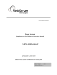
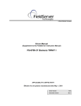
A Sierra Monitor Company
Driver Manual
(Supplement to the FieldServer Instruction
Manual)
FS-8700-83 Gamewell Serial Driver
APPLICABILITY & EFFECTIVITY
Effective for all systems manufactured after May 1, 2001
FS-8700-83 Gamewell
Index
TABLE OF CONTENTS
1.
GAMEWELL SERIAL DRIVER DESCRIPTION ................................................................................... 1
2.
DRIVER SCOPE OF SUPPLY .............................................................................................................. 1
2.1
2.2
SUPPLIED BY FIELDSERVER TECHNOLOGIES FOR THIS DRIVER ............................................................ 1
PROVIDED BY USER ........................................................................................................................... 1
3.
HARDWARE CONNECTIONS.............................................................................................................. 2
4.
CONFIGURING THE FIELDSERVER AS A GAMEWELL SERIAL DRIVER CLIENT ........................ 3
4.1
DATA ARRAYS .................................................................................................................................. 3
4.2
CLIENT SIDE CONNECTIONS .............................................................................................................. 4
4.3
CLIENT SIDE NODES ......................................................................................................................... 5
4.4
CLIENT SIDE MAP DESCRIPTORS ....................................................................................................... 6
FieldServer Related Map Descriptor Parameters.................................................................................. 6
Driver Related Map Descriptor Parameters........................................................................................... 6
Timing Parameters................................................................................................................................. 7
Map Descriptor Example 1 – Store data from incoming messages. ..................................................... 8
Map Descriptor Example 2 – Send a Reset / Ack / Silence Command................................................. 9
5.
CONFIGURING THE FIELDSERVER AS A GAMEWELL SERIAL DRIVER SERVER .................... 10
6.
ADVANCED TOPICS .......................................................................................................................... 10
6.1
DRIVER LIMITATIONS & EXCLUSIONS ................................................................................................ 10
6.2
DATA TYPES ................................................................................................................................... 10
6.3
STATUS TYPES AND VALUES ............................................................................................................ 11
Adding a New Status Type .................................................................................................................. 12
6.4
WHEN DO DATA ARRAYS GET CLEARED (RESET) .............................................................................. 12
6.5
ACTION TYPES ................................................................................................................................ 12
Adding new Action Types .................................................................................................................... 15
6.6
ADVANCED MAP DESCRIPTOR EXAMPLES ........................................................................................ 16
Example 1 : Filtering Data.................................................................................................................... 16
Example 2 : Action Numbers ............................................................................................................... 17
Example 3 : Action Bits ........................................................................................................................ 18
Example 4 : Ignored Messages ........................................................................................................... 19
7.
DRIVER NOTES .................................................................................................................................. 20
7.1
7.2
8.
IC_TIMEOUT ................................................................................................................................... 20
DRIVER STATS ................................................................................................................................ 20
REVISION HISTORY................................................................ ERROR! BOOKMARK NOT DEFINED.
FieldServer Technologies 1991 Tarob Court Milpitas, California 95035 USA Web:www.fieldserver.com
Tel: (408) 262-2299 Fax: (408) 262-9042 Toll_Free: 888-509-1970 email: [email protected]
FS-8700-83 Gamewell
Page 1 of 24
1. Gamewell Serial Driver Description
The Gamewell Serial Driver allows the FieldServer to accept messages generated by a
Gamewell 600 Series Panel as well as ‘Smartnet Data Stream’ messages generated by a
Gamewell Smartnet terminal.
All Gamewell 600 Series Fire Alarm panels are equipped with a serial port, which produces
panel, circuit or device status messages. This driver is designed to process these messages
and store this status information in numeric form. The numeric value will indicate the type of
event being reported and the storage location in the FieldServer’s data arrays is (configurable
&) dependent on the origin of the message (panel / circuit / device). Additional information such
as event date and time and descriptions are ignored.
The driver is capable of supporting a panel configured to supervise the port by responding to the
panel’s supervision queries.
This is a passive client driver. The driver listens passively for unsolicited messages produced by
the Gamewell panel. This definition is not strictly true because the driver is capable of sending
the panel three messages: Ack, Silence and Reset.
Design Basis: Gamewell serial port protocol specification “IF 600r7 Message Stream” (not
dated) and “SmartNet Data stream information” (not dated).
The driver is capable of exposing communication statistics in a FieldServer Data Array so that a
remote device can monitor them.
2. Driver Scope of Supply
2.1
Supplied by FieldServer Technologies for this driver
FieldServer
Technologies
PART #
FS-8917-16
2.2
DESCRIPTION
RS-485/RS-232 Pigtail for RJ45 port
Driver Manual.
Provided by user
PART #
DESCRIPTION
Gamewell Panel with SIM232 interface
FieldServer Technologies 1991 Tarob Court Milpitas, California 95035 USA Web:www.fieldserver.com
Tel: (408) 262-2299 Fax: (408) 262-9042 Toll_Free: 888-509-1970 email: [email protected]
FS-8700-83 Gamewell
Page 2 of 24
3. Hardware Connections
The bridge is connected to the Gamewell panel as shown below.
Configure the Gamewell panel according to manufacturer’s instructions
FIELDSERVER
RS232 PORT
GAMEWELL
SIM 232
BOARD
FS-Rx
RJ45-01
BROWN
XMT
FS-Tx
FS-COM
FS-8915-10
COM
RCV
COM2
GND
RJ45-04
BLUE/WHITE
RJ45-08
ORANGE/WHITE
(408)-262-2299
GAMEWELL
CONNECTION DIAGRAM
BASE NAME:
FILE NAME: T28700-83 .VSD
DATE:6/4/02
BY:
MN
FieldServer Technologies 1991 Tarob Court Milpitas, California 95035 USA Web:www.fieldserver.com
Tel: (408) 262-2299 Fax: (408) 262-9042 Toll_Free: 888-509-1970 email: [email protected]
FS-8700-83 Gamewell
Page 3 of 24
4. Configuring the FieldServer as a Gamewell Serial Driver Client
For a detailed discussion on FieldServer configuration, please refer to the FieldServer
Configuration Manual. The information that follows describes how to expand upon the factory
defaults provided in the configuration files included with the FieldServer (See “.csv” files on the
driver diskette).
This section documents and describes the parameters necessary for configuring the FieldServer
to communicate with a Gamewell Serial Driver Server
The configuration file tells the FieldServer about its interfaces, and the routing of data required.
In order to enable the FieldServer for Gamewell Serial Driver communications, the driver
independent FieldServer buffers need to be declared in the “Data Arrays” section, the
destination device addresses need to be declared in the “Client Side Nodes” section, and the
data required from the servers needs to be mapped in the “Client Side Map Descriptors”
section. Details on how to do this can be found below.
Note that in the tables, * indicates an optional parameter, with the bold legal value being the
default.
4.1
Data Arrays
Section Title
Data_Arrays
Column Title
Data_Array_Name
Function
Provide name for Data Array
Data_Format
Provide data format. Each data array can
only take on one format.
Data_Array_Length
Number of Data Objects. Must be larger
than the data storage area required for
the data being placed in this array.
Legal Values
Up to 15 alphanumeric
characters
FLOAT, BIT, UInt16, SInt16,
Packed_Bit, Byte,
Packed_Byte,
Swapped_Byte
1-10,000
Example
//
Data Arrays
//
Data_Arrays
Data_Array_Name,
DA_AI_01,
DA_AO_01,
DA_DI_01,
DA_DO_01,
Data_Format,
UInt16,
UInt16,
Bit,
Bit,
Data_Array_Length
200
200
200
200
FieldServer Technologies 1991 Tarob Court Milpitas, California 95035 USA Web:www.fieldserver.com
Tel: (408) 262-2299 Fax: (408) 262-9042 Toll_Free: 888-509-1970 email: [email protected]
FS-8700-83 Gamewell
4.2
Page 4 of 24
Client Side Connections
Section Title
Connections
Column Title
Port
Baud
Function
Specify which port the device is
connected to the Bridge
Specify baud rate
Parity*
The driver supports all standard
baud rates 110 – 115200.
Gamewell panels only support a
baud rate of 2400.
Specify parity
Legal Values
P1-P8, R1-R2
2400
None
The driver supports the following
options. Even, Odd, None, Mark,
Space
Data_Bits*
Stop_Bits*
Protocol
Handshaking*
Poll _Delay*
IC_Timeout
The Gamewell panels only
support the use of no parity.
Specify data bits
Specify stop bits
Specify protocol used
Specify hardware handshaking
Time between internal polls
This driver does not use an inter
character timeout system. Failing
to set the IC_Timeout to zero will
result in driver errors.
8
1
Gamewell
None
0-32000 seconds
default 1 second
0
Example
//
Client Side Connections
Connections
Port, Baud, Parity, Protocol, Handshaking, Poll_Delay, IC_Timeout
P8, 9600, None, Gamewell, None
, 0.100s , 0
FieldServer Technologies 1991 Tarob Court Milpitas, California 95035 USA Web:www.fieldserver.com
Tel: (408) 262-2299 Fax: (408) 262-9042 Toll_Free: 888-509-1970 email: [email protected]
FS-8700-83 Gamewell
4.3
Page 5 of 24
Client Side Nodes
Section Title
Nodes
Column Title
Node_Name
Function
Provide name for node
Node_ID
Gamewell panel node address.
Legal Values
Up to 32 alphanumeric
characters
0-256
The Node Id has no meaning
when the FieldServer is
connected directly to Gamewell
panel. When connecting to a
Gamewell panel directly always
set the Node_ID to zero. When
connecting to a Gamewell
SmartNet terminal. The
Node_ID is important and
should correspond to the
Node_ID’s of the panel’s
connected to the SmartNet
terminal.
Protocol
Port
Specify protocol used
Specify which port the device is
connected to the FieldServer.
Gamewell
P1-P8, R1-R2
The use of R1 and R2 is only
appropriate when a 232/485
converter is used. The
Gamewell panels only have a
232 port available for
connection.
Example
//
Client Side Nodes
Nodes
Node_Name, Node_ID, Protocol, Port
Panel1 , 0
, Gamewell, P8
FieldServer Technologies 1991 Tarob Court Milpitas, California 95035 USA Web:www.fieldserver.com
Tel: (408) 262-2299 Fax: (408) 262-9042 Toll_Free: 888-509-1970 email: [email protected]
FS-8700-83 Gamewell
4.4
Page 6 of 24
Client Side Map Descriptors
FieldServer Related Map Descriptor Parameters
Column Title
Map_Descriptor_Name
Function
Name of this Map Descriptor
Data_Array_Name
Name of Data Array where data
is to be stored in the Bridge
Starting location in Data Array
Data_Array_Location
Function
Function of Client Map
Descriptor.
Legal Values
Up to 32 alphanumeric
characters
One of the Data Array names
from “Data Array” section above
0 to maximum specified in
“Data Array” section above
Passive, WRBC, WRBX
Reads (rdbc / rdb ) are not
allowed. The use of WRBX is
recommended for the ack /
silence / reset functions. A
message will be generated
each time the value in the
associated array is updated
(even if the value stays the
same.)
Driver Related Map Descriptor Parameters
Column Title
Node_Name
Function
Name of Node to fetch data
from
Data_Type
Data type
This parameter is only required
for passive / server map
descriptors.
The Data Type determines the
type of data that gets stored
when a message get received.
The Data Type corresponds to
the ‘Status’ field in a Gamewell
message.
Additional information is
provided in section 6.2
Legal Values
One of the node names
specified in “Client Node
Descriptor” above
Any
Alarms
Faults
Events
Bus
Comm
Control
Ack
Signal Silence
Troubles
Supervisories
Action_Numbers
Action_Bits
Dump
FieldServer Technologies 1991 Tarob Court Milpitas, California 95035 USA Web:www.fieldserver.com
Tel: (408) 262-2299 Fax: (408) 262-9042 Toll_Free: 888-509-1970 email: [email protected]
FS-8700-83 Gamewell
Length
Address
Ckt
Page 7 of 24
Length of Map Descriptor
Controls how many elements of the data
array are controlled by the map
descriptor.
This commonly used parameter has no
meaning for this driver. If specified it is
best set to zero.
Specify the circuit number whose
message will get stored using this map
descriptor.
1 – 1000
0
Panel , 1 ,2 , 3 …. 131
Use the keyword ‘Panel’ if the you wish
to store data from a panel. All messages
which do not contain the keyword ‘Ckt’ in
the action field are deemed to be panel
messages.
Dev
Valid panel numbers are 1-131
The starting device number for the map
descriptor. The length determines how
many devices can have their data stored
using this map descriptor.
0 , 1 , 2 … 126
Valid circuit numbers are 1-126 but this
driver allows a device number of zero to
allow for the storage of messages which
don’t specify a device number.
Ty
Clear_On_Reset
Store_As*
Gamewell_Func*
Only relevant when the
Data_Type=’Dump’
This tells the driver to store ignored
messages in ASCII format or to dump
them in ASCII format in the error log.
Only relevant when the function is write.
This parameter tell the driver what type
of command to send to the panel.
Yes, No
AsciiLog
ASCII
Value
Reset
Ack
Silence
You should always Ack before you
silence the panel.
Timing Parameters
Column Title
Scan_Interval
Function
Rate at which data is polled
Legal Values
>0.1s
FieldServer Technologies 1991 Tarob Court Milpitas, California 95035 USA Web:www.fieldserver.com
Tel: (408) 262-2299 Fax: (408) 262-9042 Toll_Free: 888-509-1970 email: [email protected]
FS-8700-83 Gamewell
Page 8 of 24
Map Descriptor Example 1 – Store data from incoming messages.
This example illustrates typical map descriptor uses to store data from panel generated messaged.
As all these map descriptors have their Clear_On_Reset field set to yes, when a panel reset message is received all the data in the controlled
arrays will be set to zero When a point reports its own state as normal the driver will set the appropriate element of the appropriate array to zero
to indicate the normal state..
Data is stored, first by finding a map descriptor with the correct circuit number. If the message doesn’t contain a circuit number then it is assumed
to be from the panel itself. If a message contain a CKT number and no DEV number then the driver assumes the device number is zero. The
storage location is based on the device number – it is used as an offset into the array.
Map_Descriptors
Map_Descriptor_Name,
Panel_data
,
Ckt1_data01
,
Ckt2_data01
,
Ckt3_data01
,
Data_Array_Name,
DA_STATUS
,
DA_STATUS
,
DA_STATUS
,
DA_STATUS
,
In this example all the
data for all these
circuits is stored in one
array.
The offset is used to
control the location in
the array.
Data_Array_Offset,
000
,
200
,
400
,
600
,
These map descriptors
are all passive. We
cannot poll the panel
but we can wait
passively for the panel
to send us messages.
Function,
passive ,
passive ,
passive ,
passive ,
Node_Name,
panel1
,
panel1
,
panel1
,
panel1
,
You need one map
descriptor for each
circuit / panel.
ckt ,
Panel,
1
,
2
,
3
,
Dev, Length, Data_Type , Clear_On_Reset
0 ,100
, Any
, Yes
0 ,100
, Any
, Yes
0 ,100
, Any
, Yes
0 ,100
, Any
, Yes
The length determines
the number of devices
that can be processed
using the map
descriptor.
Say a message for
Ckt:2 Dev:20 is
received. The driver
looks at the device
number and the length
to see if the range of
devices covers the
incoming message. I
this case the data
would be stored at
offset 20 in the map
descriptor.
Because the Data Type
is ‘Any’ the driver will
set an array element
non-zero if any
messages indicate that
the point in not in a
normal condition.
FieldServer Technologies 1991 Tarob Court Milpitas, California 95035 USA Web:www.fieldserver.com
Tel: (408) 262-2299 Fax: (408) 262-9042 Toll_Free: 888-509-1970 email: [email protected]
FS-8700-83 Gamewell
Page 9 of 24
Map Descriptor Example 2 – Send a Reset / Ack / Silence Command.
This example illustrates three map descriptors used to send commands to the panel. These are the only active map descriptors that can be used
with the Gamewell Serial Driver.
These map descriptors use the WRBX function. When the 1st element (because
doesn’t change, then the driver will send the command to the panel.
Data_Array_Offset
= 0 ) has its value updated, even if the value
Note that you are required to send an Ack before you can send a silence command. The driver does not clear the trigger by setting the array
element back to zero. The panel does not send a message acknowledging receipt of the command, thus the driver cannot provide positive
confirmation.
Map_Descriptors
Map_Descriptor_Name,
Ack_md
,
Sil_md
,
Res_md
,
Data_Array_Name,
DA_ACK
,
DA_SILENCE
,
DA_RESET
,
Data_Array_Offset,
0
,
0
,
0
,
Length,
1
,
1
,
1
,
Function,
wrbx
,
wrbx
,
wrbx
,
Node_Name,
panel1
,
panel1
,
panel1
,
Gamewell_Func
Ack
Silence
Reset
Use one of these
keywords.
By using a wrbx you can
have the driver send the
command when the array
is updated.
Thus, to trigger any of
these commands have the
remote device send a
value to the 1st element of
the above data arrays.
FieldServer Technologies 1991 Tarob Court Milpitas, California 95035 USA Web:www.fieldserver.com
Tel: (408) 262-2299 Fax: (408) 262-9042 Toll_Free: 888-509-1970 email: [email protected]
FS-8700-83 Gamewell
Page 10 of 24
5. Configuring the FieldServer as a Gamewell Serial Driver Server
The Gamewell Serial Driver provides limited server functionality. This has been developed to allows for
automated testing and Quality Assurance. It is not supported or documented however, at a client’s
request it can be extended & documented (typically at an additional cost.)
6. Advanced Topics
6.1
Driver Limitations & Exclusions
The driver does not support scaling when data is stored in a data array. The keywords
‘Data_Array_Low_Scale, Data_Array_High_Scale, Device_Low_Scale, Device_High_Scale’
have no meaning for this driver. The reason for this is that the values stored by the driver have
specific meanings based on parsing the message. Scaling is only applicable in drivers which read
and write values from the remote device.
6.2
Data Types
Messages contain Status and Action information. The status information indicated the state of a
device / circuit / panel. The action information describe the event that generated the message.
By specifying one of the following Data_Types you can filter the incoming messages so that on
certain types of messages update certain data arrays. For example, if you are only interested in
storing data from messages that report an alarm then set the Data_Tupe of that map descriptor to
‘Alarms’. If you don’t care about the particular state then use the Data_Type of ‘Any’. The driver
will set the values of the array elements non-zero if any not-normal states are reported.
Data_Type
Any
Alarms
Faults
Events
Bus
Comm
Control
Ack
Signal Silence
Troubles
Supervisories
Action_Numbers
Action_Bits
Dump
Status
Status:ALARM
Status:FAULT
Status:EVENT
Status:BUS
Status:COMM
Status:CONTROL
Status:ACK
Status:SIG SIL
Status:FAULT
Status:EVENT and Action contains "Supv. Event in"
Note #
1
2
2
2
2
2
2
2
2
2
2
3
4
5
Notes:
FieldServer Technologies 1991 Tarob Court Milpitas, California 95035 USA Web:www.fieldserver.com
Tel: (408) 262-2299 Fax: (408) 262-9042 Toll_Free: 888-509-1970 email: [email protected]
FS-8700-83 Gamewell
Page 11 of 24
1. If the Data Type is ‘Any’ then the map descriptor will be used to store data from message with
any status.
2. The state reported is filtered and must match the Data_Type for the associated array to be
updated. For example, if the Data_Type of a MapDesc is ‘Alarms’ and a message is received that
reports a Fault then the map descriptor will not be used to store the data from the message.
3. Normally, user’s are interested in the Status of a device / circuit / panel but they may also be
interested in the cause (or the ‘action’ in Gamewell terminology) of the message. When you
specify the Data_Type as ‘Action Numbers’ then the driver will store a value which can be used to
look up the action that produced the message. The most recent action number is stored over any
older value. (The driver does not provide an event log.)
4. Instead of storing a value to indicate the action, the driver can set a bit whose offset indicates
the action. For example, action 30 will cause the 30th bit to be set. Action bits are stored
retentively. This means that when a new action is reported the previous bits are left set and a new
bit is set too.
5. What happens if a message arrives that reports an alarm and you don’t have a map descriptor
with a Data_Type capable of storing an alarm. You can make a catch all map descriptor and use
the ‘Dump’ Data_Type to tell the driver to store the whole message in ASCII format in a data
array so that you can inspect it. You can also use this map descriptor to tell the driver to dump the
ignored message to the error log.
6.3
Status Types and Values
Generally, the driver stores non-zero values to indicate the state of a device / circuit / panel based
on the ‘status’ field of the incoming message. The specific non-zero value can be found in the
following table. The value have been chosen so that they correspond to different bits.
Status
Alarm
Fault
Event
Bus
Comm
Control
Ack
Sig Sil
Supv
Genr
Value Stored
1
2
4
8
16
32
64
128
512
1024
Thus if a map descriptor has its Data_Type = ‘Any’ and two messages are received , one an
alarm and one an event, then the value of the array element will be set to 1 + 4 = 5. Thus the
value is non-zero to report the not-normal state but inspection of the value allows you to
determine the specific stat.
The value’s can be changed by using the method below to add, but when you add, use the
existing name and a new value.
FieldServer Technologies 1991 Tarob Court Milpitas, California 95035 USA Web:www.fieldserver.com
Tel: (408) 262-2299 Fax: (408) 262-9042 Toll_Free: 888-509-1970 email: [email protected]
FS-8700-83 Gamewell
Page 12 of 24
When comparing these keywords to the data in the Status field of the message the driver only
compares the first three characters. The comparison is case insensitive.
Adding a New Status Type
The fragment of a CSV file displayed below illustrates how to change the value associated with
‘BUS’ to 9 and adds two new Status types, Fred and Ginger.
Driver_Table
Gamewell_Status_String,
BUS
,
FRED
,
GINGER
,
Gamewell_Status_Value,
9
,
100
,
101
,
Protocol
Gamewell
Gamewell
Gamewell
There is a limitation in the use of new status types. They can only be stored using map
descriptors with the Data_Type set to ‘Any’.
The driver can store a maximum of 100 status types. The maximum length of the string is 9
characters.
6.4
When do Data Arrays get cleared (Reset)
When the Gamewell Panel is reset then the driver is able to clear the arrays. The way that the
panel works is that when a reset is performed send the following message
Status:NORMAL
System Idle
08/31/95 16:23
After this message the panel then sends messages for all points that are not in a normal state.
The driver uses the parameter ‘Clear_On_Reset’ to determine what gets cleared. If a map
descriptor has this parameter set to ‘Yes’ then the arrays elements controlled by the
Data_Array_Offset and the Length are set to zero.
This provides a good technique of synchronizing the panel and the FieldServer. When you
restart the FieldServer you should push the reset button on the panel so that the panel sends
messages for all points that are not in a normal state. If you don’t do this, and some points are in
a not-normal state then the FieldServer will not know about them until their state changes This is
potentially dangerous.
6.5
Action Types
Typically messages from the panel are contain not only the status of a point but also describe the
action that caused the state to change.
FieldServer Technologies 1991 Tarob Court Milpitas, California 95035 USA Web:www.fieldserver.com
Tel: (408) 262-2299 Fax: (408) 262-9042 Toll_Free: 888-509-1970 email: [email protected]
FS-8700-83 Gamewell
Page 13 of 24
Based on the table below if a message contains the string ‘Fire Alarm in’ then the action number
will be stored as 11.
Value Action
255
System Setup
1 Skip System I/O Assignments
2 Begin System I/O Assignments
3 Programming Mode Entered
4 Exit Program Mode
Control
5 Commencing System Reset
6 System Idle
7 System Acknowledged
8 Signals Deactivated
Description
Driver did not recognize action type
System power up
System programming itself
Ignore any data from this point until "Exit Program
Mode" is received
See Programming Mode Entered
System reset button has been depressed
System reset completed system is normal
System Acknowledge button depressed
System Signal Silence button depressed Audibles
Silencing
System Signal Silence button depressed Audibles
reactivating
System automatically silenced the audible signals
9 Signals Activated
10 Signals Silenced Automatically
Fire Alarm
11 Fire Alarm in
Supervisory
12 Supv. Event in
Generic
13 Genr. Event in
Security Alarm
14 Security Alarm in
Pre Alarm
15 Ver. Seq. in
Verification sequence started
16 Pos Al. Seq. in
Positive Alarm Sequence started
17 Pre-Alarm in
Pre alarm present
Fault
18 Alarm Tested in
Message during walk test
19 AtoD Malfunction
System Problem
20 LCD Malfunction
System Problem
22 System In Walk Test
Start partial or Full system walk test mode
23 System Out Of Walk Test
Finished system walk test mode
24 System l/Os By Passed
Bypass system circuits or devices
25 All By Passed I/Os Cleared
System not bypassed
26 I/0 Bypassed,
Starts ID of Circuit or point bypassed
27 Remote Annunciators Not Responding System Problem
28 Remote Annunciators OK
System Problem Restored
29 Key Stuck in
System Problem
30 Display Missing for
System Problem
31 Bad Card @
System Problem
32 Card Missing @
System Problem
FieldServer Technologies 1991 Tarob Court Milpitas, California 95035 USA Web:www.fieldserver.com
Tel: (408) 262-2299 Fax: (408) 262-9042 Toll_Free: 888-509-1970 email: [email protected]
FS-8700-83 Gamewell
33 New Card Detected @
34 Out of Memory Assigning
35 I/O Restored
36 Trouble Tested in
37 Trouble in
38 Output Shorted in
39 Dup. Dev. in
40 Dev. Missing in
41 Type Mismatch
42 Dev. Dirty in
43 No Response from Analog CKT
44 Open/Short in CKT
45 I/O Not Detected
46 Password Accepted
47 +5V OK On
48 +5V Bad On
49 Aux. Supply OK For
50 Aux. AC Bad For
51 Aux. Batt. Bad For
52 Aux. Bad For
53 Unknown Event
54 Communication Failure
55 Communication Restored
54 Communications Failure
55 Communications Restored
56 Primary Bus Error
57 Secondary Bus Error
58 Printer fault
59 Batt. Charging OK
60 Batt. Charging
Page 14 of 24
System Problem
System Problem
Supervisory or trouble in circuit that automatically
restore themselves
System Problem
System Problem
System Problem
System Problem
System Problem
System Problem
System Problem
System Problem
System Problem
System Problem
System Valid password entered
System Problem
System Problem
System Problem
System Problem
System Problem
System Problem
System Problem
Master lost communications with Node
Master restored communications with Node X
Master lost communications with Node
Master restored communications with Node X
Break or short in the primary class A cable
Break or short in the secondary class A cable
Master printer error
FieldServer Technologies 1991 Tarob Court Milpitas, California 95035 USA Web:www.fieldserver.com
Tel: (408) 262-2299 Fax: (408) 262-9042 Toll_Free: 888-509-1970 email: [email protected]
FS-8700-83 Gamewell
Page 15 of 24
Adding new Action Types
The following fragment from a CSV file shows how you can add two new action types. If a
message is received and its action field contains the text ‘FRED’ then the action number will be
stored as 100.
Driver_Table
Gamewell_Action_String, Gamewell_Action_Value, Protocol
FRED
, 100
, Gamewell
GINGER
, 101
, Gamewell
The driver can store a maximum of 100 action types. The maximum length of the string is 49
characters.
FieldServer Technologies 1991 Tarob Court Milpitas, California 95035 USA Web:www.fieldserver.com
Tel: (408) 262-2299 Fax: (408) 262-9042 Toll_Free: 888-509-1970 email: [email protected]
FS-8700-83 Gamewell
6.6
Page 16 of 24
Advanced Map Descriptor Examples
Example 1 : Filtering Data
You can direct the driver to filter the incoming messages so that data arrays are only updated for particular states. For example an incoming
messge which reports a device in Ckt 1 to be in a FAULT state (Status:FAULT) will use the map descriptor ‘Ckt1_data03’ to store the data and the
array DA_FAULTS1 will be updated. If however, the message reported an ALARM state (Status:ALARM) then the array DA_ALRMS1 would have
been updated.
In fact, because the examples below provide a map descriptor where the data type is ‘Any’, each incoming message would update two data
arrays. The DA_Status1 array would be updated by every single message and the other arrays would be updated depending on the state being
reported in the message.
Map_Descriptors
Map_Descriptor_Name,
Ckt1_data01
,
Ckt1_data02
,
Ckt1_data03
,
Ckt1_data04
,
Ckt1_data05
,
Ckt1_data06
,
Ckt1_data07
,
Ckt1_data08
,
Ckt1_data09
,
Ckt1_data10
,
Data_Array_Name
DA_STATUS1
DA_AlARMS1
DA_FAULTS1
DA_EVENTS1
DA_BUS1
DA_COMM1
DA_CONTROL1
DA_ACK1
DA_SIGSIL1
DA_TROUBLES1
,
,
,
,
,
,
,
,
,
,
,
Data_Array_Offset,
000
,
000
,
000
,
000
,
000
,
000
,
000
,
000
,
000
,
000
,
You would need another set of these map
descriptors for any other circuit you are
monitoring.
Function,
passive ,
passive ,
passive ,
passive ,
passive ,
passive ,
passive ,
passive ,
passive ,
passive ,
node_name,
panel1
,
panel1
,
panel1
,
panel1
,
panel1
,
panel1
,
panel1
,
panel1
,
panel1
,
panel1
,
ckt
1
1
1
1
1
1
1
1
1
1
,
,
,
,
,
,
,
,
,
,
,
Length
100
100
100
100
100
100
100
100
100
100
,
,
,
,
,
,
,
,
,
,
,
Data_Type
Any
Alarms
Faults
Events
Bus
Comm
Control
Ack
Signal Silence
Troubles
,
,
,
,
,
,
,
,
,
,
,
By using specific data types, the driver will
only update the associated data arrays when
the messages report a state that matches the
data type.
FieldServer Technologies 1991 Tarob Court Milpitas, California 95035 USA Web:www.fieldserver.com
Tel: (408) 262-2299 Fax: (408) 262-9042 Toll_Free: 888-509-1970 email: [email protected]
Clear_on_Reset
Yes
Yes
Yes
Yes
Yes
Yes
Yes
Yes
Yes
Yes
FS-8700-83 Gamewell
Page 17 of 24
Example 2 : Action Numbers
You can have the driver store a value corresponding to the contents of the action field reported in the incoming messages. Actions are brief
descriptions of the event that caused the message to be generated. A table of values vs. descriptions is provided in section 6.5. The driver stores
the most recent action number, overwriting the previously stored action numbers. The driver does not keep an event log. The action number’s are
set to zero, if the clear_on_reset is set to ‘yes’ and a system reset message is received.
For example, if the string ‘Fire Alarm in’ is contained in the action field of the message the driver would store an action value of 11.
This map descriptor can be used as well as the any of the map descriptors shown in previous examples. Thus you can have one (or more) map
descrriptor storing the state and one storing the action number.
Map_Descriptors
Map_Descriptor_Name, Data_Array_Name
Ckt1128_data12
, DA_ACTION128
, Data_Array_Offset, Function, node_name, ckt
, 000
, passive , panel1
, 128
, Length , Data_Type
, Clear_on_Reset
, 127
, Action_Numbers , yes
Using this data_Type the
driver stores a value
corresponding to the
contents of the action field
portion of the message sent
by the panel. A table in
section 6.5 provides a list
of values vs. action
descriptions.
FieldServer Technologies 1991 Tarob Court Milpitas, California 95035 USA Web:www.fieldserver.com
Tel: (408) 262-2299 Fax: (408) 262-9042 Toll_Free: 888-509-1970 email: [email protected]
FS-8700-83 Gamewell
Page 18 of 24
Example 3 : Action Bits
Instead of having the driver store a value to indicate the action, the driver can set a bit, whose offset indicates the underlying action. For example,
if the string ‘Fire Alarm in’ is contained in the action field of the message the driver would set the array element at offset 11 (use table 6.5 to get
the value vs. string) to 1.
Important to note is that the driver does not clear a previously set bit when a new action is reported. Thus if two messages were received and the
first reported ‘Fire Alarm in’ and the second reported ‘Supv. Event in ‘ then first the array element at offset 11 would be set to 1 and then element
at offset 12 would be set. The element at offset 11 would remain set. Both would then remain set until a system reset is performed, the state of the
point returns to normal (status:NORMAL) or you clear the bits by writing to the array from the remote device.
As the driver may use up to 100 consecutive array locations for each Ckt/Device pair, if you use this method of storing data you will need one map
descriptor for each Ckt/Device pair. In this example the map descriptor will store data for Ckt 128 device 10 only. This is indicated by the Ckt
number being set to 128, the device number being set to 10 and the length being set to 1.
If the driver doesn’t recognize the action type then it will set the array element at offset zero.
Map_Descriptors
Map_Descriptor_Name, Data_Array_Name
Ckt1128_data12
, DA_ACTION_BITS
, Data_Array_Offset, Function, Node_Name, Ckt, Dev, Length , Data_Type
, 000
, passive , panel1
, 128, 10 , 1
, Action_Bits
, Clear_On_Reset
, yes
Only one device per map
descriptor.
Ensure that at 100 elements
of data array are available
for each map descriptor. (
100 is the maximum action
number.)
FieldServer Technologies 1991 Tarob Court Milpitas, California 95035 USA Web:www.fieldserver.com
Tel: (408) 262-2299 Fax: (408) 262-9042 Toll_Free: 888-509-1970 email: [email protected]
FS-8700-83 Gamewell
Page 19 of 24
Example 4 : Ignored Messages
When messages are received that the driver cannot find a map descriptor to use to store the data from the message (say a message from a
device on circuit 127 is received but there are no map descriptors for circuit 127) then the driver produces a MSG_IGNORED stat. You can have
the driver dump these messages to the error log or store the message in a data array by using the DATA_Type=’Dump’. If the data is stored in a
data array then use a data array with a ‘Byte’ format and display the array using the ruinet utility and view the array in ‘String’ format. If youhave
the ignored messages dumped to the error log then use the RuiDebug utility to capture the error log
Map_Descriptor_Name, Data_Array_Name, Data_Array_Offset, Function, node_name, Length , Data_Type , Clear_on_Reset, Store_As
Store_Ignored_Msg , DA_DUMP_IGNORED, 000
, passive , panel1
, 1000
, Dump
, No
, Ascii
Store_As can be set to
‘Ascii’ or ‘AsciiLog’ .
When set to ‘Ascii’ the
message is save to a data
rray.
When set to ‘AsciiLog’ the
ignored message is dumped
to the error log.
FieldServer Technologies 1991 Tarob Court Milpitas, California 95035 USA Web:www.fieldserver.com
Tel: (408) 262-2299 Fax: (408) 262-9042 Toll_Free: 888-509-1970 email: [email protected]
FS-8700-83 Gamewell
Page 20 of 24
7. Driver Notes
7.1
IC_Timeout
The connection IC_Timeout must be set to zero. This is done in the CSV file by setting
IC_Timeout parameter.
The following fragment from a CSV file illustrates how this is done.
Connections
Port, Baud, Parity, Data_Bits, Stop_Bits, IC_Timeout
P1,
2400, None , 8
, 1
, 0
7.2
Driver Stats
In addition to the standard FieldServer communication statistics described in the FieldServer
User’s Manual, the Gamewell Serial Driver can also expose some driver statistics by writing data
to a data array. A special map descriptor is required. The driver recognizes the map descriptor
by its name which must be "Gamewell-stats" .
The following example shows how this special map descriptor can be configured. You can copy
this section of text directly into your CSV file.
Nodes
Node_name , Node_ID, Protocol
dummy_node, 0
, Gamewell
Data_Arrays
Data_Array_Name , Data_Format, Data_Array_Length
DA_GAMEWELL_STATS, uint16 , 500
Map_Descriptors
Map_Descriptor_Name, Data_Array_Name , Data_Array_Offset, Function, node_name ,
Gamewell-Stats , DA_GAMEWELL_STATS, 0
, passive , dummy_node,
When the driver sees this map descriptor it uses the data array DA_GAMEWELL_STATS (in this
example) to store driver specific statistics. Only one of these map descriptors may be specified
per FieldServer.
The offset into the array is based on the port number. 30 arrays locations are used per port.
The offset is obtained by multiplying the port number by 30.
FieldServer Technologies 1991 Tarob Court Milpitas, California 95035 USA Web:www.fieldserver.com
Tel: (408) 262-2299 Fax: (408) 262-9042 Toll_Free: 888-509-1970 email: [email protected]
FS-8700-83 Gamewell
Page 21 of 24
The driver stores the following data.
0
1
2
3
4
5
6
7
PORT
1
2
3…
Array Offset
30 60 90
31 61 91
32 62 92
33 63 93
34 64 94
35 65 95
36 66 96
37 67 97
240
241
242
243
244
245
246
247
8
38
68
98
248
9
10
11
12
13
39
40
41
42
43
69
70
71
72
73
99
100
101
102
103
249
250
251
252
253
14
44
74 104
254
15
45
75 105
255
16
46
76 106
256
17
47
77 107
257
18
48
78 108
258
19
20
49
50
79 109
80 110
259
260
21
51
81 111
261
22
23
24
25
52
53
54
55
82
83
84
85
112
113
114
115
262
263
264
265
26
56
86 116
266
27
28
57
58
87 117
88 118
267
268
0
Description
8
Available for future use
Available for future use
Available for future use
Available for future use
Number of bytes sent by client driver
Number of messages sent by client
Number of reponse messages received by client
Number of response bytes received by client
Number of times client has timeout out waiting for (response)
prompt
Number of times client has timeout out waiting for (response)
prompt
Number of Supervision Messages Sent
Number of Supervision Messages Received
Number of Supervision Messages Responses Sent
Number of Supervision Messages Responses Received
Number of Supervision Messages Received with a protocol
error
Number of times that message containing status information
was found
Number of times that message parsing failed because an
unrecognized status type was found.
Number of time that a message containing node information
was found
Number of times that oarsing failed because 2 CR's were not
found.
Number of times that message parsing failed because an
unrecognized status type was found.
Number of times that parsing completed
Number of times that the client timed out waiting for a
message to be sent
Number of times that the client timed out waiting for a
response to a supervision query
Number of times that a reset command was received.
Number of times that a Ack command was received.
Number of times that a Silence command was received.
Number of times that the slave received na unregonized
command
Number of times that the slave received a command
message
Number of times that the slave received a message
FieldServer Technologies 1991 Tarob Court Milpitas, California 95035 USA Web:www.fieldserver.com
Tel: (408) 262-2299 Fax: (408) 262-9042 Toll_Free: 888-509-1970 email: [email protected]
FS-8700-83 Gamewell
Page 22 of 24
7.3 Simulating a Gamewell Panel
The driver provides support for QA procedures. One of the ways that the driver provides this support is by
allowing a configuration to send a list of Gamewell messages to the driver. This allows a configuration
developer or QA agent to test the effect of the messages on the driver – does the driver store the correct
data in the correct locations etc.
1.
Configure a client side MD as follows
Map_Descriptors
Map_Descriptor_Name, Scan_interval, Data_Array_Name, Data_Array_Offset, Function, Node_Name, Gamewell_Func
919sim.ini
, 1.0s
, DA_AI
,0
, wrbc , Node_1 , Simulator
The name of the file
which contains the
Gamewell
messages.
2.
Tells the driver to
use the message file.
Create the simulation file.
This manual does not provide a list of possible messages. Customer logs or Gamewell manuals may be
used.
The following is an example.
Each lines consists of 4 text segments encapsulated in angle braces “< >”. Gamewell messages consist of
up to 4 lines of text. Put each line of the message into a < > segment. If the line begins with a # sign then it
is ignored. Each time the MD becomes active (after its scan interval) the next line is read and sent. There is
no method of recycling or repeating lines. For more examples of messages see the Word document
attached to SPR2748.
<Status:ALARM I st of 1 08/31/95 16:25><Fire Alarm in Ckt:2><Fire Alarm Heat Detector><I st. Floor Room Number I>
<Status:FAULT
08/31/95 16:27><Aux. AC Bad For Ckt:2 Dev:1><><>
<Status:EVENT
08/31/95 16:26><Supv. Event in Ckt:2 Dev:2><Sprinkler Tamper Switch><I st. Floor Room Number I>
<Status:BUS
08/31/95 16:24><Supv. Event in Ckt:2 Dev:3><Sprinkler Tamper Switch><1st. Floor Room Number 1>
<Status:COMM
08/31/95 16:25><I/O Restored, Ckt:2 Dev:4><><>
<Status:CONTROL
08/31/95 16:25><I/O Restored, Ckt:2 Dev:5><><>
<Status:ACK
08/31/95 16:25><I/O Restored, Ckt:2 Dev:6><><>
<Status:SIG SIL
08/31/95 16:25><I/O Restored, Ckt:2 Dev:7><><>
#<Status: NORMAL
08/31/95 16:28><System Idle><><>
FieldServer Technologies 1991 Tarob Court Milpitas, California 95035 USA Web:www.fieldserver.com
Tel: (408) 262-2299 Fax: (408) 262-9042 Toll_Free: 888-509-1970 email: [email protected]
FS-8700-83 Gamewell
3.
4.
Page 23 of 24
Create a server side configuration
Create a script to test the server side configuration.
FieldServer Technologies 1991 Tarob Court Milpitas, California 95035 USA Web:www.fieldserver.com
Tel: (408) 262-2299 Fax: (408) 262-9042 Toll_Free: 888-509-1970 email: [email protected]
FS-8700-83 Gamewell
Page 24 of 24
8. Revision History
29May2002
Driver
Version
1.00
Document
Revision
0
13Jun2002
19July2002
18Sep2002
1.00
1.00
1.01
1
2
0
Date
25Nov02
1.02
0
20Aug03
6Sep03
1.02
1.02
1
2
Resp
Comment
Initial Release. Issued for review, formatting.
Connection diagrams required.
No Changes
Releasing
Added Status:SUPV support. Message that
begin this way are stored as Supervisories
(see section 6.3).
JD
PMC
Changes to 6.2 Reference to Supervisory
Data Type
Changes to 6.3 Reference to the value of a
SUPV message.
Changes to 6.3 Refrence to value of A GENR
message
Changes to 6.4 “Commencing System Reset”
clears arrays too.
Changes to 6.5 Variations for action types
13/16
Releasing
Added 7.3. Notes on simulating a Gamewell
Panel.
FieldServer Technologies 1991 Tarob Court Milpitas, California 95035 USA Web:www.fieldserver.com
Tel: (408) 262-2299 Fax: (408) 262-9042 Toll_Free: 888-509-1970 email: [email protected]