1
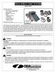
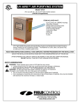
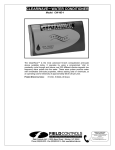
ELIMINATOR™ FOUNDATION
VENT FAN
Model: EL-1 and EL-1R
English......Page 1
Français....Page 5
Espanõl.....Page 8
This product is designed for ventilating or circulating air through crawl spaces of homes. By maintaining
constant air flow through the crawl space, problems such as fungus growth, dry rot, and radon gas will be
reduced or eliminated. An integral temperature switch allows fan operation only at air temperature above
50°F.
EL-1 UNIT INCLUDES:
120 volt ELIMINATOR™ fan unit with integral temperature fan control and mounting hardware.
OPTIONAL CONTROL:
EDH Eliminator™ De-Humidistat: 120 volt De-Humidistat to allow operation of fan at a set humidity level of
the crawl space.
READ THESE INSTRUCTIONS CAREFULLY AND COMPLETELY BEFORE PROCEEDING WITH THE INSTALLATION.
This device MUST be installed by a qualified agency in accordance with the manufacturer's installation instructions. The definition of
a qualified agency is: any individual, firm, corporation or company which either in person or through a representative is engaged
in, and is responsible for, the installation and operation of HVAC appliances, who is experienced in such work, familiar with all the
precautions required, and has complied with all the requirements of the authority having jurisdiction.
Please retain these instructions after installation.
Installed By:
Phone:
www.fieldcontrols.com
Installation Date:
MOUNTING LOCATION AND MOUNTING REQUIREMENTS
1. Locate fan on crawl space vent areas that do not have good cross flow ventilation.
2. The ELIMINATORTM fan unit must be mounted onto an existing or new crawl space vent that has a grill
mesh construction. (see mounting instructions)
3. One unit is recommended per 1,000 square feet of crawl space. The actual total number of units will be
based on moisture removal requirements of the crawl space.
MOUNTING INSTRUCTIONS
1. Remove any manual covering door on the crawl space vent where the unit is to be installed.
(See Figure 1) If plastic automatic vents are used, remove the closure vanes before installing fan onto
vent. (See Figure 2)
2. Hold ELIMINATORTM unit against the vent. Mark and poke 4 holes through the backing screen. This is to
be done at the location where the slotted mounting holes and the vent grill mesh intersect. (See Figure 3)
3. Secure ELIMINATORTM to the grill mesh of the vent with the supplied mounting anchors. Insert the flat
edge of the mounting anchor through the slotted holes in the ELIMINATORTM mounting plate and hook
the grill mesh of the vent. Hold in place and install the supplied flat washer and hex nut. After all four (4)
mounting brackets are installed, tighten nuts. (See Figure 4)
Figure 1
Figure 2
Figure 3
Figure 4
page 2
ELECTRICAL DATA
VOLTS
AMPS
HZ
WATTS
RPM
THERMAL OR IMPEDANCE PROTECTION
120 VAC
.60
60
35
3000
YES
A permanent wiring method must be used for power connection. It is recommended that a minimum size of
14 AWG wire for electrical supply connections and wiring should be suitable for 60OC (180OF) temperature.
The ELIMINATOR™ should be wired with an over current protection device (fuse or circuit breaker) rated 15
amperes or less. Wiring method should be in accordance with the National Electrical Code and any local
code requirements.
WIRING (See Figures 5 & 6)
Figure 5
Figure 6
page 3
LIMITED WARRANTY
Field Controls, LLC (“Company”) warrants that its products shall be free from defects in material and workmanship
under normal use for the limited period indicated, from the date of manufacture, subject to the provisions 1-8 below.
Eighteen (18) months
All Field Controls Products (except for those listed below as 5 years or 90 days).
Five (5) years
Field Controls Direct Vent Systems (FDVS), Field Oil Vent Kits (FOVP), and ComboVents (CV).
Field Controls warrants that the products listed below shall be free from defects in material and workmanship under
normal use for the limited period indicated, from the date of purchase by the consumer, subject to the provisions
1-8 below.
Ninety (90) days
UV lamps/bulbs
Provisions:
1. During the limited warranty period, Company, or its authorized service representative, will repair or replace, at Company’s
option, without charge, a defective Product. Product that is repaired may be repaired with new or refurbished replacement
parts. Product that is replaced may be replaced with a new or refurbished product of the same or similar design. Company
will return repaired or replacement Product to customer in working condition. Labor charges are not covered as part of the
limited warranty.
2. With regard to UV lamps/bulbs, customer shall be required to include a "valid proof of purchase" (sales receipt) identifying
the Product purchased (Product model or accurate date code information) and the date the Product(s) was purchased.
3. Product whose warranty/quality stickers, Product serial number plates or electronic serial numbers have been removed,
altered or rendered illegible shall not be covered under the limited warranty.
4. Defective Product must be returned to Company, postage prepaid.
5. IN NO EVENT SHALL COMPANY BE LIABLE FOR ANY INDIRECT, SPECIAL, INCIDENTAL, CONSEQUENTIAL, OR SIMILAR
DAMAGES (INCLUDING, BUT NOT LIMITED TO, LOST PROFITS OR REVENUE, INABILITY TO USE PRODUCT, OR OTHER
ASSOCIATED EQUIPMENT, THE COST OF SUBSTITUTE EQUIPMENT, AND CLAIMS BY THIRD PARTIES) RESULTING FROM
THE USE OF PRODUCT. Some states do not allow the exclusion or limitation of incidental or consequential damages, so the
above limitation or exclusion may not apply to you.
6. THIS WARRANTY AND REMEDIES ARE EXCLUSIVE AND IN LIEU OF ALL OTHER WARRANTIES, REMEDIES AND
CONDITIONS, WHETHER ORAL, WRITTEN, EXPRESS, STATUTORY OR IMPLIED. TO THE EXTENT PERMITTED BY LAW,
COMPANY DISCLAIMS ALL IMPLIED AND STATUTORY WARRANTIES, INCLUDING WARRANTIES OF MERCHANTABILITY
AND FITNESS FOR A PARTICULAR PURPOSE.
7. Company makes no warranty of any kind in regard to other manufacturer’s products distributed by Company. Company will
pass on all warranties made by the manufacturer and where possible, will expedite the claim on behalf of the customer, but
ultimately, responsibility for disposition of the warranty claim lies with the manufacturer.
8. Product that has been subjected to misuse, accident, shipping or other physical damage, improper installation or application,
abnormal operation or handling, neglect, fire, water or other liquid intrusion are not covered by the warranty.
page 4
VENTILATEUR E’ÉVENT DE
FONDATION ELIMINATORTM
Modèle: EL-1
EMPLACEMENT ET EXIGENCES D’INSTALLATION
1. Placer le ventilateur sur un évent de vide sanitaire où la ventilation à flux transversal est mauvaise.
2. Le ventilateur ELIMINATOR™ doit être installé sur un évent de vide sanitaire à grille (voir les instructions
d’installation).
3. Il est recommandé d’utiliser une unité pour chaque 1,000 pi2 de vide sanitaire. Le nombre total d’unités
requises dépendra des exigences en matière de déshumidification dans le vide sanitaire.
INSTRUCTIONS D’INSTALLATION
1. Retirer tout couvercle bouchant l’évent de vide sanitaire où le ventilateur sera installé. (Voir Le Schéma
1) Si des évents automatiques en plastique sont utilisés, retirer les volets de fermeture avant d’installer le
ventilateur sur l’évent. (Voir Le Schéma 2)
2. Tenir l’unité ELIMINATOR™ contre l’évent. Marquer et percer quatre trous dans l’écran. Cette opération
doit être effectuée au point d’intersection entre les trous de montage et la grille de l’évent. (Voir Le
Schéma 3)
3. Fixer l’unité ELIMINATOR™ à la grille de l’évent au moyen des pièces d’ancrage incluses. Insérer le
bout plat de l’ancre de montage dans les trous de la plaque de montage de l’unité ELIMINATOR™ et
accrocher à la grille de l’évent. Tenir en place et installer la rondelle plate et l’écrou hexagonal (inclus).
Une fois que les quatre supports de montage sont installés, serrer les écrous. (Voir Le Schéma 4)
Schéma 1
Schéma 2
Schéma 3
Schéma 4
page 5
DONNÉES ÉLECTRIQUES
VOLTS
AMPS
HZ
WATTS
TRS/MIN
PROTECTION THERMIQUE OU À IMPÉDANCE
120 CA
.60
60
35
3000
OUI
Une méthode de câblage permanent doit être utilisée pour le raccordement électrique. Il est recommandé d’utiliser un
câble de calibre 14 AWG au moins pour les raccords électriques, et le câblage devrait convenir pour une température
de 60°C (180°F). L’appareil ELIMINATOR™ devrait être muni d’un dispositif de protection de surintensité (fusible ou
disjoncteur) classé à 15 A ou moins. La méthode de câblage doit être conforme au Code national de l’électricité ainsi
qu’à toute exigence locale.
CÂBLAGE (Voir Le Schémas 5 & 6)
Schéma 5
Schéma 6
page 6
GARANTIE LIMITÉE
Field Controls, LLC (la « Société ») garantit que ses produits sont exempts de défauts de pièces et de main-d’œuvre
lors d’une utilisation normale pendant la période limitée indiquée, à compter de la date de fabrication, sous réserve
des dispositions 1 à 8 ci-dessous.
Dix-huit (18) mois
Tous les produits Field Controls (à l’exception de ceux indiqués ci-dessous sous 5 ans ou 90 jours).
Cinq (5) ans
Systèmes à ventouse Field Controls (FDVS), nécessaires d’évacuation pour mazout Field (FOVP) et systèmes
ComboVent (CV).
Field Controls garantit que les produits indiqués ci-dessous sont exempts de défauts de pièces et de main-d’œuvre
lors d’une utilisation normale pendant la période limitée indiquée, à compter de la date d’achat par le
consommateur, sous réserve des dispositions 1 à 8 ci-dessous.
Quatre-vingt-dix (90) jours
Lampes/ampoules UV
Dispositions :
1. Durant la période de garantie limitée, la Société, ou son représentant de service après-vente agréé, réparera ou
remplacera, au choix de la Société, sans frais, un Produit défectueux. Un Produit qui est réparé peut être réparé
avec des pièces de rechange neuves ou remises à neuf. Un Produit qui est remplacé peut être remplacé par un
produit neuf ou remis à neuf identique ou similaire. La Société renverra le Produit réparé ou de rechange en état
de marche au client. Les frais de main-d'œuvre ne sont pas couverts dans le cadre de la garantie limitée.
2. Concernant les lampes/ampoules UV, il est demandé au client d’inclure une preuve d’achat valable (reçu de
vente) identifiant le Produit acheté (modèle de Produit ou code de date exact) et la date à laquelle le ou les
Produits ont été achetés.
3. Un Produit dont les autocollants de garantie/qualité, les plaques de numéro de série du Produit ou les numéros de
série électroniques ont été enlevés, altérés ou rendus illisibles n’est pas couvert aux termes de la garantie limitée.
4. Le Produit défectueux doit être renvoyé à la Société en port payé.
5. EN AUCUN CAS LA SOCIETE N’EST RESPONSABLE DE QUELCONQUES DOMMAGES INDIRECTS, SPECIAUX,
ACCESSOIRES, CONSECUTIFS OU SIMILAIRES (NOTAMMENT, MAIS SANS S’Y LIMITER, LES MANQUES A
GAGNER, LA PERTE DE JOUISSANCE DU PRODUIT OU D’AUTRE MATERIEL ASSOCIE, LE COUT DU MATERIEL
DE SUBSTITUTION ET LES RECLAMATIONS PAR DES TIERS) RESULTANT DE L’UTILISATION DU PRODUIT.
Certaines provinces n’autorisant pas l’exclusion ou la limitation des dommages accessoires ou consécutifs, les
limitations ou exclusions ci-dessus peuvent ne pas s’appliquer à vous.
6. LA PRESENTE GARANTIE ET LES REPARATIONS SONT EXCLUSIVES ET REMPLACENT TOUTES LES AUTRES
GARANTIES, REPARATIONS ET CONDITIONS, QU’ELLES SOIENT ORALES, ECRITES, EXPRESSES,
REGLEMENTAIRES OU IMPLICITES. DANS LA MESURE AUTORISEE PAR LA LOI, LA SOCIETE DECLINE TOUTES
LES GARANTIES IMPLICITES ET REGLEMENTAIRES, NOTAMMENT LES GARANTIES DE QUALITE MARCHANDE
ET D’ADAPTATION POUR UN USAGE PARTICULIER.
7. La Société n’offre aucune forme de garantie concernant les produits d’autres fabricants distribués par la Société.
La Société transmettra toutes les garanties offertes par le fabricant et, dans la mesure du possible, accélérera le
recours pour le compte du client, toutefois la responsabilité finale du traitement d’un recours en garantie relève du
fabricant.
8. Un Produit qui a fait l'objet d’un emploi abusif, accident, expédition ou autre dommage physique, d’une
installation ou application incorrecte, d’une utilisation ou manipulation anormale, de négligence, de feu, de
pénétration d’eau ou autre liquide n’est pas couvert par la garantie.
page 7
VENTILADOR PARA EL RESPIRADERO DE
CIMIENTOS ELIMINATOR™
Modelo: EL-1
LUGAR DE INSTALACIÓN Y REQUISITOS PARA LA INSTALACIÓN
1. Coloque el ventilador en las zonas de ventilación del espacio sanitario que no tengan una buena
ventilación de flujo transversal.
2. La unidad de ventilación ELIMINATOR™ se debe instalar sobre un respiradero en el espacio sanitario
existente o en una que tenga una construcción de rejilla (Ver instrucciones de montaje).
3. Se recomienda una unidad por cada 1,000 pies cuadrados de espacio sanitario. La cantidad total de
las unidades se basará en los requisitos de remoción de humedad del espacio sanitario.
Figura 1
Figura 2
page 8
INSTRUCCIONES DE MONTAJE
1. Saque toda puerta de cobertura manual en el respiradero del espacio sanitario en donde se instalará
la unidad. (Ver Figura 1) Si se usan respiraderos automáticos de plástico, saque las paletas de oclusión
antes de instalar el ventilador contra el respiradero. (Ver Figura 2)
2. Sostenga la unidad del ELIMINATOR™ contra el respiradero. Marque y perfore 4 orificios a través de la
red. Esto se debe hacer en el lugar endonde se entrecruzan los orificios ranurados para el montaje y la
malla de la rejilla de ventilación. (Ver Figura 3)
3. Asegure el ELIMINATOR™ contra la malla de rejilla de ventilación con as anclas de montaje que se
suministran. Introduzca el borde plano del ancla de montaje a través de los orificios ranurados en la
placa de montaje del ELIMINATOR™ y enganche la malla de la rejilla de ventilación. Sosténgalo en
su lugar e instale la arandela plana y la tuerca hexagonal que se suministran. Después de que se hayan
instalado los cuatro (4) soportes de montaje, apriete las tuercas. (Ver Figura 4)
Figura 3
Figura 4
page 9
DATOS ELÉCTRICOS
VOLTS
AMPS
HZ
WATTS
TRS/MIN
PROTECCIÓN TÉRMICA O A IMPEDANCIA
120 CA
.60
60
35
3000
SI
Se debe usar un método permanente de cableado para la conexión de la corriente. Se recomienda
un tamaño mínimo de cable de 14 AWG para las conexiones de suministro eléctrico y adecuado para
temperaturas de 60ºC (180ºF). El ELIMINATOR™ debe estar cableado con un dispositivo de protección
contra sobrecorriente (fusible o disyuntor) de capacidad nominal de 15 amperios o menos. El método de
cableado debe ser conforme con el Código Eléctrico Nacional y todo requisito de los códigos locales.
CABLEADO (Ver Figuras 5 & 6)
Figura 5
Figura 6
page 10
GARANTÍA LIMITADA
Field Controls, LLC (“la Empresa”), garantiza que sus productos no tendrán defectos de materiales ni de fabricación
bajo condiciones de uso normales por el período límite indicado, a partir de la fecha de fabricación, sujeto a las
disposiciones 1 a 8, a continuación.
Dieciocho (18) meses
Todos los productos de Field Controls (salvo aquellos para los cuales se indica 5 años o 90 días
a continuación).
Cinco (5) años
Sistemas de ventilación directa de Field Controls (FDVS, por sus siglas en inglés), juego de ventilación de
aceite de Field Controls (FOVP, por sus siglas en inglés) y sistemas ComboVent (CV).
Field Controls garantiza que los productos indicados a continuación no tendrán defectos de materiales ni de
fabricación bajo condiciones de uso normales, por el período límite indicado, a partir de la fecha de compra por
parte del cliente, sujeto a las disposiciones 1 a 8, a continuación.
Noventa (90) días
Lámparas/bombillas UV
Disposiciones:
1. Durante el período de garantía limitada, la Empresa a su discreción, o su representante de servicio técnico
autorizado, reparará o reemplazará un producto defectuoso, sin cargo. Puede que un producto destinado a
reparación se repare con repuestos nuevos o renovados. Puede que un producto destinado a reemplazo se
reemplace por un producto nuevo o renovado con el mismo diseño o uno similar. La Empresa devolverá al cliente
el producto reparado o reemplazado, en buenas condiciones de funcionamiento. Los cargos por mano de obra
no están incluidos como parte de la garantía limitada.
2. En cuanto a las lámparas/bombillas UV, se necesitará que el cliente incluya una “prueba válida de compra” (el
recibo de compra) que identifique el producto comprado (modelo del producto o información precisa del código
de la fecha) y la fecha en la cual se compró.
3. No se incluirán en la garantía limitada los productos cuyos autoadhesivos de garantía o calidad, placas de
número de serie del producto o números de serie electrónicos hayan sido quitados, alterados o sean ilegibles.
4. El producto defectuoso se debe devolver a la Empresa con franqueo prepagado.
5. EN NINGÚN CASO LA EMPRESA SERÁ RESPONSABLE DE NINGÚN DAÑO INDIRECTO, ESPECIAL,
CONTINGENTE O EMERGENTE, O DAÑOS SIMILARES (INCLUIDA, ENTRE OTRAS, LA PÉRDIDA DE
GANANCIAS O INGRESOS, LA INCAPACIDAD DE USAR EL PRODUCTO U OTRO EQUIPO ASOCIADO, EL
COSTO DE EQUIPOS SUSTITUTOS Y RECLAMOS DE TERCEROS), QUE SEA CONSECUENCIA DEL USO DEL
PRODUCTO. Algunos estados no permiten la exclusión o limitación de daños contingentes o emergentes, de
modo que es posible que la limitación o exclusión anterior no se aplique en su caso.
6. ESTA GARANTÍA Y LOS RECURSOS SON EXCLUYENTES Y REEMPLAZAN A TODAS LAS OTRAS GARANTÍAS,
RECURSOS Y CONDICIONES, YA SEAN ORALES, ESCRITOS, EXPRESOS, REGLAMENTARIOS O IMPLÍCITOS.
EN LA MEDIDA QUE LO PERMITA LA LEY, LA EMPRESA NIEGA TODA GARANTÍA IMPLÍCITA Y
REGLAMENTARIA, INCLUIDAS AQUELLAS GARANTÍAS DE COMERCIABILIDAD E IDONEIDAD PARA UN
PROPÓSITO EN PARTICULAR.
7. La Empresa no establece ninguna garantía de ningún tipo relacionada con otros productos del fabricante que
ésta distribuye. La Empresa traspasará todas las garantías establecidas por el fabricante y, donde sea posible,
acelerará el reclamo en nombre del cliente, pero el fabricante es en última instancia el responsable de la
tramitación del reclamo de la garantía.
8. La garantía no incluye productos que hayan sido sometidos a mal uso, accidentes, daños por efecto del
transporte u otros daños físicos, instalación o aplicación inadecuada, operación o manipulación anormal,
negligencia, fuego, o la intrusión de agua u otro líquido.
page 11
Phone: 252.522.3031 • Fax: 252.522.0214
www.fieldcontrols.com
© Field Controls, LLC P/N 46267300 Rev E 08/09