1
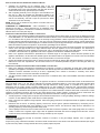
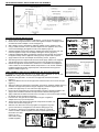
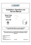
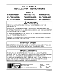
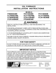
FIELD DIRECT VENT SYSTEM
Model: FDVS
ITEMS INCLUDED IN KIT:
FDVS Direct Vent Termination
*VRV-4 Vacuum Relief Valve
Backing Plate
Installation Instruction
Sheet
**Bagged Hardware
**Cover Ring
**Cover Sleeve
**Appliance Adapter
**Adapter Clamp
*Not included in some models
**Included with FOVP (Flex Oil Vent Pipe) for some models
Patent
Pending
The Field Direct Vent System (FDVS) is a non-powered positive pressure side wall vent termination system for use only
with specifically listed oil fired appliances. The system provides an outlet for exhaust gases and an intake for combustion
air in a single concentric terminal. The FDVS termination is designed to direct the hot exhaust gases away from the
structure using the static pressure generated by a special oil burner. All of the internal parts in contact with the flue gases
are made from corrosion resistant 316L stainless steel. The FDVS, with its built-in combustion air tee, allows connecting
standard galvanized pipe from the FDVS termination to the air intake of a special oil burner or by use of a Field Controls
Airboot, depending on the model of the oil burner.
DO NOT DESTROY
THESE INSTRUCTIONS MUST REMAIN WITH EQUIPMENT
WARNING:
This system MUST be installed by a qualified agency in accordance with the manufacturer’s installation
instructions.
The definition of a qualified agency is: any individual, firm, corporation or company which either in person or through a
representative is engaged in, and is responsible for, the installation and operation of oil appliances, who is experienced in
such work, familiar with all the precautions required, and has complied with all the requirements of the authority having
jurisdiction.
WARNING:
• Read the installation instructions carefully and completely before proceeding with the installation.
• For continued safe operation, the appliance vent system combination is required to be inspected and maintained
annually by a qualified agency. Failure to properly maintain the appliance vent system combination can lead to
Death, Personal Injury and or Property Damage
WARNING:
1. Safety inspection of a venting system should be performed before and after installing a venting system on an existing
or new appliance. Procedures to follow are the latest version of those recommended by the National Fuel Gas Code,
ANSI Z223.1, UL-726, NFPA31, CSA B139, CSA B140.0.03 appliance manufacturer’s recommendations, or refer to
the General Installation Inspection section of this manual.
2. Plan the vent system layout before installation to avoid the possibility of accidental contact with concealed wiring or
plumbing inside walls.
INSTALLATION OF FDVS DIRECT VENT SYSTEM
INSTALLATION OF THE VENT TERMINATION
(c)
(a)
(b)
(e)
(c)
(c)
(g)
Diagram A
1.
2.
3.
4.
5.
Remove vent system components from box and inspect for damage. If the
carton has been crushed or mutilated, check components very carefully for
damage. DO NOT install if any damage is apparent.
Remove the combustion air tee assembly from the vent termination. Set the tee
aside for later use.
Refer to the appliance manufacturer’s specifications for vent termination location.
The location of the vent termination must be installed with the manufacturer's
recommendations, and/or local codes that are applicable. In the USA according to
the latest version of the National Fire Protection Association NFPA-31, National
Fuel Gas Code ANSI Z223.1. Where requirements for venting standards differ the
most stringent standard shall apply. In Canada according to the latest version of
CSA B140 and the CSA B139 Installation Code. Refer to the following
requirements or See Diagram A for typical locations.
a. The exit termination of mechanical draft systems shall not be less than 7'
above grade when located adjacent to public walkways.
b. A venting system shall terminate at least 3' above any forced air inlet located within 10'.
c. The venting system of other than a direct vent appliance shall terminate at least 4'
below, 4' horizontally from, or 1' above any door, window or gravity air inlet into the
building.
d. The vent termination of a direct vent appliance with an input of 50,000 BTU's per hour or
less, shall be located at least 9" from any opening through which vented gases could
enter the building. With input over 50,000 BTU's per hour, a 12" termination clearance
shall be required.
e. The vent termination point shall not be installed closer than 3' from an
inside corner of an L-shaped structure.
f. The vent termination should not be mounted directly above, or within 3'
horizontally from an oil tank vent or gas meter.
g. The bottom of the vent terminal shall be located at least 12" above
finished grade or expected snow line, which ever is greater.
After determining the location of the venting system termination (See Diagram
A), cut a hole in the wall sized according to “L” dimension in Table 1. (See
Figure 1) NOTE: Maximum wall thickness: 12”
Seal the back side of the base plate around the outer pipe of the vent
termination with a bead of high temperature silicone sealant. (See Figure 2)
Mount the vent termination through the wall, keeping the outer pipe centered
in the hole. (See Figure 1) Fasten the vent termination to the outside wall with
appropriate fasteners. Seal the edges of the vent termination base plate to
the wall with a high-temperature silicone sealant.
Figure 1 – End View
Model
FDVS-4, 4C
FDVS-5
FDVS-6
“L”
7-1/4”
8-1/4”
9-1/4”
Table 1
Figure 2 – Side View
6. Mount the backing plate over the outer pipe. Fasten the backing plate to the inside wall with appropriate fasteners. (See Figure 2)
DO NOT BLOCK the intake or exhaust openings, or the intake access panel on the vent termination body. Wood or vinyl siding should
be cut so that the unit mounts directly on the wallboard to provide a stable support. If the siding is greater than 1/2" thick use a spacer
plate or board behind the vent termination mounting plate. (See Figure 2)
Page 2
INSTALLATION OF THE VENT TERMINATION COMBUSTION AIR TEE
1. Assemble the combustion air tee assembly body to the vent
termination outer pipe, and rotate to the desired position. Attach the
tee assembly body to the vent termination outer pipe with at least 3
sheet metal screws evenly spaced apart (not included).
2. After completing assembly of the vent pipe to the termination inner
pipe (Fig. 4), apply the supplied high temperature sealant to the
cover pan around the inner pipe, around the joint between the collar
and the Tee assembly, and seal or tape the joint from the FDVS
Termination to the Tee assembly.
NOTE: The tee may be rotated into any position so that the collar is in a
convenient orientation.
CLEARANCE TO COMBUSTIBLES: FDVS Termination: 0", FOVP
Flexible Oil Vent Pipe: 1". These clearances are to maintained unless
superceded by the appliance manufacturer's installation instructions or by
Figure 3 – Top View
National and/or local codes (see Step 3).
CONNECTING THE VENT PIPE FROM THE FDVS TO THE APPLIANCE
1. The venting system should be installed and supported in accordance with the latest version in the USA of the National Fuel Gas
Code ANSI Z223.1, UL-726, National Fire Protection Association NFPA31, and in Canada CSA B140, CSA B139 Installation Code
or in accordance with any other local codes or the authority having jurisdiction. Where requirements for venting differ the most
stringent standard requirements shall apply. A vent pipe connector, designed for positive pressure venting, shall be supported for
the design and weight of the material employed, to maintain clearances, prevent physical damage and separation of joints. All joints
MUST be sealed, for positive vent pressure, to prevent flue gas leakage into the structure.
2. Route the vent pipe from the appliance to the vent termination using the minimum number of bends as possible. The last horizontal
section of the vent pipe should have a slight downward slope from the appliance to the vent termination. For clearances to
combustible materials and other installation requirements, refer to the National Fuel Gas Code ANSI Z223.1, UL-726, NFPA31,
CSA B140, CSA B139 and/or any applicable local codes or appliance manufacturer's installation instructions.
3. Refer to the appliance manufacturer’s specifications for maximum length of vent pipe run. Unless otherwise specified by the
appliance manufacturer, use the same size diameter pipe as the exhaust outlet on the appliance to connect to the vent termination
inlet. Use a reducer or increaser, if necessary, at the vent termination to connect the vent pipe.
4. Support the Flexible Oil Vent Pipe (FOVP) at regular intervals of maximum 36" spacing with appropriate strapping or hangers, per
National and local code requirements. Do not install screws into or otherwise penetrate any part of the vent pipe under any
circumstances.
CONNECTING THE COMBUSTION AIR INTAKE PIPE FROM THE FDVS TO THE APPLIANCE
1. Refer to the appliance manufacturer’s specifications for maximum run length of combustion air intake pipe. Unless otherwise
specified by the appliance manufacturer, use the same size diameter pipe from the FDVS terminal combustion air tee collar to the
appliance oil burner combustion air inlet (or Air boot, if applicable.) Use a reducer or increaser, if necessary at the burner
combustion air inlet to connect the combustion air intake pipe.
2. The VRV should be installed close to the air inlet of the burner. To install the VRV, refer to the Installation Instructions included with
the VRV.
GENERAL INSTALLATION INSPECTION
Recommended procedures for safety inspection of an appliance should be in accordance with the latest version of the National Fuel
Gas Code ANSI Z 223.1, UL 726, and the National Fire Protection Association NFPA 31 in the USA, CSA B140 and CSA B139
Installation Code in Canada. The following procedure will help evaluate the venting system. It is intended as a guide to aid in
determining that the venting system is properly installed and is in a safe condition for continuous use. This procedure should be
recognized as a generalized procedure which cannot anticipate all situations. Accordingly, in some cases, deviation from this procedure
may be necessary to determine safe operation of the equipment. If it is determined that a condition exists which could result in unsafe
operation, the appliance should be shut off and the owner advised of the unsafe condition. Corrections must be made before the
appliance is put into continuous operation. The following steps should be followed in making a safety inspection.
1. Visually inspect the venting system for proper size and determine that there is no flue gas spillage, blockage, restriction, leakage,
corrosion, or other deficiency which could cause an unsafe operation.
2. Place in operation the appliance being inspected. Follow the lighting instructions and adjust thermostat so appliance will operate
continuously.
3. Determine that the burner is operating properly and that the burner ignition operates satisfactorily by interrupting and reestablishing the electrical power of the appliance in any convenient manner. Test the burner safety device to determine if it is
operating properly by disconnecting the flame safety circuit.
4. Test for spillage at the burner inlet air location around the VRV after 5 minutes of operation. Use a draft gauge, flame of a match or
candle, or smoke from a cigarette, cigar or pipe. Shut off appliance thermostat and check for spillage around the VRV. If a flow
reversal is noticed, house depressurization is occurring and make up air is required.
MAINTENANCE
Inspect all vent connections annually for looseness, evidence of corrosion, or flue gas leakage. Replace, seal, or tighten pipe
connections if necessary.
As part of the yearly maintenance schedule, remove the Intake Access Panel on the exterior of the FDVS vent termination (See Figure
2) and remove any debris or foreign material. Be sure to properly replace the panel.
Page 3
FIELD CONTROLS DIRECT VENT SYSTEMS VENT PIPE ASSEMBLY
Figure 4
APPLIANCE ADAPTER INSTALLATION:
1. Apply a bead of sealant to appliance collar approx. 1” from end of collar (Figure 5).
2. Remove all oil and grease from the inside of the appliance adapter, and apply a bead
of sealant to inside of adapter ½” from end (Figure 5).
3. With a twisting motion, assemble the appliance adapter onto the appliance collar.
4. Using a mallet and block of wood, drive the adapter onto the appliance collar, using
care to avoid damaging the appliance collar or the adapter (Figure 6).
5. Assemble adapter clamp halves using the supplied 5/16” bolts and square nuts, and
install the appliance clamp onto the adapter and tighten securely (Figure 5).
6. Install the supplied self-drilling, self-tapping anchoring screws through the 4 holes in
the appliance clamp into the appliance collar (Figure 6). No pilot hole is required.
7.
8.
9.
Figure 5
Apply sealant to the end of the adapter and anchoring screws. (Figure 6).
After testing and burner adjustments have been made, apply sealant to the supplied
3/8” sampling port plug screw and install the screw in the sampling port (Figure 6).
Maintain the appliance manufacturer's clearances to combustibles. If the appliance
collar is within 18" of combustible material, wrap minimum 1-1/2" ceramic insulation
(installer-supplied) around the exposed portion of the termination inner pipe and
appliance adapter (Figure 10).
JOINT ASSEMBLY: VENT PIPE TO TERMINATION AND APPLIANCE ADAPTER
If necessary, the vent pipe may be cut to length with a hacksaw or cut off saw.
CAUTION: Use safety glasses and other appropriate safety gear.
1. Pull outer vent pipe back 1”-2” from inner vent pipe end and remove insulation
(Figure 7).
2. Slide Cover Sleeve onto end of vent pipe a few inches back from end of outer vent pipe
(Figure 7).
3. Slide Cover Ring over stop bead on termination inner pipe or appliance adapter (Figure 7).
4. Assemble inner pipe clamp halves using the supplied ¼” bolts and square nuts, and
position inner pipe clamp ¼” from end of inner pipe (Figure 7).
5. Remove all oil and grease from end of termination inner pipe or appliance adapter, and
apply a bead of sealant to between the stop bead and retainer bead (Figure 8).
6. Apply a thick bead of sealant to inside of inner vent pipe ½” from the end of pipe, working
the sealant into the corrugations (Figure 8).
7. Push the inner vent pipe onto the termination inner pipe or appliance
adapter all the way up to the stop bead.
8. Tighten the inner pipe clamp bolts until both clamp halves are within 1/8”
of each other at each end (Figure 9).
9. Slide the cover sleeve and cover ring together to engage the ring in the
groove of the sleeve, and tighten the cover sleeve clamp (Figure 10).
10. To maintain 1" clearance to combustibles, wrap minimum 1-1/2" thick
ceramic insulation (installer-supplied) around the exposed portion of the
termination inner pipe
(Figure 10), and
secure with foil tape
(installer supplied).
Figure 9
Page 4
Figure 10
Figure 6
Figure 7
Figure 8
P/N 46483500 Rev C 12/05