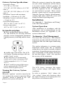
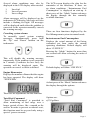
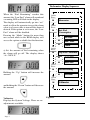
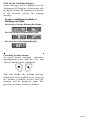
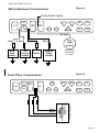
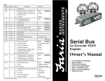
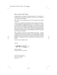
1
M
Serial Bus
for Navy Gateway
GW0016
Owners’s Manual
• Visual/Audible Alert messages
• Easy Installation
• Waterproof Connections
• Easy to read Digital displays
• Multiple Interfaces
IS0210
rev. A ecr#4821 Aug. 2004
Table of Contents
Quick Reference
turn system on/off
turn on instrument lighting
change lighting intensity
disable audible alarm in Normal Mode
change LCD display
reset Trip Fuel Consumed
Specifications
Turning the Gateway system ON/OFF
System description
Installation
System Operation
Tachometer/Fuel Management
canceling system alarms
engine hour meter
total fuel consumed
instantaneous fuel consumption
trip fuel consumed
clear trip fuel consumed
fuel remaining
fuel remaining alarm setting
voltmeter
Figure 1 (Tachometer Display Sequence)
LCD Alarm Condition displays
canceling system alarms
Faria® Bus Installation and Wiring Guide
installation
Gateway™ box
instruments
Appendix 1 Installation and Wiring
Figure 2 (Typical Power Connections)
Figure 3 (Typical Instrument Connections)
Figure 4 (Miscellaneous Connections)
Figure 5 (Fuel Flow Connections)
page 2
page 2
page 2
page 2
page 2
page 2
page 2
page 3
page 3
page 3
page 3
page 3
page 3
page 4
page 4
page 4
page 4
page 5
page 5
page 6
page 6
page 7
page 7
page 8
page 8
page 9
page 9
page 9
page 9
page 10
page 11
page 11
page 12
page 12
Navy Gateway (GW0016)
System Manual
intensity is reached no further changes can
be made by pressing the “DOWN” button.
The system consists of:
• One Gateway box to interface
with engine and external
senders and sensors.
• One 4” Tachometer with Fuel
Monitor
• Various 2” instruments,
including but not limited to
• Voltmeter
• Oil Pressure gauge
• Fuel gauge
• Engine Temperature gauge
• Transmission Temperature
Quick operation:
1. To turn on the system: Turn the ignition
key to “ON” position.
6. To disable the audible alarm in normal
mode: PUSH and HOLD both the
“UP” and the “DOWN” buttons on the
tachometer until the beeping stops.
7. To change the LCD display (engine
hour meter, system voltage):
a. Pressing the “Mode” button on the
tachometer will select the next LCD
display.
2. To turn off the system: Turn the ignition
key to “OFF” position.
3. To turn on instrument lighting: Turn
on the light switch on the vehicle instrument
panel.
4. To turn off instrument lighting:
Turn off the light switch on the vehicle
instrument panel.
b. Press the “Mode” button repeatedly
until desired function is displayed. The
gateway will switch to a screen displaying
the function data within 2 seconds after the
button is pressed.
5. To change the lighting intensity,
(requires the light switch be turned on):
a. Turn on the light switch as described in
item 3 above.
b. Pushing the “UP” button on the tachometer
will increase the intensity of the instrument
lighting. When maximum intensity is
reached no further changes can be effected
by pushing the “UP” button.
c. Pushing the “DOWN” button on the
tachometer will decrease the intensity of
the instrument lighting. When minimum
8. To reset Trip Fuel Consumed:
a. Use quick operation 7 above to show
“CLR TRP” on the LCD. Hold the “M”
button for more than one second while the
LCD displays “CLR TRP” to clear the trip
amount.
Page 2
Gateway System Specifications:
Operation voltage:
+12 V DC or +24 V DC
+12 V DC (10 V DC (Min.) to 16 V DC
(max.))
+24 V DC (20 V DC (Min.) to 32 V DC
(max.))
Maximum Current with maximum
backlight: < 1500 mA @ 12 V DC
Minimum Current at switch off status:
< 10 mA @ 12 V
Operational temperature:
-40˚ F to 185˚ F (-40˚ C to 85˚ C)
Storage temperature:
-40˚ F to 185˚ F (-40˚ C to 85˚ C)
System Description
♦ There are three push buttons (Mode,
UP, and DOWN) for selecting different
message screens, changing the instrument
lighting intensity, disabling audible alarm,
etc.
♦ Audible and visual alarms. The LCD
will display Warning messages while an
audible “beep” occurs.
♦ The Gateway is environmentally
sealed, and is water resistant per SAE
J1960 paragraphs 4.6.2, 4.7.1.2 and
4.8.1.2.
♦ Faria® serial bus gauges/light arrays
can be connected up to 120 feet (40
meters) from the gateway box.
Turning the Gateway System
ON/OFF
When the “ignition” switch is turned to the
“on” position, the system is turned on. When
“ignition” switch is turned to the “off”
position, the system will turn off.
Page 3
When the system is turned on, the pointer
on each of the instruments will be driven
to its most counter clockwise position, all
positions in warning arrays will light, and
all LCD segments on the 5” tachometer
are activated for 2 seconds. These actions
provide a quick check of system operation.
After this “boot-up” display, all instruments,
warning light arrays and LCD screen will
change to normal operating mode.
Installation
See Appendix 1: “Installation and Wiring”
at the end of this manual.
System Operation:
After installation in accordance with the
instructions and recommendations in the
Installation section (see Appendix 1), the
system is functional.
Tachometer / Fuel Management
The Serial Bus Tachometer / Fuel Monitor
instrument provides both the functions of a
tachometer and a fuel and engine monitoring
system.
The analog tachometer is a stepper motor
instrument which looks like a standard
analog device but which is actually a digital
instrument. On small pointer movements you
may occasionally see the pointer moving in
the one-third degree “steps” that represent
the accuracy of the instrument.
The LCD shows messages, like engine
hours, system voltage, and engine alarm
conditions.
In order to minimize “false” alarms, the
“low voltage” alarm only functions when
the engine is known to be running based on
the presence of tachometer data.
Several alarm conditions may also be
displayed in the LCD display when needed:
1
2
3
Low fuel
Low oil pressure
Low voltage
Alarm messages will be displayed on the
tachometer LCD display. Messages will also
include a flashing red light. All messages
will be displayed until either the problem is
corrected or the operator manually cancels
the warning message.
Canceling system alarms
To manually cancel system warning
messages, simultaneously press both
the “Up” and “Down” buttons on the
tachometer.
This will disable the warning message
temporarily. If the problem is not corrected
in 1 minute (5 minutes for low fuel), the
warning will be displayed again. The
operator can cancel as often as desired.
The LCD screen displays the data for the
remainder of the functions. If there are
no alarm conditions, “Instantaneous Fuel
Consumption” is displayed on start-up. A
short press of the “Mode” button advances
the display through the five normally
available functions.
There are four functions displayed by the
Fuel Management system in normal mode.
Instantaneous Fuel Consumption
Displays the actual amount of fuel being
consumed per hour under the current
operating conditions. Default display will
show “G/H XX.X.”
Pressing the “Mode” button for more than
one second will allow selecting the units of
measure.
Default display will show “G/H XX.X.”
Engine Hour meter
Displays the number of hours that the engine
has been operated. The display will show
“XXXX.XHr”.
A short press of the “Mode” button advances
the display through the options.
There are no adjustments for this function.
Total Fuel Consumed
“Total Fuel Consumed” is provided to
allow monitoring of fuel usage over a
longer period of time, like a month or the
season. In order to prevent accidental reset,
this function must be accessed only using a
special “power on mode.”
Options are:
a) US gallons
Page 4
b) Imperial gallons. Display will show
c) Liters. Display will show
Leaving the display in one of the items
above while the “Mode” button is pressed
and held for more than one second will save
the selected units.
Trip Fuel Consumed
Displays fuel consumed since last reset. This
function can be reset to zero before a trip to
show fuel consumed during the trip. Display
shows “TRPXXX.X.”
Pressing the “Mode” button for more
than one second while the display shows
“CLR TRP” will clear the trip amount and
set the menu back to the Trip Fuel Consumed
function.
A quick press of the “Mode” button will
skip this feature.
b) Adjust Trip Fuel Consumed, (fuel flow
calibration). Display will show “ADJ
TRP.”
Pressing the “Mode” button for more than
one second will cause the display to go into
the Trip Fuel Consumed adjustment menu.
The display will show “ADJXXX.X.”
Pressing the “Mode” for more than one
second will access the options that are
available for this function.
A short press of the “Mode” button advances
the display through the options. Display will
show “TRPXXX.X.”
Options are:
a) Clear Trip Fuel Consumed. Display will
show “CLR TRP.”
Page 5
Pressing and holding the “Up” button will
increase the amount and pressing and
holding the “Down” button will decrease
the amount.
Consumed” display) this display will show
the decreasing amount of fuel remaining.
Holding the “Mode” button for more than
one second while the display is showing
“ADJXXX.X” will set the amount in
the display “XXX.X” into the Trip Fuel
Consumed and return to the Trip Fuel
Consumed function.
The difference between the original and the
new amount of fuel will be used to change
the calibration of the instant and accumulated
fuel data.
This feature allows the fuel flow system to be
calibrated by accurately filling the fuel tank
at the beginning and end of a trip. When the
tank is refilled at the end of the trip, record
the exact amount of fuel placed in the tank.
Using the above method, adjust the amount
of fuel shown in the “ADJ TRP” to match the
amount of fuel recorded. Save the corrected
amount as described above. The “Trip Fuel
Consumed” in the previous menu can then
be cleared for reuse or left to continue to
accumulate fuel usage.
Fuel Remaining
Displays the fuel remaining based on a
manually entered amount of fuel minus the
amount of “Trip Fuel Consumed.”
Display shows “REMXXX.X.” This reading
is independent of the fuel “gauge” reading.
In normal use, the amount of fuel in the fuel
tank is adjusted manually when the fuel
tank is filled so that this display shows the
total amount of fuel in the tank. The “Trip
Fuel Consumed” is then reset to zero. As
fuel is used (displayed in the “Trip Fuel
Pressing the “Mode” for more than one second
will access the option available for this function.
a) Add to or remove gallons from the Fuel
Remaining. Display shows “R+-XXX.X.”
Holding the “Up” button will increase the
amount and holding the “Down” button will
decrease the amount.
Holding the “Mode” button for more than
one second will set the remaining fuel to the
value shown in the display and return the
menu to the Fuel Remaining alarm Setting
function.
This feature allows the operator to accurately
set the amount of fuel in the fuel tank when
adding fuel. The accuracy of this manually
entered value directly affects the Fuel
Remaining and Fuel Remaining Alarm
functions, and should be done carefully.
Fuel Remaining Alarm Setting
Displays the setting for the “Low Fuel”
alarm. The display shows “ALRXXX.X.”
Page 6
Tachometer Display Sequence
When the “Fuel Remaining” reaches this
amount, the “Low Fuel” alarm will sound and
a warning LED will flash in the display.
Quick
Press
The display will automatically go into “set”
mode to allow the operator to reset the alarm
value to a lower value to turn off the alarm if
desired. If the option is set to zero, the “Low
Fuel” alarm will be disabled.
Quick
Press
M
M
Pressing the “Mode” button for more than
one second while in the REM display will
access the option available for this function.
a) Set the amount of fuel remaining when
the alarm will go off. The display shows
“A+-XXX.X.”
Hourmeter
Inst. Fuel
Consumption
M
US GAL
M
IMP GAL
M
Liters
Quick
Press
M
Trip Fuel Consumed
M
CLR TRP
M
ADJ TRP
Quick
Press
Holding the “Up” button will increase the
amount
M
Fuel Remaining
M
ALARM
Quick
Press
M
and holding the “Down” button will decrease
the amount.
Voltmeter
Displays the System Voltage. There are no
adjustments available.
Page 7
Figure 1
Voltmeter
LCD Alarm Condition Displays.
Alarm messages will be displayed on the
Tachometer LCD display. All messages will
be displayed until the problem is corrected,
or the operator cancels the warning
message.
Severe conditions includes a
flashing red light.
Low Battery Voltage (Flashing Red Light)
Low Oil Pressure (Flashing Red Light)
Low Fuel Level (Flashing Red Light)
Canceling System Alarms
To cancel system warnings messages,
simultaneously press both the “Up” and
“Down” buttons on the tachometer.
This will disable the warning message
temporarily. If the problem is not corrected
in 1 minute (5 minutes for low fuel), the
warning will be displayed again. The
operator can cancel as often as desired.
Page 8
Faria® Serial Bus Installation and Wiring Guide
The system consists of:
• One Gateway box to interface with the engine and external senders and sensors.
• One 4” Tachometer with Fuel Monitor
• Various 2” instruments, including but not limited to
• Voltmeter
• Oil Pressure gauge
• Engine Temperature gauge
• Fuel Level gauge
• Transmission Temperature
Installation
Installation of the Fari® Serial Bus system is accomplished as follows:
Gateway Box
The Gateway™ box is the central unit of the system. As all of the senders and other
information source peripherals connect to the Gateway™, the Gateway™ box should be
mounted in a protected area in the best location to provide the maximum cabling benefit.
The Gateway™ box power cable must be installed to allow connection to “battery positive”
(always on), “battery negative” (ground), and a source of “switched power” which turns on
with the engine ignition switch (see Figure 2 and Table 1).
The “Faria® Bus” cable must be routed from the Gateway™ box to the instrument panel area
to connect the instruments to the data bus and instrument power (see Figure 3).
The remainder of the connections to the Gateway™ box are described below.
Instruments
The instruments are mounted using the provided back-clamps and mounting hardware.
Each instrument comes with a bus connection cable (12”). The main “Faria® Bus” cable
from the Gateway™ box is connected to the most convenient instrument using either of the
two four (4) pin connectors provided on the instrument case.
Each additional instrument is connected to the previous instrument using one of the 12” bus
connection cables. The cable may be connected to either of the two connectors provided on
the instrument case (see Figure 3).
Page 9
Appendix 1. Installation and Wiring
Table1
Connector Contacts
P1
2
P2
4
Pin
Pin Function
Wire Color
Not used
1
Battery Positive (always on)*
2
Ground
3
Switched Power from Ignition
Red
Purple
switch circuit
P3
4
4
Ground
Black
All
Faria® Bus Data and
N/A
Instrument Power
P4
2
Not Used
(PJ0015)
P5
3
Not Used
(PJ0016)
P6
3
Not Used
P7
3
Not Used
P8
PP
Not Used
P9
PP
Not Used
P10
PP
Not Used
P11
12
P12
12
P13
2
P14
6
P15
3
Navigation Lights Input
Dk. Blue
4
Tachometer Input
Grey
5
Fuel Flow Sensor Power
Black
6
Fuel Flow Input
White
7
Fuel Flow Ground
Shield w/ heat shrink
Not Used
1
Oil Pressure Sender
Lt. Blue
2
Fuel Tank Sender
Pink
5
Engine Temperature
6
Transmission Temperature
8
Not Used
*5 amp Fuse Recommended
Page 10
Faria Serial Bus Gateway
Typical Power Connections
Figure 2
P13
P7
P12
P15
P5
P4
P1
P11
P14
P10
P8
P6
P3
2
1
3
P2 4
Black
Red
Purple
-
SOP
GEN
+
Battery
Typical Instrument Connections
Figure 3
PJ0018
Note: To help reduce moisture
in the gauges be sure to install
plug PJ0018 in all open connectors.
P13
P14
Page 11
P7
P12
P15
P5
P4
P1
P3
P2
P11
P10
P8
P6
Faria Serial Bus Gateway
Figure 4
Miscellaneous Connections
Tachometer Input
6
7
5
8
P
4
9
1210
3P12
2
11
1
12
P13
P15
3 P 4
2
5
1 14 6
6
7
5
8
P
4
9
3 11 10
2
11
1
12
P7
P10
P8
P5
P6
P4
P1
P3
P2
Dk. Blue
Pink
Lt. Blue
Fuel
Tank
Sender
White
Oil
Pressure
Sender
Nav.
Light
Switch
White
Trans.
Sender
Instrument
Backlight
Control
Engine
Temp.
Sender
Figure 5
Fuel Flow Connections
P13
P15
P14
P9
P12
5
6
7
P7
P5
P4
P1
P3
P2
P11
P10
P8
Fuel Flow Transducer
Black
White
Shield w/Heat Shrink
P6
Page 12
Copyright 2004 by the Thomas G. Faria Corporation, Uncasville CT
No part of this publication may be reproduced in any form, in an electronic retrieval system or otherwise,
without the prior written permission of the company.
Faria® is the trademark of the Thomas G. Faria Corporation