1
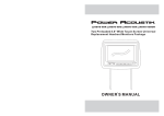
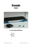
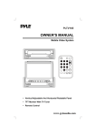
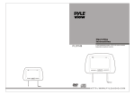
H-88BK
H-88BG
H-88GR
H-88GRDK
Two Preloaded 8.8" Wide Universal
Replacement Headrest Monitors Package
M
AUX
OWNER S MANUAL
SPECIFICATIONS
CONTENTS
,
Please read this User s Manual in detail and use the set properly.
CAUTION
3
INSTALLATION
5
NAME AND FUNCTION OF EACH PARTS
6
Unit
6
Remote Control
7
PICTURE CONTROL
8
CONNECTIONS
9
HOW TO OPERATION THE MONITOR
10
How To Swivel The Monitor
10
How To Watch The Monitor
10
SPECIFICATIONS
11
2
Power Requirements
DC 12V
Power Consumption
9W
Screen Size
8 . 8 T F T- L C D
Screen Format
16:9 Wide
Resolution Pixel
1440x234
A/V Inputs
3 AV Inputs(1 AV Input from front face)
Dimensions
11 . 6 ( L ) X 8 . 7 ( W ) X 4 . 7 ( H ) i n c h e s
Carrier frequency:
A CH:914MHz B CH:915MHz
LCD Panel Type
Active Matrix TFT
Compatible video standard
N T S C / PA L A u t o S e l e c t
Note : This equipment has been tested and found to comply with the limits for
a Class A digital device, pursuant to part 15 of the FCC Rules. These limits
are designed to provide reasonable protection against harmful interference
when the equipment is operated in a commercial environment.
This equipment generates, uses, and can radiate radio frequency energy and,
if not installed and used in accordance with the instruction manual, may cause
harmful interference to radio communications. Operation of this equipment in
a residential area is likely to cause harmful interference in which case the user
will be required to correct the interference at his own expense.
11
HOW TO OPERATE THE MONITOR
CAUTION
,
Please read and observe all warnings and instructions in this owner s manual
and those marked on the unit. Retain this booklet for future reference.
How to Swivel The Monitor
There are two kinds of alarm symbols as follows:
Yo u c a n a d j u s t t h e s w i v e l a n g l e a s s h o w n b e l o w.
The lightening flash with arrowhead symbol within an equilateral
triangle is intended to alert the user to the, presence of
dangerous voltage within the product s enclosure that may be
of sufficient magnitude to constitute a risk of electric shock to
WARNING people.
AUX
M
CAUTION
The exclamation point within an equilateral triangle is intended
to alert the user to the presence of important operating and
maintenance (servicing) instructions in the literature accompanying
the product.
Make this arrow to swivel the monitor
WARNING
P OWER
AV
MEN U
Do not mount the product where
it will obstruct the deployment of
the airbag or in an area where it
would affect the vehicular control.
Also be careful to avoid mounting
the product where it can become
hazardous during sudden stops or
in the event of an accident.
Installation of all TV monitors
must be out of the driver s
field of sight.
How to watch the monitor
1. Connect the monitor to the external devices.
2. Press the POWER button on either the remote control or the unit once to turn
the power on.
Press the same POWER button to turn the power off.
POWER
UNIT
Do not try and service these
products yourself, Seek only
a qualified service center or
factory service center.
Use extra caution with any liquids
in your car. If you or your child
Spills any liquid on these products,
pull your vehicle to the roadside
and turn the key off to disconnect
or wipe the products with a towel. Do not
operate the equipment until all liquids have
either evaporated or you have had the monitor
inspected at a service center by a qualified
technician, Severe harm or danger can
Occur.
Be careful not to drop or
apply under pressure to the
front panel of your video
monitor. If the screen cracks
due to misuse, your warranty
will be void!
Use only a damp cloth to clean
the screen and use only purified
water on the cloth. Wring out all
excess water prior to wiping the
screen. Do not use any cleaners
or chemicals to clean the screen.
In most cases a dry cloth will do!
REMOTE CONTROLLER
3. Turn on the external devices and view.
10
3
CAUTION
CONNECTIONS
CAUTION
Watching the monitor for an
extended period of time
with the engine turned off
may deplete the vehicle s
battery.
Quality installations are best
performed by qualified and
certifled installers.
M
M
AUX
AUX
This product is designed for
operation with a 12 Volt DC,
negative ground vehicle. It
is not suitable for operation
under other conditions or
voltages.
Don t touch the unit if there is
a flash of lightning. It may
receive an electric shock.
Do not cover heater ducts or vents.
This may cause a fire or an electric
shock.
Video
L - Audio - R
Monitor A Sub A/V Output
Monitor
Monitor
B
A
Headphone Headphone
Power
VC-90T
Check Point
1. The operating temperature of this product is limited to 14 F~140 F
(-10 C~60 C).
Your vehicle can reach temperatures up to 100 C in the summertime.
2. When your vehicle is extremely hot or cold you must allow time for your air
conditioner or heater to cool or heat the vehicle and for operating temperatures
to return to normal operating ranges. Your monitor will return to its normal
functions when these operating ranges are achieved.
3. Optimum picture quality is achieved when you are directly in front of the monitor
(+/-45 degrees).
4. If the buttons get stuck, please try to press the up of buttons, it will get back.
It won't impact using normal.
5. If you cann't find the files name in list when playing, please reset units or turn
off/on over again.
6. If the unit cann't be change mode when playing some special files which the
unit didn't support, please reset units or turn off/on over again.
AV1
Video
L - Audio - R
Video
AV2
DVD Input
L - Audio - R
DVD
Remote
Out
RF Wireless Stereo Headphone
(A CH:914MHz B CH:915MHz)
RF Wireless Stereo Headphone
(A CH:914MHz B CH:915MHz)
DVD/VCD/CD/CD-R/CD-RW/MP3
Reset
PLAY/PAUSE
4
9
PREV
NEXT
STOP
DVD
REMOTE
AV
EJECT
POWER
A/V INPUT
INSTALLATION
PICTURE CONTROL
Contrast/Brightness/Color
To adjust CONTRAST, BRIGHTNESS, COLOR press the MENU button until you
arrive at the screen for that item. Use the arrow buttons to adjust the value. Press
the MENU button to make another adjustment or leave the MENU system.
M
AUX
1. Bring up the on-screen function menu by pressing the MENU button on the unit
or the remote control.
2. Press the MENU button on the unit or the remote control of monitor until you see
the item you wish to adjust.
3. Use the arrow buttons to adjust the value.
4. Press the MENU button to make another adjustment or leave the MENU system.
Product installed
1. Remove the existing headrest from the seat.
CONTRAST
50
BRIGHTNESS
50
COLOR
50
2. Adjust the posts of the new headrest to fit the holes in the seat where the
headrest will be installed. The post can be moved together or apart
grasp one post in each hand, move the posts in opposing directions
(like they were walking) while pushing them toward each other or away
from each other.
3. Insert the cable in the proper hole. Insert the posts into the holes in the
seat and carefully work the headrest into position. Make sure the cable
is not pinched.
4. Run the cable down the seat and out to the location of the video source
unit (such as a DVD player).
5. See the picture on the right and you can adjust
the distance between the tubes to required
space(pole width adjustments 4 ~ 8.2 ) .
How to use the Adapter tubes
Since the spacing of the mounting holes
can vary on different veicles we supply
two adapter tubes. Use these tubes when
the headrest mounting holes in your seat
are too large for the posts of the headrest
monitor.
8
5
M
AUX
NAME AND FUNCTION OF EACH PART
NAME AND FUNCTION OF EACH PART
Remote Control
Unit
POWER
MUTE
SOURCE
POWER KEY
SUB-T
1
2
3
ANGLE
4
5
6
7
8
9
0
PROG
TITLE
ZOOM
MENU
M
SETUP
AUX
ENTER
GOTO
SLOW
AUDIO
1
2
3
4 5 6
8
P/N
7
- KEY
MENU KEY
8
DISPLAY
A-B
PBC
MENU
-
+
+
AV
+ KEY
-
MONITOR
AV1/AV2/Aux KEY
among
and
A/V Source Aux.
Interface Switch Function
HEADPHONE JACK
Headphone output
AUX Inputs
8 PIPE
Power Power ON/OFF
AV
Signal Select
Menu Press this button for OSD menu.
And select menu option.
Increase current option value.
+
Decrease current option value.
-
Adjustable steel Pipe
6
7