1
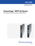
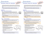
PowerCage™ MTP T AV and MTP R AV Board
Setup Guide
The Extron® PowerCage MTP T AV and
MTP R AV are twisted pair transmitters and
receivers in a modular board format for the
PowerCage 1600 modular enclosure. They
transmit or receive composite video or
S-video and audio over CAT 5-type cable.
Both boards can be used with any CAT 5, 5e, or 6 cable, or Extron
Enhanced Skew-Free™ A/V UTP cable for cable runs up to 1000 feet
(300 m). The boards mount in any of the 16 expansion slots at the rear of
the PowerCage 1600.
Refer to the PowerCage MTP T AV and MTP R AV User Guide and the
PowerCage 1600 Enclosure User Guide, available at www.extron.com.
PowerCage
MTP T AV
Y/VID
MTP R AV
R
L
AUDIO INPUT
2
1
SHARP GAIN
MONO
AUDIO OUTPUT
Y/VID
C
C
INPUT
OUTPUT
PowerCage
MTP R AV
NOTE: The hot-swappable, modular design allows for replacing or
upgrading boards in the field at any time, without having to
power down the system.
MTP T AV
Installation
1. Select an open slot at the rear, or take out a blank plate by loosening the two
screws (top and bottom), and lifting the blank away.
NOTE: If a board is already in the slot, loosen the screws and remove the board.
2. Remove the new board from the box,
holding the board by the frame.
3. Hold the board with the signal connectors
INPUT
age I
-SD
erC
Pow HD
3G
Y/VID
2
MODE
HD/SDI INPUT
1
MONO
AUDIO OUTPUT
Rx
Tx
1 2
Tx Rx
REMOTE
RS-232 ALARM
Tx Rx
RS-232
OVER FIBER
Align board and
slide into slot.
SHARP GAIN
age B
erC RG
Pow RX
4G
FOX
HD/SDI OUTPUTS
C
Tx
Rx
FOX
AUDIO
L
R
age B
erC RG
Pow RX
4G
Tx Rx
Tx
OUTPUT
Screws
(2 per board)
REMOTE
RS-232 ALARM
RS-232
OVER FIBER
V
-240 MA
100 5A
5. Tighten the screws to secure the board.
6. If applicable, repeat steps 1 through 5
Tx Rx
TED
LIS 3
1T2
E.
I.T.
0Hz
AUDIO
L
R
778
50/6
X.
1 2
Rx
FOX
US
C
N15
RGB
aligning that the two tabs on the lower
front end of the board with the matching
ports in the enclosure. Push the board
firmly into place.
age
erC AV
Pow R
MTP
Power
Supply
RGB
4. Carefully slide the board into the slot,
16 Available Single Board Slots or
8 Double Board Slots
OUTPUT
towards you and the MTP AV board name
and LED at the top, and align the top and
bottom grooves of the board with the slide
posts in the selected enclosure slot.
for any other modular boards.
NOTE: Cover all empty board slots; do not leave them open. Using a tool, securely
fasten the screws for boards and blank panels after initial installation and
subsequent removal and replacement of the boards.
7. If power has been removed, reconnect and power on the PowerCage. The LED on
the board lights green and the new board is auto-detected.
Y/VID
C
8. Following the image at right, connect input or output
device cables to the the two BNC connectors for S-video
signals or for composite video signals.
Continued on side 2.
S-video
Y/VID
C
OR
Composite
Video
1
PowerCage MTP T AV and MTP R AV Board Setup Guide, cont’d
9. Insert a 5-pole captive screw connector into the captive screw audio input or
output connector for balanced or unbalanced stereo audio input, or mono
output. Wire the connector as shown.
Tip
Sleeve
Balanced Stereo Input
Unbalanced Stereo Input
CAUTION
R
Do not tin the wires!
Tip
Ring
Sleeve (s)
Tip
Ring
L
Tip
Sleeve
Tip
Tip
Ring
Sleeve
Tip
Ring
NO Ground Here
For unbalanced audio, connect
Sleeve
the sleeve(s) to the ground contact.
Tip
DO NOT connect the sleeve(s) to NO Ground Here
the negative (-) contacts.
Unbalanced Mono Output
Balanced Mono Output
NOTE: These boards do not have a jumper to set for stereo audio output.
Audio output is always mono.
RJ-45
Connector
10.Either connect the output RJ-45 on the
Pins:
MTP T AV to an MTP receiver using CAT 5, 5e,
or 6 cable; or connect the input RJ-45 on the
MTP R AV board with an output cable to a suitable
MTP transmitter. Terminate the cable as shown on
the right, using the same standard
(T568A or T568B) at both ends.
12345678
11.Image sharpness and gain (MTP R AV only) can be
T568A
Wire color
Pin
T568B
Wire color
1
White-green
White-orange
2
Green
Orange
3
White-orange White-green
4
Blue
5
White-blue
White-blue
6
Orange
Green
Blue
7
White-brown
White-brown
8
Brown
Brown
Insert Twisted
Pair Wires
adjusted with the two front panel rotary encoders
for optimizing the image and signal quality.
View the image and adjust the either control for the best image quality.
PowerCage Front Panel
The following PowerCage enclosure front panel features are relevant to the
installation and operation of the MTP T AV and MTP R AV boards.
NOTE: The MTP T AV and MTP R AV boards are not configurable, and the
PowerCage Comm port feature does not work with the MTP boards.
a Power LED (slots 1-16) —
This LED lights to indicate that power
is applied to the selected board.
b Temperature LED — This LED
1
2
3
14
COMM
POWER
ALARM
lights if the temperature within
the PowerCage enclosure is high
(approximately 167 °F [75 °C]) and
equipment damage is imminent.
15
16
PSU
1
PSU
2
FAN
1
FAN
2
COMM
SELECT
TEMP
CONFIG
PowerCage 1600
1
2
For full installation and operating details of the PowerCage, refer to the
PowerCage 1600 Enclosure User Guide available at www.extron.com.
Extron USA - West
Headquarters
+800.633.9876
Inside USA / Canada Only
+1.714.491.1500
+1.714.491.1517 FAX
2
Extron USA - East
Extron Europe
Extron Asia
Extron Japan
Extron China
Extron Middle East
+800.633.9876
+800.3987.6673
+800.7339.8766
+81.3.3511.7655
+81.3.3511.7656 FAX
+400.883.1568
+971.4.2991800
+971.4.2991880 FAX
+1.919.863.1794
+1.919.863.1797 FAX
+31.33.453.4040
+31.33.453.4050 FAX
+65.6383.4400
+65.6383.4664 FAX
Inside USA / Canada Only
Inside Europe Only
Inside Asia Only
Inside China Only
+86.21.3760.1568
+86.21.3760.1566 FAX
© 2010 Extron Electronics. All rights reserved. www.extron.com
68-1643-50
Rev A
08 10