1
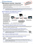
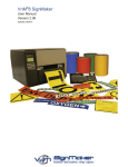
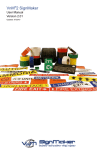
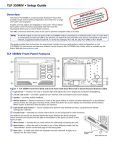
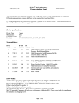
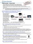
VNM 12 PS/PSR Power Supply • Installation Guide
The Extron VNM 12 PS and VNM 12 PSR power supplies provide an efficient
method to connect power to as many as twelve (12) VN-Matrix® 200/225 or
300/325 Series encoder/decoder units in 19 inch equipment racks. The single
rack space (1U) frame houses dual power supply modules (VNM 12 PS) or
three hot‑swappable power supply modules (VNM 12 PSR). A 12-way power
distribution panel, VNM 12 PSD, attaches to the rear of the equipment rack.
Cables are provided for connection between the panel and encoder/decoder
units.
VN-Matrix
Encoder/Decoders
The VNM 12 PS consists of two assemblies:
zz
zz
ES
RI IP
0 SE ER
X 20 I OV
RI DV
AT RGB/
-M
VN
-1
N
LA -2
N
LA US
AT
ST
VN
ES
RI IP
0 SE ER
X 20 I OV
RI DV
AT RGB/
-1
N
LA -2
N
LA US
AT
ST
VN
ES
RI IP
0 SE ER
X 20 I OV
RI DV
AT RGB/
-1
N
LA -2
N
LA US
AT
ST
VN
ES
RI IP
0 SE ER
X 20 I OV
RI DV
AT RGB/
-1
N
LA -2
N
LA US
AT
ST
-M
VN
the power supply unit (PSU) and,
the power supply distribution panel (PSD).
-1
N
LA -2
N
LA US
AT
ST
VN
-1
N
LA -2
N
LA US
AT
ST
VN
-M
-M
ES
RI IP
0 SE ER
X 20 I OV
RI DV
AT RGB/
-M
ES
RI IP
0 SE ER
X 20 I OV
RI DV
AT RGB/
-M
ES
RI IP
0 SE ER
X 20 I OV
RI DV
AT RGB/
-M
ES
RI
SE IP
-1
N
LA -2
N
LA US
AT
ST
The power supply distribution panel (VNM 12 PSD) is a 1U, 19 inch rack
mount unit that provides an interface from the power supply unit to the
VN-Matrix 200/225 or VN-Matrix 300/325 series encoder/decoders.
0 ER
X 20 I OV
RI DV
AT RGB/
-M
VN
-1
N
LA -2
N
LA US
AT
ST
VNM 12 PS
VNM 12 PSR (shown)
Features
zz
Compatible with VN-Matrix 200/225 or VN-Matrix 300/325 Series encoders and decoders.
zz
Simplified cabling — Two cables from power supply to distribution assembly.
zz
Hot-swappable triple supplies (VNM 12 PSR only) — Provide redundant power for up to 12 encoder/decoder units and
enable quick replacement with zero downtime.
Rack Mounting
VNM 12 PS and VNM 12 PSR
With built-in brackets and supplied hardware, both
units mount in a standard 19 inch rack in a 1U space.
VNM 12 PSD
This unit has adjustable rack ears. It may be mounted
directly behind the power supply if space is available.
Alternately, it can be mounted near the PSU and as far
to the rear of the rack as possible. Adjust the mounting
brackets to ensure the two main supply cables can be
connected to the power supply.
VNM 12 PS
or VNM 12 PSR
VNM 12 PSD
PSD to PSU Connection
Refer to the diagram at right to connect the
PSU to the PSD assembly.
1. Remove the terminal cover from the rear
of the VNM 12 PS or VNM 12 PSR unit.
2. Connect the cables from the PSU D-sub
connector to the corresponding power
supply terminals on the PSU.
3. Plug the D-sub connector into the PSU
rear panel as shown.
Red
Connect positive cables.
(Terminal is NOT color coded.)
Terminal Cover
a
Power Supply
Terminals
Rear Panel
D-sub Connector
c
PSU D-sub
Connector
CAUTION:
b
Black
Connect GND / RTN cables.
(Terminal is NOT color coded.)
VNM 12 PS
VNM 12 PSR
Rear
The rear panel terminals are not color coded. Connect the black wires to the terminal
labeled RTN or GND. Connect the red wires to the side that is not labeled.
1
VNM 12 PS/PSR Power Supply • Installation Guide (Continued)
4. Connect the two supply cables from the rear of the
VNM 12 PSD to the power supply terminals on the rear
of the PSU as shown.
Red
Connect positive cables.
(Terminal is NOT color coded.)
5. Replace the PSU terminal cover removed in step 1.
AC Power 3/4 Connector
(VNM 12 PSR only)
16 A Supply Required
Black
Connect GND / RTN cables.
3/4
(Terminal is NOT color coded.)
PSU D-sub
Connector
Supply Cables
1/2
VNM 12 PS
VNM 12 PSR
Rear
AC Power 1/2 Connector
(VNM 12 PS and VNM 12 PSR)
16 A Supply Required
VNM 12 PSD
Rear
PSD to VN-Matrix Connection
1. Using the supplied DC power cables, connect up to
12 VN-Matrix 200/225 or VN-Matrix 300/325 Series
encoder/decoder devices to the distribution assembly
as shown at right.
1
-I
DVI
IN
2
M
-I
DVI
T
CO
OU
PC
2. Connect AC power to AC connector 1/2,
(VNM 12 PS), or 1/2 and 3/4 (VNM 12 PSR).
M
2
CO
X
M
6A
1
M
-I
DVI
T
2
CO
V DC
12
G
RE
X
OU
V DC
12
G
RE
ITA
DIGDIO
AU
V DC
12
G
RE
X
6A
PC
T
-I
DVI
PC
MA
X
MA
-I
DVI
IN
T
H
RIP
PE
II
T
6A
AC 1/2
H
RIP
PE
II
I
L
ITA
DIGDIO
AU
OU
IN
VNM 12 PS
VNM 12 PSR
-I
DVI
CO
PE
I
L
ITA
DIGDIO
AU
OU
6A
1
-I
DVI
IN
T
PC
T
X
M
1
CO
OU
ITA
DIGDIO
AU
OU
V DC
12
G
RE
M
VN-Matrix 200/225 or
VN-Matrix 300/325 Series
Encoder/Decoder
II
T
X
2
OU
PC
OU
PC
IN
-I
DVI
CO
CO
H
RIP
PE
MA
IN
-I
DVI
H
RIP
IN
6A
6A
1
M
L
ITA
DIGDIO
AU
OU
V DC
12
G
RE
M
T
-I
DVI
II
I
L
CO
H
RIP
PE
2
M
L
ITA
DIGDIO
AU
T
X
I
MA
V DC
12
G
RE
CO
II
T
II
OU
V DC
12
G
RE
OU
MA
OU
2
-I
DVI
IN
I
IN
M
-I
DVI
T
H
MA
-I
DVI
I
IN
VNM 12 PS/PSR Power Supply Module
Replacement
6A
1
IN
L
X
6A
M
CO
PE
II
T
1
RIP
T
OU
PC
H
RIP
IN
M
CO
PE
OU
2
M
CO
OU
PC
IN
-I
DVI
-I
DVI
-I
DVI
T
MA
IN
1
IN
I
L
ITA
DIGDIO
AU
CO
M
RIP
PE
II
T
V DC
12
G
RE
CO
H
IN
OU
There are two LEDs on the front panel of each power
supply module. The AC Power LED indicates whether AC
power input is present on the module. The DC power LED
lights green during normal operation or red, accompanied
by an audible alarm, to indicate a failed or overloaded
supply.
2
M
CO
M
CO
I
L
ITA
DIGDIO
AU
MA
AC 3/4
DC Power Cables
(8 shown, 12 max.)
VNM 12 PSD
If a power supply module fails, it may be replaced without removing power.
NOTE: Failed power supply modules in the VNM 12 PS can be replaced without removing AC power. However, if a
module fails, depending upon how many VN-Matrix devices are connected, DC power output may be shut
down. A failed module is identified and replaced the same as the VNM 12 PSR using the procedure below.
To replace a module:
1. On the failed module, flip the front panel security latch up to release the module, then pull it from the frame.
2. Push the replacement supply into the frame making certain it is on the mounting rails.
3. Seat the supply by pressing it into the rear connector. Both the red AC and green DC indicators light when the power
supply is properly seated.
4. Flip the security latch down to secure the module.
Extron USA - West
Headquarters
Extron USA - East
Extron Europe
Extron Asia
Extron Japan
Extron China
Extron Middle East
+800.633.9876
+800.633.9876
+800.3987.6673
+800.7339.8766
Inside Asia Only
+81.3.3511.7655
+81.3.3511.7656 FAX
+400.883.1568
Inside Europe Only
+971.4.2991800
+971.4.2991880 FAX
+1.919.863.1794
+1.919.863.1797 FAX
+31.33.453.4040
+31.33.453.4050 FAX
+65.6383.4400
+65.6383.4664 FAX
Inside USA/Canada Only
+1.714.491.1500
+1.714.491.1517 FAX
2
Inside USA/Canada Only
Inside China Only
+86.21.3760.1568
+86.21.3760.1566 FAX
© 2011 Extron Electronics All rights reserved. www.extron.com
68-2002-01
Rev B
06 11