1
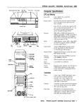
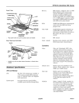
EPSON ActionNote 4000
Shadow RAM
System shadowed at F0000 to FFFF, 64KB;
VGA BIOS shadowed at E0000 to E8000,
32KB
Clock/
calendar
Real-time clock, calendar, and CMOS
RAM for configuration backed up by
built-in Dallas® DS 1287 or compatible
clock chip
Numeric
coprocessor
Socket for optional Cyrix® Cx 83S87
coprocessor
Controllers
rnemoty module or
numeric coprocessor
Diskette drive
Built-in controller for one external 3.5-inch
1.44MB diskette drive; supports 1.44MB
and 720KB diskette formats
Hard disk
Built-in controller for removable internal
hard disk drive
Video
Cirrus® GD6410B 16-bit VGA controller
fully backward compatible with CGA and
EGA; supports a standard monochrome
LCD with a maximum resolution of
640x480x64 shades of gray and an
external monitor with resolutions up to
800 x 600 x 16 colors; simultaneous LCD
and CRT operation
PCMCIA
Databook® DB86082 PCMCIA version 2.0
controller; Type II connector; supports
Type I and Type II memory and I/O cards
Speaker
Built-in ISA compatible speaker controller;
internal
Interfaces
Computer Specifications
External VGA
15-pin, D-sub, female connector for
external analog VGA or SVGA monitor
Parallel
Centronics® compatible, 25-pin, D-sub,
female connector; standard 8-bit parallel
Serial
RS-232C, programmable, asynchronous,
9-pin, D-sub, male connector
Pointing device
or external
keyboard
6-pin, mini-DIN connector for a PS/2®
compatible pointing device or keyboard;
keyboard supported directly, pointing
device requires adapter
AC adapter
DC input port for external AC adapter;
4-pin, mini-DIN connector
Main Unit
CPU
486SLC microprocessor; 33 MHz (and
simulated 8 MHz) clock speed; 1 MHz in
Suspend mode
Cache
1KB internal two-way set associative cache
System memory 4MB standard, 2MB soldered on main
system board and one 2MB memory
module; expandable to 8MB by replacing
the 2MB memory module with a 6MB
memory module; the first 640KB is
conventional memory and 128KB is used
for shadow RAM; the rest can be used as
extended or expanded memory
Input Devices
ROM BIOS
128KB on a single one-time programmable
ROM (includes system BIOS, VGA BIOS,
and the SETUP program)
Keyboard
79/80 (US) keys; embedded numeric
keypad and F11 and F12 keys; inverted T
cursor control key layout
Video RAM
256KB, 80ns video memory on main
system board; 256KB x 4 frame buffer
Trackball
Built-in, two-button trackball
7/27/93
ActionNote 4000-1
EPSON ActionNote 4000
Altitude
Mass Storage
Hard disk drive
One removable 2!4-inch internal hard disk
drive
Diskette drive
External, 3.5-inch diskette drive; 1.44MB
and 720KB diskette formats supported;
diskette drive connects to parallel port
VGA LCD
Monochrome
640 x 480 dots x 64 shades of gray,
7.5 inch, 0.23 mm dot pitch, high-contrast,
two-film; paper-white, backlit by one
cooled cathode fluorescent tube (CCFT);
continuous brightness and contrast
controls; power-saving feature; brightness
and contrast enhancement; contrast ratio
18:1
Caution
When traveling by airplane, bring the computer into the
passenger compartment as carry-on luggage to prevent it
from being stored in an unpressurized storage area.
Indicator Lights
The indicator lights provide information about the
computer’s operation.
Power-Indicates the computer is turned on.
Low battery-Flashes to indicate the battery capacity is
less than 20%.
Power Supply
AC adapter
Battery
+12 VDC (to computer), +18 VDC (to
battery charger), 3.0 A continuous AC
adapter with international voltage input,
47/63 Hz
Suspend mode-Indicates the computer is in Suspend
mode.
Hard disk drive-Indicates the computer is accessing
the hard disk drive.
Removable and rechargeable, internal
AE-size NiCad battery pack; 9-cell,
9.6 volt, 1.7AH, 16.3 W; typical 2% hour
battery life with SETUP Power
Management enabled
PCMCIA card slot--Indicates a PCMCIA card is in the
PCMCIA card slot and the computer is accessing the
card.
Num Lock-Indicates that Num Lock is set. This
activates the embedded numeric keypad on the
keyboard.
Caution
Use only the ActionNote 4000 AC adapter and battery with
the computer.
Caps Lock-Indicates that Caps Lock is set on the
keyboard.
Scroll Lock-Indicates that Scroll Lock is set on the
keyboard.
Physical Dimensions
Height
38 mm (1.5 in.)
Width
252 mm (10.0 in.)
Depth
Weight
(with battery
and hard disk
drive installed)
190 mm (7.6 in.)
1.75 kg (3.85 lb)
Operating: -61 to 3048 m
(-200 to 10,000 feet)
Non-operating: -61 to 9,090 m
(-200 to 30,000 feet)
Battery Alarm
When there are only 1 to 3 minutes of battery life remaining,
the computer beeps.
Options
80MB hard disk drive
Environmental Requirements
120MB hard disk drive
Temperature
6MB expansion memory module
Humidity
Operating: 5° to 40° C
(41° to 104°F)
Non-operating: -20° to 60° C
(-4° to 140° F)
Operating: 30% to 90%
(non-condensing)
Non-operating: 5% to 95%
(non-condensing)
Acoustical noise 35dB @ 1 meter
ActionNote 4000-2
NiCad battery pack
External keyboard
External keypad
Adapter for automobile cigarette lighter
2400/9600 baud fax/modem PCMCIA card
14,400/14,400 baud fax/modem PCMCIA card
7/27/93
EPSON ActionNote 4000
Main System Board Diagrams
System Board, Top Components and Connectors
J14
I
J7
J9
U5
J15
System Board, Bottom Components
7/27/93
ActionNote 4000-3
EPSON ActionNote 4000
System Board Components
Component
CPU (U1)
BTC-5001 (U2)
80C42/8742 (U4)
DS 1287 or compatible
RTC (U5)
TH6460 (U7)
DRAM (U13, U14,
U8, U9)
DB86082 (U10)
ACC 2036 (U12)
Description
486SLC/33 microprocessor: 1KB internal, two-way
set associative cache
BTC keyboard encoder&coder (70C40/77C82)
integrated, 8042 compatible, keyboard controller
Dallas DS 1287 or compatible RTC; includes
Lithium backup battery and RAM
Peripheral controller; provides one printer parallel
port, two 16450 UARTS, IDE HDD interface, FDC,
bus interface buffers
4MB standard memory, 2MB soldered on main
system board and one 2MB memory module;
expandable to 8MB by replacing the 2MB memory
module with a 8MB memory module (J5)
DataBook PCMCIA controller and driver interface
I module
System controller; provides AT bus control logic.
(U27, U28, U35)
ACC 2020 (U29)
AM27C010 (U30)
Buzzer (BZ1)
Power management controller
1024 Kb (128 Kb x 8) (OT) EPROM; VGA BIOS
ROM and Initialization BIOS ROM used during
power up; Databook Socket Services; supports
shadow RAM
Internal
External Connector Pin Assignments
Parallel Port Connector (J3)
pin 13
pin 1
pin 14
Parallel Port Connector Pin Assignments
F
Signal
Pin (Parallel)
1
/STROB
(Strobe)
2 I Data 0
3 I Data 1
Signal
(FDD)
Not connected
1 Index
1 Read data
12 1 Paper end
13 1 SLCT
1 Write data
I Write enable
Signal
Pin (Parallel)
14 /AUTOFD
15 /ERROR
16 1 /INlT
125 1 Ground
I
Signal
(FDD)
Reduce write
current
1
1 Head select
I Direction
I Ground
Serial Port Connector (J6)
System Board Connectors
Connector
I Description
Keyboard or mouse (J1)
1 6-pin, mini-DIN, female (back panel)
Cover switch (J2)
] P-pin header, mate
Parallel port, printer/external FDD (J3) 1 25-pin, D-shell, female (back panel)
PCMCIA (J4)
68-pin header, male
Memory module (J5)
44-pin header, female
Serial port, COM1 (J6)
9-pin, D-shell, male (back panel)
Keyboard ribbon cables (J7, J9)
Ribbon terminators, 8-pin and 16-pin,
respectively
IDE HDD (J8)
50-pin edge connector; female,
supports HDD
External CRT VGA (J11)
15-pin female, back panel
CCFT inverter, LCD backlight,
12-pin header, male
I
brightness/contrast (J12)
LCD panel (J13)
B-pin header, male
LED (J14)
10-pin header, male
Trackball (J15)
4-pin header, male
Power supply, DC-DC converter (J16) 22-pin connector, female; supplies
power from the power supply to the
main system board
Serial Port Connector Pin Assignments
Keyboard/Mouse Connector CJ1)
I
pin 5
pin 6
pin 3
pin 4
pin 1
pin 2
Keyboard/Mouse Connector Pin Assignments
Pin
1
2
3
ActionNote 4000-4
7/27/93
Signal
Mouse data
Keyboard data
Ground
Pin
4
5
6
Signal
+5 VCC
Clock, mouse
Clock, keyboard
I
EPSON ActionNote 4000
VGA Port Connector (J11)
PCMCIA Card Connector (J4)
pin 5
pin 1
pin 10
pin 6
pin 15
pin 11
VGA Port Connector Pin Assignments
AC-DC Power Connector (JP1)
pin 1
pin 2
pin 3
pin 4
AC-DC Power Connector Pin Assignments
Pin
1
2
3
4
Shielded
Signal
Ground
+12 VDC (A/D)
+18 VDC (B+)
1 Thermostat (T)
1 Frame ground
Memory Module Connector (J5)
IDE Hard Disk Drive Connector (J8)
pin 2
pin 50
pin 1
pin 49
pin 1 /
\ pin 43
Memory Module Connector Pin Assignments
IDE Hard Disk Drive Connector Pin Assignments
7/27/93
ActionNote 4000-5
EPSON ActionNote 4000
Internal Connector Pin Assignments
LED Connector (J14)
Trackball Connector (J15)
\
1 pin
pin 10
LED Connector Pin Assignments
This connector supports the built-in trackball pointing device.
Trackball Connector Pin Assignments
Pin
1
2
Signal
+5V (Vcc)
/RTSB
Pin
3
4
Signal
SINB
Ground
Internal Keyboard Connectors (J7 and J9)
Pin
1
2
3
4
15
Signal
Ground
HDDLED
CAPSLOCK
NUMLOCK
1 SCRLOCK
Pin
6
7
8
9
1 10
Signal
SR (PCMCIA)
/LOSPD
BALED
/BUSYLED
+5V
I
Cover Closed Switch Connector (12)
Cover Closed Switch Connector Pin Assignments
Pin
1
2
Internal Keyboard Connector Pin Assignments
Signal
Ground
Sleep
LCD Panel Connector (J13)
pin 8
pin 1
LCD Panel Connector Pin Assignments
DC-DC Power Connector (J16)
Pin
1
2
3
4
Signal
P4
P5
P6
P7
Pin
5
6
7
8
Signal
PO
P1
P2
P3
LCD (CCFT) Inverter Connector (J12)
pin 12
DC-DC Power Connector Pin Assignments
LCD (CCFT) Inverter Connector Pin Assignments
ActionNote 4000-6
7/27/93
pin 1
EPSON ActionNote 4000
DMA Assignments
Level
DMA0
DMA1
DMA2
DMA3
DMA4
DMA5
DMA6
DMA7
Assigned Device
Available
Available
FDD controller (8-bit)
Available
Cascade for CTRL 1
Available
Available
Available
Hard Disk Drive Types
*
Actual size when formatted may be slightly different than the size listed on the
drive label.
** Epson hard disk drive
Hardware Interrupts
IRQ No.
IRQ0
IRQ1
IRQ2
IRQ3
Function
System timer
Keyboard
cascade
COM2 (trackball)
IRQ5
IRQ6
IRQ7
IRQ8
IRQ9
IRQ10
IRQ11
IRQ12
IRQ13
IRQ14
IRQ15
Available
FDD controller
Parallel port LPT1
Clock/calendar
VGA
Available
Available
PS/2 compatible mouse
Resewed for numeric coprocessor
HDD controller
Available
System l/O Address Map
Hex Address
000-020
020-040
040-060
060-070
070-080
080-0A0
0A0-0C0
0C0-0F0
I Assigned Device
1 DMA controller 1
I Interrupt controller
Timer/counter
Keyboard controller
Real-time clock NM1 (non-maskable interrupt mask)
DMA page register
I Interrupt controller 2
I DMA controller 2
Programmable Timer/Counters
Power-On Diagnostics and Boot Errors
The computer’s ROM BIOS contains a series of diagnostic
programs, called the Power-On Diagnostics (POD) or
Power-On Self Test (POST). These programs check internal
devices, such as ROM, RAM, the timer, the keyboard
controller, and the hard disk drive, every time you turn on or
reset the computer.
When the POD tests detect an error, the computer displays a
message on the screen. (If the error occurs before the
computer initializes the video display, the computer beeps.)
If the error is serious, the computer cancels further checking
and stops system initialization. The computer locks up, and if
displayed, the error message remains on the screen.
The table below lists the error messages that may appear. The
solutions provided must be followed in order. If more than
one replacement module is specified, replace them in order,
one at a time.
Power-on Diagnostics Error Messages
Error No.
1
Message
CMOS Battery Has
Failed
2
CMOS Checksum Error
3
4
7/27/93
Explanation
Battery in DS 1287 or compatible
RTC that supports CMOS is low.
Replace DS 1287 or compatible RTC.
Checksum of CMOS is incorrect.
This can indicate that CMOS is
corrupted; it may be caused by a
weak battery. Check battery and
replace DS 1287 or compatible RTC
if necessary.
Interrupt channel #2 failed POD
routine.
Battery in DS 1287 or compattible
RTC that supports CMOS is low.
Replace DS 1287 or compatible RTC.
ActionNote 4000-7
EPSON ActionNote 4000
If you add the /A switch to the CARDTALK.SYS driver, the
computer also beeps when a PCMCIA card is inserted. The
table below lists the PCMCIA beep codes.
Power-on Diagnostics Error Messages (continued)
Error No.
5
Message
7
CMOS Display Type
Mismatch
10
Keyboard Error or No
Keyboatd Present
12
Memory Size Mismatch
13
FDD Controller Failure
FDD Drive Error
14
28
l
HDD Controller Failure
Unable to Initialize HDD
Drive
Disk Boot Failure
Check sum value is generated and
compared with CMOS values; if they
differ, an error occurs. Run SETUP.
Video type stored in CMOS does not
match type detected by BIOS. Run
SETUP.
BIOS encountered timing problem
with keyboard. Run SETUP and set
Halt On option to No Error. Replace
keyboard BIOS OTPROM.
Run SETUP. Replace memory
module, video controller (6410B),*
keyboard interpreter (BTC 5001),*
and/or main system board.
BIOS unable to communicate with
FDD controller. Check 6460. Run
SETUP.
BIOS unable to communicate with
FDD controller. Check cable
connection. Run SETUP and set
Parallel option to 1.44MB 3.5."
BIOS unable to communicate with
HDD. Run SETUP. Check
connection on main system board.
Replace hard disk drive, peripheral
controller (6460),* and/or main
system board.
Run SETUP.
PCMCIA Beep Codes
No. of Beeps
1 short
2 short
3 short
Description
The card is recognized.
The card Is not recognized. LAN cards require
drivers or enablers to be loaded; check the card
documentation for more information.
The card requires resources that are not available.
Installation/Support Tips
SETUP
The SETUP program is stored in the 128KB ROM BIOS. To
start the SETUP program, press the Delete key after the
system boots. The table below describes some SETUP options.
Selected SETUP Options
SETUP Option
Power Management
Parallel Port
BIOS reads diskette but cannot hoot
system. Run SETUP. Replace boot
diskette.
29
Memory Parity Error at
Parity error with DRAM on main
system board. Displays hexadecimal
address where error occurred.
Run diagnostics program.
Replace base memory DRAM
(1 MB x 4 bit, 60/70ns)* and/or main
system hoard.
30
Memory Verify Error at
Memory error with DRAM on main
system board. Displays hexadecimal
address where error occurred.
Run diagnostics program. Replace
memory module and/or main system
hoard.
Requites main system board replacement for service centers not authorized
to perform component level replacement.
Trackball
Description
Enables or disables a timeout period for the
computer and/or hard disk drive to conserve
battery power.
Defines the parallel port as the external diskette
drive port or the printer port.
Enables or disables the built-in trackball; to use a
mouse or other pointing device connected to the
EXT KB or COM 1 port, disable the built-in trackball. 1
Special Key Combinations
The following function and control key combinations can be
used in most DOS applications. However, some TSR
programs and other utilities that replace the normal DOS
keyboard interrupts may interfere with the operation of these
key combinations.
special Key Combinations
Key Combination
1 Function
Error Beep Code
If the POD tests detect an error but cannot display an error
message, the computer sounds the error beep code. An error
beep code is a distinct pattern of beeps that identifies the
error, such as one long beep and two short beeps. If there are
no errors, the computer beeps once before it loads the
operating system.
PCMCIA Installation/Setup
See the PCREADME.TXT file on the ActionNote 4000
Reference disk for information.
The table below describes the error beep code.
Error Beep Code
No. of Beeps
1 long, 2 short
Description
BIOS cannot initialize the video display; the computer is
1 unable to display additional information.
ActionNote 4000-8
I
7/27/93
EPSON ActionNote 4000
Information Reference List
Engineering Change Notices
None.
Technical Information Bulletins
None.
Product Support Bulletins
None.
Related Documentation
TM-AN4000
Epson ActionNote 4000 Service Manual
PL-AN4000
Epson ActionNote 4000 Parts Price List
SPKAN4000
Epson ActionNote 4000 Self Paced Kit
400221000
Epson ActionNote (4000) User’s Guide
400223600
Epson ActionNote (4000) Quick Reference
7/27/93
ActionNote 4000-9