1
Wireless N Gigabit Router
User’s Manual
Version: 1.0
ESR-9710 Wireless N Gigabit Router
Version 1.0
Table of Contents
1
INTRODUCTION .................................................................................................................... 5
1.1
1.2
1.3
1.4
1.5
1.6
1.7
2
UNDERSTANDING THE HARDWARE ................................................................................ 10
2.1
2.2
3
LOGGING IN ...............................................................................................................22
ADD A WIRELESS DEVICE ...........................................................................................22
USING THE PIN ..........................................................................................................23
USING THE PUSH BUTTON ..........................................................................................24
WIRELESS NETWORK SETUP WIZARD ........................................................................... 25
5.1
5.2
5.2.1
5.2.2
5.2.2.1
5.2.2.2
5.2.2.3
5.2.2.4
6
LOGGING IN ...............................................................................................................12
DHCP CONNECTION (DYNAMIC IP ADDRESS)..............................................................15
PPPOE (POINT-TO-POINT PROTOCOL OVER ETHERNET)..............................................16
PPTP (POINT-TO-POINT TUNNELING PROTOCOL) ........................................................17
L2TP (LAYER 2 TUNNELING PROTOCOL) .....................................................................18
STATIC IP ADDRESS CONFIGURATION ..........................................................................19
BIGPOND ...................................................................................................................21
WI-FI PROTECTED SETUP WIZARD.................................................................................. 22
4.1
4.2
4.2.1
4.2.2
5
HARDWARE INSTALLATION...........................................................................................10
IP ADDRESS CONFIGURATION .....................................................................................10
INTERNET CONNECTION WIZARD ................................................................................... 12
3.1
3.1.1
3.1.2
3.1.3
3.1.4
3.1.5
3.1.6
4
FEATURES & BENEFITS .................................................................................................5
PACKAGE CONTENTS....................................................................................................6
SAFETY GUIDELINES ....................................................................................................6
WIRELESS SOHO ROUTER DESCRIPTION .....................................................................7
SYSTEM REQUIREMENTS ..............................................................................................8
APPLICATIONS ..............................................................................................................8
NETWORK CONFIGURATION ..........................................................................................9
LOGGING IN ...............................................................................................................25
WIRELESS NETWORK SETUP ......................................................................................25
AUTOMATIC NETWORK SETUP .....................................................................................26
MANUAL NETWORK SETUP .........................................................................................26
WIRELESS SECURITY LEVEL: BEST (WPA2)...............................................................28
WIRELESS SECURITY LEVEL: BETTER (WPA) ............................................................29
WIRELESS SECURITY LEVEL: GOOD (WEP 64/128-BIT) .............................................30
WIRELESS SECURITY LEVEL: NONE (SECURITY DISABLED)...........................................31
ADVANCED WEB CONFIGURATION ................................................................................. 32
6.1
6.2
6.2.1
6.2.2
6.2.2.1
6.2.2.2
6.2.3
6.2.3.1
6.2.3.1.1
6.2.3.1.2
6.2.3.1.3
6.2.4
6.2.4.1
LOGGING IN ...............................................................................................................32
BASIC ........................................................................................................................33
WIZARD_WIRELESS ...................................................................................................33
NETWORK SETTINGS ..................................................................................................33
BRIDGE MODE ...........................................................................................................33
ROUTER MODE ..........................................................................................................34
WIRELESS SETTINGS..................................................................................................35
WIRELESS SECURITY MODE .......................................................................................36
WEP (WIRED EQUIVALENT PRIVACY) ..........................................................................36
WPA PERSONAL (WI-FI PROTECTED ACCESS) ............................................................37
WPA ENTERPRISE (WI-FI PROTECTED ACCESS & 802.1X)...........................................38
WAN SETTINGS .........................................................................................................40
STATIC IP ADDRESS CONFIGURATION ..........................................................................40
2
ESR-9710 Wireless N Gigabit Router
Version 1.0
Table of Contents
6.2.4.2
6.2.4.3
6.2.4.4
6.2.4.5
6.2.5
6.3
6.3.1
6.3.2
6.3.3
6.3.4
6.3.5
6.3.6
6.3.7
6.3.8
6.3.9
6.3.10
6.3.11
6.3.12
6.3.13
6.3.14
6.4
6.4.1
6.4.2
6.4.2.1
6.4.2.2
6.4.2.3
6.4.2.4
6.4.3
6.4.4
6.4.5
6.4.6
6.4.7
6.5
6.5.1
6.5.2
6.5.3
6.5.4
6.5.5
DHCP CONNECTION (DYNAMIC IP ADDRESS)..............................................................41
PPPOE (POINT-TO-POINT PROTOCOL OVER ETHERNET)..............................................42
PPTP (POINT-TO-POINT TUNNELING PROTOCOL) ........................................................44
L2TP (LAYER 2 TUNNELING PROTOCOL) .....................................................................45
BIGPOND ...................................................................................................................46
ADVANCED .................................................................................................................48
ADVANCED WIRELESS ................................................................................................48
VIRTUAL SERVER .......................................................................................................49
SPECIAL APPLICATIONS ..............................................................................................50
PORT FORWARDING ...................................................................................................51
STREAMENGINE .........................................................................................................51
ROUTING ...................................................................................................................54
ACCESS CONTROL .....................................................................................................54
WEB FILTER ...............................................................................................................57
MAC ADDRESS FILTER ...............................................................................................57
FIREWALL ..................................................................................................................58
INBOUND FILTER ........................................................................................................61
WISH........................................................................................................................62
WI-FI PROTECTED SETUP...........................................................................................63
ADVANCED NETWORK (UPNP, WAN PING…)..............................................................64
TOOLS .......................................................................................................................66
TIME ZONE SETTING...................................................................................................66
SYSTEM .....................................................................................................................67
SAVE CONFIGURATION TO A FILE .................................................................................67
RESTORE THE CONFIGURATION FROM A FILE ...............................................................68
RESTORE SETTINGS TO DEFAULT ................................................................................69
SYSTEM REBOOT .......................................................................................................69
FIRMWARE UPGRADE .................................................................................................70
SYSTEM LOGS ...........................................................................................................70
DYNAMIC DNS...........................................................................................................71
SYSTEM CHECK .........................................................................................................71
SCHEDULES ...............................................................................................................72
STATUS......................................................................................................................73
WIRELESS STATUS .....................................................................................................73
LOGS STATUS ............................................................................................................73
STATISTICS ................................................................................................................74
WISH SESSION STATUS .............................................................................................75
INTERNET SESSION STATUS ........................................................................................76
APPENDIX A – GLOSSARY......................................................................................................... 77
APPENDIX B – SPECIFICATIONS............................................................................................... 89
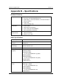
HARDWARE SUMMARY ..................................................................................................................89
RADIO SPECIFICATIONS.................................................................................................................89
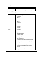
ROUTER AND GATEWAY .................................................................................................................89
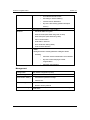
MANAGEMENT ..............................................................................................................................91
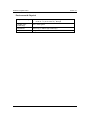
ENVIRONMENT & PHYSICAL ...........................................................................................................92
APPENDIX C – FCC INTERFERENCE STATEMENT ................................................................. 93
APPENDIX D – INDEX.................................................................................................................. 94
3
ESR-9710 Wireless N Gigabit Router
Version 1.0
Revision History
Version
Date
Notes
1.0
September 12, 2007
Initial Version
4
ESR-9710 Wireless N Gigabit Router
Version 1.0
1 Introduction
The Wireless-N Gigabit Router is a draft 802.11n compliant device that delivers up to 6x
faster speeds than 802.11g while staying backward compatible with 802.11g and 802.11b
devices.
It is not only a Wireless Access Point, which lets you connect to the network without
wires. There's also a built-in 4-port full-duplex 10/100/1000 Gigabit Switch to connect
your wired-Ethernet devices together. The Router function ties it all together and lets
your whole network share a high-speed cable or DSL Internet connection.
The Access Point built into the Router uses advanced MIMO (Multi-Input, Multi-Output)
technology to transmit multiple steams of data in a single wireless channel. The robust
signal travels farther, maintaining wireless connections up to 3 times farther than
standard 802.11g, eliminates dead spots and extends network range.
To protect the data and privacy, the Router can encode all wireless transmissions with
64/128-bit encryption. It can serve as your network's DHCP Server, has a powerful SPI
firewall to protect your PCs against intruders and most known Internet attacks, and
supports VPN pass-through. The router also provide easy configuration with the web
browser-based configuration utility.
The incredible speed and QoS function of 802.11n (draft2.0) Gigabit Router is ideal for
media-centric applications like streaming video, gaming, and VoIP telephony. It is
designed to run multiple media-intense data streams through the network at the same
time, with no degradation in performance.
This chapter describes the features & benefits, package contents, applications, and
network configuration.
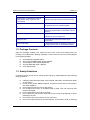
1.1 Features & Benefits
Features
High Speed Data Rate Up to 300Mbps
Benefits
Capable of handling heavy data payloads
such as MPEG video streaming
IEEE 802.11n draft Compliant and
backward compatible with 802.11b/g
Fully interoperable with IEEE 802.11b/g/n
devices
Four built-in 10/100/1000Mbps Gigabit
Switch Ports (Auto-Crossover)
Scalability, able to extend your network
Supports DNS/ DDNS
Lets users assign a fixed host and domain
name to a dynamic Internet IP address.
Shares single Internet account and provides a
type of firewall by hiding internal IP addresses
for keeping hacker out
Avoids unallowable users sharing bandwidth,
increases efficiency of the network
Avoids the attacks of Hackers or Viruses from
Internet
Supports NAT (Network Address
Translation)/NAPT
Hide SSID
Firewall supports Virtual Server
Mapping, DMZ, IP Filter, ICMP Blocking,
5
ESR-9710 Wireless N Gigabit Router
Version 1.0
SPI
Support 802.1x authenticator, 802.11i
(WPA/WPA2, AES), VPN pass-thru
mechanisms
Provide mutual authentication (Client and
dynamic encryption keys to enhance security
WDS (Wireless Distribution System)
Make wireless AP and Bridge mode
simultaneously as a wireless repeater
Universal Plug and Play (UPnP™)
Filter Scheduling
Works with most Internet gaming and instant
messaging applications for automatic Internet
access
The filter can be scheduled by days, hours or
minutes for easy management
Real time alert
The detection of a list for Hacker log-in
information
Web configuration
Helps administrators to remotely configure or
manage the Router via Telnet/Web-browser
1.2 Package Contents
Open the package carefully, and make sure that none of the items listed below are
missing. Do not discard the packing materials, in case of return; the unit must be shipped
in its original package.
h
h
h
h
h
One Wireless N Gigabit Router
One 12V/1.25A 90V~240V Power Adapter
Three 2dBi 2.4GHz Dipole Antennas
One CD-ROM with User’s Manual
Once Quick Guide
1.3 Safety Guidelines
In order to reduce the risk of fire, electric shock and injury, please adhere to the following
safety guidelines.
h
h
h
h
h
h
h
h
Carefully follow the instructions in this manual; also follow all instruction labels
on this device.
Except for the power adapter supplied, this device should not be connected to
any other adapters.
Do not spill liquid of any kind on this device.
Do not place the unit on an unstable stand or table. This unit may drop and
become damaged.
Do not expose this unit to direct sunlight.
Do not place any hot devices close to this unit, as they may degrade or cause
damage to the unit.
Do not place any heavy objects on top of this unit.
Do not use liquid cleaners or aerosol cleaners. Use a soft dry cloth for cleaning.
6
ESR-9710 Wireless N Gigabit Router
Version 1.0
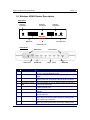
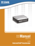
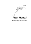
1.4 Wireless SOHO Router Description
Rear Panel
Antenna
Connector
Antenna
Connector
SMA
SMA
WAN
Antenna
Connector
SMA
DC JACK
LAN: 4*RJ45
10/100/1000M
WAN Port
DC Connector
LAN Ports (1-4)
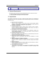
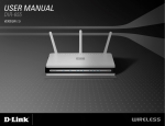
Front Panel
WPS Button
Power LED
Step
1
WLAN LED
Label
LAN Ports (1 – 4)
2
WAN Port
3
DC Connector
4
Antenna Connector
Connection / Activity
LED
WAN LED
WLAN LED
Power LED
Reset Button
WPS
Reset Button
LAN 1- 4 LED
WAN LED
Description
Use an Ethernet cable to connect each port to a computer
on your Local Area Network (LAN).
Use an Ethernet cable to connect this port to your WAN
router.
Use the power cable and connect the adapter to the power
socket on the wall, and the DC inlet into the DC connector.
Connect the three antennas to the SMA connectors.
This LED will light up once an Ethernet cable is connected
to one of the LAN ports.
This LED will light up once an Ethernet cable is connected
to WAN (Internet) port.
This LED will light up once the RF (wireless LAN) feature is
enabled
This LED will light up once the power cable is connected to
the DC connector.
Use this button to reset the device. You can restore the
device back to its factory default settings by holding down
on this button for 5 seconds.
WPS (Wireless Push Button) is used for WiFi Protected
Setup. By pressing this button, the security settings of the
7
ESR-9710 Wireless N Gigabit Router
Version 1.0
device will automatically synchronize with other wireless
devices on your network that support Wi-Fi Protected Setup.
1.5 System Requirements
The following are the minimum system requirements in order configure the device.
h PC/AT compatible computer with a Ethernet interface.
h Operating system that supports HTTP web-browser
1.6 Applications
The wireless LAN products are easy to install and highly efficient. The following list
describes some of the many applications made possible through the power and flexibility
of wireless LANs:
a) Difficult-to-wire environments
There are many situations where wires cannot be laid easily. Historic
buildings, older buildings, open areas and across busy streets make the
installation of LANs either impossible or very expensive.
b) Temporary workgroups
Consider situations in parks, athletic arenas, exhibition centers, disasterrecovery, temporary offices and construction sites where one wants a
temporary WLAN established and removed.
c) The ability to access real-time information
Doctors/nurses, point-of-sale employees, and warehouse workers can
access real-time information while dealing with patients, serving customers
and processing information.
d) Frequently changed environments
Show rooms, meeting rooms, retail stores, and manufacturing sites where
frequently rearrange the workplace.
e) Small Office and Home Office (SOHO) networks
SOHO users need a cost-effective, easy and quick installation of a small
network.
f) Wireless extensions to Ethernet networks
Network managers in dynamic environments can minimize the overhead
caused by moves, extensions to networks, and other changes with wireless
LANs.
g) Wired LAN backup
Network managers implement wireless LANs to provide backup for missioncritical applications running on wired networks.
h) Training/Educational facilities
Training sites at corporations and students at universities use wireless
connectivity to ease access to information, information exchanges, and
learning.
8
ESR-9710 Wireless N Gigabit Router
Version 1.0
1.7 Network Configuration
To better understand how the wireless LAN products work together to create a
wireless network, it might be helpful to depict a few of the possible wireless LAN PC
card network configurations. The wireless LAN products can be configured as:
a) Ad-hoc (or peer-to-peer) for departmental or SOHO LANs.
b) Infrastructure for enterprise LANs.
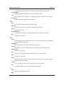
a) Ad-hoc (peer-to-peer) Mode
This is the simplest network configuration with several computers
equipped with the PC Cards that form a wireless network whenever they
are within range of one another. In ad-hoc mode, each client is peer-topeer, would only have access to the resources of the other client and
does not require an access point. This is the easiest and least expensive
way for the SOHO to set up a wireless network. The image below depicts
a network in ad-hoc mode.
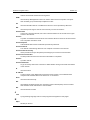
b) Infrastructure Mode
The infrastructure mode requires the use of an access point (AP). In this
mode, all wireless communication between two computers has to be via
the AP. It doesn’t matter if the AP is stand-alone or wired to an Ethernet
network. If used in stand-alone, the AP can extend the range of
independent wireless LANs by acting as a repeater, which effectively
doubles the distance between wireless stations. The image below
depicts a network in infrastructure mode.
9
ESR-9710 Wireless N Gigabit Router
Version 1.0
2 Understanding the Hardware
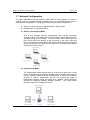
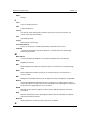
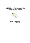
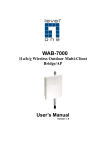
2.1 Hardware Installation
1. Place the unit in an appropriate location after conducting a site survey.
2. Plug one end of the Ethernet cable into the LAN port of the device and another end
into your PC/Notebook.
3. Plug one end of another Ethernet cable to WAN port of the device and the other end
into you cable/DSL modem (Internet)
4. Insert the DC-inlet of the power adapter into the port labeled “DC-IN” and the other
end into the power socket on the wall.
This diagram depicts the hardware configuration
PC
Ethernet
WLAN Router
AC/DC cable
Ethernet
Cable / DSL
Modem
Power Outlet
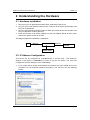
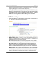
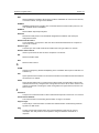
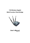
2.2 IP Address Configuration
This device can be configured as a Bridge/Router or Access Point. The default IP
address of the device is 192.168.1.2 In order to log into this device, you must first
configure the TCP/IP settings of your PC/Notebook.
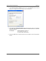
1. In the control panel, double click Network Connections and then double click on the
connection of your Network Interface Card (NIC). You will then see the following
screen.
10
ESR-9710 Wireless N Gigabit Router
Version 1.0
2. Select Internet Protocol (TCP/IP) and then click on the Properties button. This will
allow you to configure the TCP/IP settings of your PC/Notebook.
3. Select Use the following IP Address radio button and then enter the IP address
and subnet mask. Ensure that the IP address and subnet mask are on the same
subnet as the device.
For Example:
Device IP address: 192.168.1.2
PC IP address: 192.168.1.10
PC subnet mask: 255.255.255.0
4. Click on the OK button to close this window, and once again to close LAN properties
window.
11
ESR-9710 Wireless N Gigabit Router
Version 1.0
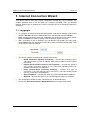
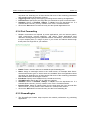
3 Internet Connection Wizard
This device offers a quick and simple configuration through the use of wizards. This
chapter describes how to use the wizard to configure the WAN, LAN, and wireless
settings. Please refer to Chapter 6 in order to configure the more advanced features of
the device.
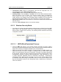
3.1 Logging In
To configure the device through the web-browser, enter the IP address of the device
(default: 192.168.1.2) into the address bar of the web-browser and press Enter.
Make sure that the device and your computers are configured on the same subnet.
Refer to Chapter 2 in order to configure the IP address of your computer.
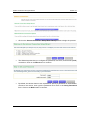
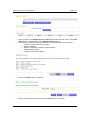
After connecting to the IP address, the web-browser will display the login page.
Select Admin from the drop-down list and then leave the password field blank. Click
on the Log In button to continue.
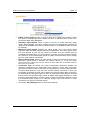
This device supports several types of WAN connections:
o DHCP Connection (Dynamic IP address) – Choose this connection type if
your ISP provides you the IP address. Most cable modems use this type of
connection.
o PPPoE (Poinit-to-Point Protocol over Ethernet) – Choose this option if
your internet connection requires a user name and password. Most DSL
modems use this type of connection.
o PPTP (Point-to-Point Tunneling Protocol) – Choose this type of
connection if your ISP requires you to use PPTP. Your ISP should provide
you with a user name and password.
o Static IP address – Choose this option if you have a dedicated IP address.
o BigPond – Choose this option if you use the BigPond service in Australia.
The configuration wizard for each connection type is described below.
Click on the Internet Connection Setup Wizard button to begin the process.
12
ESR-9710 Wireless N Gigabit Router
Version 1.0
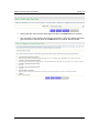
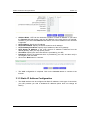
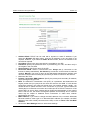
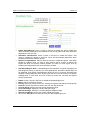
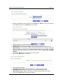
Click on the Internet Connection Setup Wizard Setup button to begin the process.
The Wizard requires that you configure the password, time zone, and Internet (WAN)
connection. Click on the Next button to continue.
By default, the device does not use a password. Specify a password for administrator
access to the device, then type the password once more in the Verify Password
field. Click on the Next button to continue.
13
ESR-9710 Wireless N Gigabit Router
Version 1.0
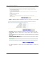
Select your time zone from the drop-down list Click on the Next button to continue.
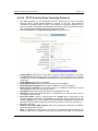
The next step in the wizard is the Internet Connection, select the WAN connection
type from the list, and then click on the Next button to continue with the wizard.
14
ESR-9710 Wireless N Gigabit Router
Version 1.0
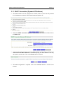
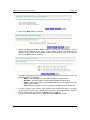
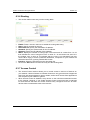
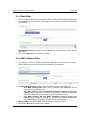
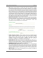
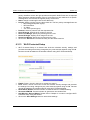
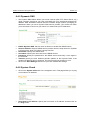
3.1.1 DHCP Connection (Dynamic IP Address)
The WAN interface can be configured as a DHCP Client in which the ISP provides
the IP address to the device. This is also known as Dynamic IP.
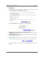
Select the DHCP Connection (Dynamic IP Address) radio button and then click on
the Next button.
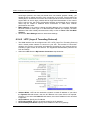
You have the option of cloning your PCs MAC address onto the device. Click on the
Clone Your PCs MAC Address to automatically copy the MAC address. You may
also specify a host name. Click on the Next button to continue.
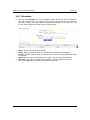
The WAN configuration is complete. Click on the Connect button to connect to the
Internet.
15
ESR-9710 Wireless N Gigabit Router
Version 1.0
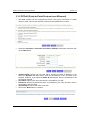
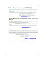
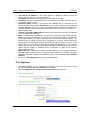
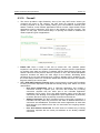
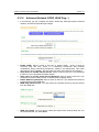
3.1.2 PPPoE (Point-to-Point Protocol over Ethernet)
The WAN interface can be configured as PPPoE. This type of connection is usually
used for a DSL service and requires a username and password to connect.
Select the Username / Password Connection (PPPoE) radio button and then click
on the Next button.
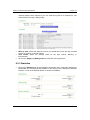
Address Mode: PPPoE can be used with a dynamic or static IP address. If you
select the Dynamic IP radio button, then the IIP address in the next field is not
required. However, if you select the Static IP radio button, then the IP address in the
next field is required.
User Name: Specify the user name which is provided by your ISP.
Password: Specify the password which is provided by your ISP, and then verify it
once again in the next field.
Service Name: Specify the name of the ISP.
Click on the Next button to continue.
16
ESR-9710 Wireless N Gigabit Router
Version 1.0
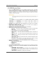
The WAN configuration is complete. Click on the Connect button to connect to the
Internet.
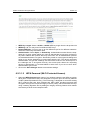
3.1.3 PPTP (Point-to-Point Tunneling Protocol)
The WAN interface can be configured as PPTP. PPTP (Point to Point Tunneling
Protocol) uses a virtual private network to connect to your ISP. This method of
connection is primarily used in Europe. This method of connection requires you to
enter a username and password (provided by your ISP) to gain access to the Internet.
The supported authentication protocols are PAP and CHAP.
Select the Username / Password Connection (PPTP) radio button and then click
on the Next button.
Address Mode: PPTP can be used with a dynamic or static IP address. If you select
the Dynamic IP radio button, then the IIP address in the next field is not required.
However, if you select the Static IP radio button, then the IP address in the next field
is required.
PPTP Address: Specify the IP address
PPTP Subnet Mask: Specify the subnet mask for the IP address.
PPTP Gateway IP Address: Specify the IP address of the PPTP gateway.
PPTP Server IP Address: If the PPTP Server’s IP address is different from the
default gateway, then you may specify it here.
17
ESR-9710 Wireless N Gigabit Router
Version 1.0
User Name: Specify the user name which is provided by your ISP.
Password: Specify the password which is provided by your ISP, and then verify it
once again in the next field.
Click on the Next button to continue.
The WAN configuration is complete. Click on the Connect button to connect to the
Internet.
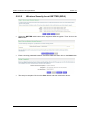
3.1.4 L2TP (Layer 2 Tunneling Protocol)
The WAN interface can be configured as L2TP. L2TP (Layer Two Tunneling Protocol)
uses a virtual private network to connect to your ISP. This method of connection
requires you to enter a user name and password (provided by your Internet Service
Provider) to gain access to the Internet. The supported authentication protocols are
PAP and CHAP.
Select the Username / Password Connection (L2TP) radio button and then click on
the Next button.
18
ESR-9710 Wireless N Gigabit Router
Version 1.0
Address Mode: L2TP can be used with a dynamic or static IP address. If you select
the Dynamic IP radio button, then the IIP address in the next field is not required.
However, if you select the Static IP radio button, then the IP address in the next field
is required.
L2TP Address: Specify the IP address
L2TP Subnet Mask: Specify the subnet mask for the IP address.
L2TP Gateway IP Address: Specify the IP address of the L2TP gateway.
L2TP Server IP Address: If the L2TP Server’s IP address is different from the
default gateway, then you may specify it here.
User Name: Specify the user name which is provided by your ISP.
Password: Specify the password which is provided by your ISP, and then verify it
once again in the next field.
Click on the Next button to continue.
The WAN configuration is complete. Click on the Connect button to connect to the
Internet.
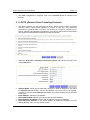
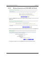
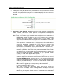
3.1.5 Static IP Address Configuration
The WAN interface can be configured as Static IP address. In this type of connection,
your ISP provides you with a dedicated IP address (which does not change as
DHCP).
19
ESR-9710 Wireless N Gigabit Router
Version 1.0
Select the Static IP Address Connection radio button and then click on the Next
button.
IP Address: Specify the IP address for this device, which is assigned by your ISP.
Subnet Mask: Specify the subnet mask for this IP address, which is assigned by
your ISP.
Gateway Address: Specify the IP address of the default gateway, which is assigned
by your ISP.
Primary / Secondary DNS Address: Specify the primary and secondary IP address,
which is assigned by your ISP.
The WAN configuration is complete. Click on the Connect button to connect to the
Internet.
20
ESR-9710 Wireless N Gigabit Router
Version 1.0
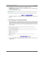
3.1.6 BigPond
The WAN interface can be configured as BigPong. This type of service is used
through Telstra BigPond Cable Broadband in Australia
Select the BigPond radio button and then click on the Next button.
User Name: Specify the user name which is provided by your ISP.
Password: Specify the password which is provided by your ISP, and then verify it
once again in the next field.
BingPond Server: Specify the server name or IP address as specified by your ISP.
Click on the Next button to continue.
The WAN configuration is complete. Click on the Connect button to connect to the
Internet.
21
ESR-9710 Wireless N Gigabit Router
Version 1.0
4 Wi-Fi Protected Setup Wizard
Wi-Fi Protected Setup is a feature that locks the wireless security settings and prevents
the settings from being changed by any new external registrar using its PIN. Devices can
still be added to the wireless network using Wi-Fi Protected Setup.
.Please refer to Chapter 6 in order to configure the more advanced features of the device
4.1 Logging In
To configure the device through the web-browser, enter the IP address of the device
(default: 192.168.1.2) into the address bar of the web-browser and press Enter.
Make sure that the device and your computers are configured on the same subnet.
Refer to Chapter 2 in order to configure the IP address of your computer.
After connecting to the IP address, the web-browser will display the login page.
Select Admin from the drop-down list and then leave the password field blank. Click
on the Log In button to continue.
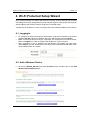
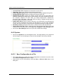
4.2 Add a Wireless Device
Click on the Wizard_Wireless link under the Basic menu, and then click on the Add
Wireless Device Wizard button.
22
ESR-9710 Wireless N Gigabit Router
Version 1.0
The wireless wizard will inform you that there are two major steps in the process.
o Select the configuration method for your wireless network
o Connect your wireless device
Click on the Next button to continue.
You may select from three available options:
o PIN: Select this radio button if your wireless device supports PIN
o Push Button: Select this radio button if your wireless device supports push
button.
o Manual: Select the radio button if you would like to setup your wireless
device manually. Refer to chapter 5 in order to manually configure the device.
The wizard will either display the wireless network settings to guide you through
manual configuration, prompt you to enter the PIN for the device, or ask you to press
the configuration button on the device. If the device supports Wi-Fi Protected Setup
and has a configuration button, you can add it to the network by pressing the
configuration button on the device and then the on the router within 60 seconds. The
status LED on the router will flash three times if the device has been successfully
added to the network.
There are several ways to add a wireless device to your network. Access to the
wireless network is controlled by a registrar. A registrar only allows devices onto the
wireless network if you have entered the PIN, or pressed a special Wi-Fi Protected
Setup button on the device. The router acts as a registrar for the network, although
other devices may act as a registrar as well.
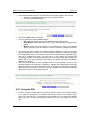
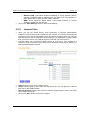
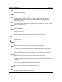
4.2.1 Using the PIN
A PIN is a unique number that can be used to add the router to an existing network
or to create a new network. The default PIN may be printed on the bottom of the
router. For extra security, a new PIN can be generated. You can restore the default
PIN at any time. Only the Administrator ("admin" account) can change or reset the
PIN.
23
ESR-9710 Wireless N Gigabit Router
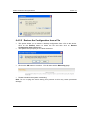
Select the PIN radio button and then click on the Next button.
Specify the PIN and then click on the Connect button.
The wireless device configuration is now complete.
Version 1.0
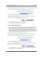
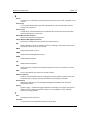
4.2.2 Using the Push Button
WPS is used for WiFi Protected Setup. By pressing the WPS button on the front
panel of the device, the security settings of the device will automatically synchronize
with other wireless devices on your network that support Wi-Fi Protected Setup
If the device supports Wi-Fi Protected Setup and has a configuration button, you can
add it to the network by pressing the configuration button on the device and then the
on the router within 60 seconds. The status LED on the router will flash three times if
the device has been successfully added to the network.
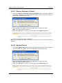
Select the Push Button radio button and then click on the Next button.
Press the WPS button on the device (which is located on the left side of the front
panel) and then click on the Next button.
24
ESR-9710 Wireless N Gigabit Router
Version 1.0
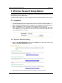
5 Wireless Network Setup Wizard
This wizard will guide you in the configuration of the wireless network settings such as
the SSID and security (WEP/WPA).
.Please refer to Chapter 6 in order to configure the more advanced features of the device
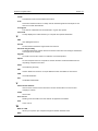
5.1 Logging In
To configure the device through the web-browser, enter the IP address of the device
(default: 192.168.1.2) into the address bar of the web-browser and press Enter.
Make sure that the device and your computers are configured on the same subnet.
Refer to Chapter 2 in order to configure the IP address of your computer.
After connecting to the IP address, the web-browser will display the login page.
Select Admin from the drop-down list and then leave the password field blank. Click
on the Log In button to continue.
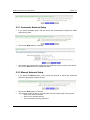
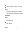
5.2 Wireless Network Setup
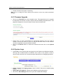
Click on the Wizard_Wireless link under the Basic menu, and then click on the
Wireless Network Setup Wizard button.
The wizard will inform you that there are two options: auto and manual.
25
ESR-9710 Wireless N Gigabit Router
Version 1.0
5.2.1 Automatic Network Setup
If you select the Auto option, then the device will automatically configure the SSID
and security mode.
Click on the Next button to continue.
The wizard has automatically configured the SSID and security mode for the device.
Click on the Save button to complete the setup.
5.2.2 Manual Network Setup
If you select the Manual option, then you will be required to specify the SSID and
select the appropriate network security.
Click on the Next button to continue.
The wireless wizard will inform you that there are three major steps in the process.
o Name your wireless network
o Secure your wireless network
o Set your wireless security password
26
ESR-9710 Wireless N Gigabit Router
Version 1.0
Click on the Next button to continue.
Specify the Wireless Network Name (SSID) for the device. The SSID is a unique
named shared amongst all the points of the wireless network. The SSID must be
identical on all points of the wireless network and cannot exceed 32 characters.
Click on the Next button to continue.
This step requires that you configure the security features based on your needs. The
following options are available.
o BEST – Select this option if your wireless adapters support WPA2
o BETTER – Select this option if your wireless adapters support WPA
o GOOD – Select this option if your wireless adapters do not support WPA, but
support WEP instead
o None: Select this option if you do not want to activate any security features.
In order to protect your network from hackers and unauthorized users, it is highly
recommended to secure the network using encryption and authentication. Select a
level of security and then click on the Next button to continue.
If you do not want to setup security, then select the NONE radio button.
27
ESR-9710 Wireless N Gigabit Router
5.2.2.1
Version 1.0
Wireless Security Level: BEST (WPA2)
Select the BEST radio button which supports WPA2 encryption. Then click on the
Next button.
Enter a security password between 2 and 20 characters then click on the Next button.
The setup is complete. Click on the Save button and then reboot the device.
28
ESR-9710 Wireless N Gigabit Router
5.2.2.2
Version 1.0
Wireless Security Level: BETTER (WPA)
Select the BETTER radio button which supports WPA encryption. Then click on the
Next button.
Enter a security password between 2 and 20 characters then click on the Next button.
The setup is complete. Click on the Save button and then reboot the device.
29
ESR-9710 Wireless N Gigabit Router
5.2.2.3
Version 1.0
Wireless Security Level: GOOD (WEP 64/128-bit)
Select the GOOD radio button which supports WEP encryption. Then click on the
Next button.
Enter a security password between 2 and 20 characters then click on the Next button.
The setup is complete. Click on the Save button and then reboot the device.
30
ESR-9710 Wireless N Gigabit Router
5.2.2.4
Version 1.0
Wireless Security Level: None (Security Disabled)
Select the NONE radio button if you do not want to activate any security features.
Then click on the Next button.
The setup is complete. Click on the Save button and then reboot the device.
31
ESR-9710 Wireless N Gigabit Router
Version 1.0
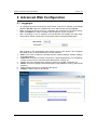
6 Advanced Web Configuration
6.1 Logging In
1.
2.
3.
4.
5.
6.
To configure the device through the web-browser, enter the IP address of the Bridge
(default: 192.168.1.2) into the address bar of the web-browser and press Enter.
Make sure that the device and your computers are configured on the same subnet.
Refer to Chapter 2 in order to configure the IP address of your computer.
After connecting to the IP address, the web-browser will display the login page.
Select Admin from the drop-down list and then leave the password field blank.
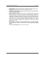
After logging in you will graphical user interface (GUI) of the device. The navigation
drop-down menu on left is divided into six main sections:
Basic: This menu includes the wireless wizard, network settings, wireless settings,
and WAN settings.
Advanced: This menu includes virtual server, special applications, port forwarding,
routing, access control, web filter, MAC address filter, firewall, etc.
Tools: This menu includes time, firmware, system log, DDNS, schedules, etc.
Status: This menu displays the wireless status, logs, statistics, routing, and internet
sessions.
Help: Displays the help for configuring the device.
Logout: Used to logout of the device.
32
ESR-9710 Wireless N Gigabit Router
Version 1.0
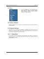
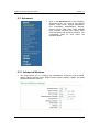
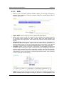
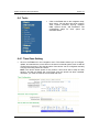
6.2 Basic
Click on the Basic link on the navigation dropdown menu. You will then see four options:
Wizard_Wireless, Network Settings, Wireless
Settings, and WAN Settings.
I
6.2.1 Wizard_Wireless
Refer to Chapters 4 and 5 in order to use the wireless wizard. The other options are
described below.
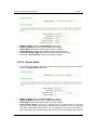
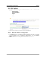
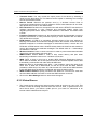
6.2.2 Network Settings
This device can be configured at a Router or a Bridge. Select Router mode if the
WAN port is connected to the Internet. Select Bridge if the device is connected to a
local network downstream from another router.
6.2.2.1 Bridge Mode
In this mode, the device functions as a bridge between the network on its WAN port
and the devices on its LAN port and those connected to it wirelessly. Select the
Bridge Mode radio button.
33
ESR-9710 Wireless N Gigabit Router
Version 1.0
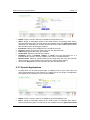
WAN Port Mode: Select the Bridge Mode radio button.
Router IP Address: Specify the IP address of this device.
Subnet Mask: Specify the subnet mask for the IP address.
Default Gateway: Specify the IP address of the upstream router.
Primary/Secondary DNS: Specify the IP address of the DNS server.
Click on the Save Changes button to store these settings.
6.2.2.2 Router Mode
In this mode, the device functions as a NAT router and is connected to the Internet.
Select the Router Mode radio button.
WAN Port Mode: Select the Router Mode radio button.
Router IP Address: Specify the IP address of this device
Subnet Mask: Specify the subnet mask for the IP address
Local Domain Name: This entry is optional. Enter a domain name for the local
network. LAN computers will assume this domain name when they get an address
from the router's built in DHCP server. So, for example, if you enter mynetwork.net
here, and you have a LAN side laptop with a name of chris, that laptop will be known
34
ESR-9710 Wireless N Gigabit Router
Version 1.0
as chris.mynetwork.net. Note, however, the entered domain name can be overridden
by the one obtained from the router's upstream DHCP server.
Enable DNS Relay: Place a check in this box to enable the DNS relay feature. When
DNS Relay is enabled, the router plays the role of a DNS server. DNS requests sent
to the router are forwarded to the ISP's DNS server. This provides a constant DNS
address that LAN computers can use, even when the router obtains a different DNS
server address from the ISP upon re-establishing the WAN connection. You should
disable DNS relay if you implement a LAN-side DNS server as a virtual server.
Click on the Save Changes button to store these settings.
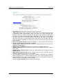
6.2.3 Wireless Settings
These options allow you to enable/disable the wireless interface, switch between the
11n, 11b/g and 11b radio band and channel frequency
Enable Wireless: Place a check in this box to enable the wireless interface, it is
enabled by default.
Wireless Network Name: The SSID is a unique named shared amongst all the
points of the wireless network. The SSID must be identical on all points of the
wireless network and cannot exceed 32 characters.
802.11 Mode: Select the IEEE 802.11 mode from the drop-down list. For example, if
you are sure that the wireless network will be using only IEEE 802.11g clients, then it
is recommended to select 802.11g only instead of 2.4 GHz B+G which will reduce
the performance of the wireless network. You may also select Mixed 802.11n,
802.11g and 802.11b. If all of the wireless devices you want to connect with this
router can connect in the same transmission mode, you can improve performance
slightly by choosing the appropriate "Only" mode. If you have some devices that use
a different transmission mode, choose the appropriate "Mixed" mode.
Wireless Channel: Select a channel from the drop-down list. The channels available
are based on the country’s regulation. A wireless network uses specific channels in
the wireless spectrum to handle communication between clients. Some channels in
your area may have interference from other electronic devices. Choose the clearest
channel to help optimize the performance and coverage of your wireless network.
35
ESR-9710 Wireless N Gigabit Router
Version 1.0
Transmission Rate: Select a transmission rate from the drop-down list. It is
recommended to use the Best (automatic) option.
Channel Width: Select a channel width from the drop-down list.
Visibility Status: Select Visible or Invisible. This is the SSID broadcast feature.
When this option is set to Visible, your wireless network name is broadcast to
anyone within the range of your signal. If you're not using encryption then they
could connect to your network. When Invisible mode is enabled, you must enter the
Wireless Network Name (SSID) on the client manually to connect to the network.
Show Active Clients: Click on this button to view a list of clients that are associated
with this device.
Click on the Save Changes button to store these settings.
6.2.3.1 Wireless Security Mode
To protect your privacy this mode supports several types of wireless security: WEP
WPA, WPA2, and WPA-Mixed. WEP is the original wireless encryption standard.
WPA provides a higher level of security. The following section describes the security
configuration in detail.
6.2.3.1.1
WEP (Wired Equivalent Privacy)
Select the WEP radio button if your wireless network uses WEP encryption. WEP is
an acronym for Wired Equivalent Privacy, and is a security protocol that provides the
same level of security for wireless networks as for a wired network.
WEP is not as secure as WPA encryption. To gain access to a WEP network, you
must know the key. The key is a string of characters that you create. When using
WEP, you must determine the level of encryption. The type of encryption determines
the key length. 128-bit encryption requires a longer key than 64-bit encryption. Keys
are defined by entering in a string in HEX (hexadecimal - using characters 0-9, A-F)
or ASCII (American Standard Code for Information Interchange - alphanumeric
characters) format. ASCII format is provided so you can enter a string that is easier
to remember. The ASCII string is converted to HEX for use over the network. Four
keys can be defined so that you can change keys easily. A default key is selected for
use on the network.
36
ESR-9710 Wireless N Gigabit Router
WEP Key Length: Select a 64-bit or 128-bit WEP key length from the drop-down list.
WEP Key 1-4: You may enter four different WEP keys.
Default WEP Key: You may use up to four different keys for four different networks.
Select the current key that will be used.
Authentication: Select Open, or Shared Key. Authentication method from the dropdown list. An open system allows any client to authenticate as long as it conforms to
any MAC address filter policies that may have been set. All authentication packets
are transmitted without encryption. Shared Key sends an unencrypted challenge text
string to any device attempting to communicate with the AP. The device requesting
authentication encrypts the challenge text and sends it back to the access point. If
the challenge text is encrypted correctly, the access point allows the requesting
device to authenticate. It is recommended to select Auto if you are not sure which
authentication type is used.
Click on the Save Changes button to store these settings.
6.2.3.1.2
Version 1.0
WPA Personal (Wi-Fi Protected Access)
Select the WPA-Personal radio button if your wireless network uses WPA encryption.
WPA (Wi-Fi Protected Access) was designed to improve upon the security features
of WEP (Wired Equivalent Privacy). The technology is designed to work with existing
Wi-Fi products that have been enabled with WEP. WPA provides improved data
encryption through the Temporal Integrity Protocol (TKIP), which scrambles the keys
using a hashing algorithm and by adding an integrity checking feature which makes
sure that keys haven’t been tampered with.
37
ESR-9710 Wireless N Gigabit Router
WPA Mode: Select the Auto WPA / WPA2 from the drop-down list.
Cipher Type: Select TKIP and AES as the cipher suite. The encryption algorithm
used to secure the data communication. TKIP. Use TKIP only. TKIP (Temporal Key
Integrity Protocol) provides per-packet key generation and is based on WEP. AES.
Use AES only. AES (Advanced Encryption Standard) is a very secure block based
encryption. Note that, if the bridge uses the AES option, the bridge can associate
with the access point only if the access point is also set to use only AES. TKIP and
AES. The bridge negotiates the cipher type with the access point, and uses AES
when available.
Group Key Update Interval: Specify the number of seconds before the group key
used for broadcast and multicast data is changed.
Pre-Shared Key: The key is entered as a pass-phrase of up to 63 alphanumeric
characters in ASCII (American Standard Code for Information Interchange) format at
both ends of the wireless connection. It cannot be shorter than eight characters,
although for proper security it needs to be of ample length and should not be a
commonly known phrase. This phrase is used to generate session keys that are
unique for each wireless client.
Click on the Save Changes button to store these settings.
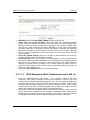
6.2.3.1.3
Version 1.0
WPA Enterprise (Wi-Fi Protected Access & 802.1x)
Select the WPA-Enterprise radio button if your wireless network uses WPA
encryption. WPA (Wi-Fi Protected Access) was designed to improve upon the
security features of WEP (Wired Equivalent Privacy). The technology is designed to
work with existing Wi-Fi products that have been enabled with WEP. WPA provides
improved data encryption through the Temporal Integrity Protocol (TKIP), which
scrambles the keys using a hashing algorithm and by adding an integrity checking
feature which makes sure that keys haven’t been tampered with.
This option works with a RADIUS Server to authenticate wireless clients. Wireless
clients should have established the necessary credentials before attempting to
authenticate to the Server through this Gateway. Furthermore, it may be necessary
to configure the RADIUS Server to allow this Gateway to authenticate users.
38
ESR-9710 Wireless N Gigabit Router
Version 1.0
WPA Mode: Select the WPA / WPA2 from the drop-down list.
Cipher Type: Select TKIP or AES as the cipher suite. The encryption algorithm used
to secure the data communication. TKIP. Use TKIP only. TKIP (Temporal Key
Integrity Protocol) provides per-packet key generation and is based on WEP. AES.
Use AES only. AES (Advanced Encryption Standard) is a very secure block based
encryption. Note that, if the bridge uses the AES option, the bridge can associate
with the access point only if the access point is also set to use only AES. TKIP and
AES. The bridge negotiates the cipher type with the access point, and uses AES
when available.
Group Key Update Interval: Specify the number of seconds before the group key
used for broadcast and multicast data is changed.
Authentication Timeout: Specify the number of minutes after which the client will be
required to re-authenticate.
RADIUS Server IP Address: Specify the IP address of the RADIUS server.
RADIUS Server Port: Specify the port number of the RADIUS server, the default
port is 1812.
RADIUS Server Shared Secret: Specify the pass-phrase that is matched on the
RADIUS Server.
MAC Address Authentication: Place a check in this box if you would like the user
to always authenticate using the same computer.
Optional Backup RADIUS server: This option enables configuration of an optional
second RADIUS server. A second RADIUS server can be used as backup for the
primary RADIUS server. The second RADIUS server is consulted only when the
primary server is not available or not responding.
Click on the Save Changes button to store these settings.
39
ESR-9710 Wireless N Gigabit Router
Version 1.0
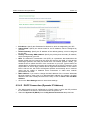
6.2.4 WAN Settings
The device offers several types of WAN connections in order to connect to the
Internet.
o Static IP Address
o Dynamic IP Address
o PPPoE
o PPTP
o L2TP
o BigPond
Select the type of Internet Connection from the drop-down list.
6.2.4.1 Static IP Address Configuration
The WAN interface can be configured as Static IP address. In this type of connection,
your ISP provides you with a dedicated IP address (which does not change as
DHCP).
Select the Static IP from the My Internet Connection drop-down list.
40
ESR-9710 Wireless N Gigabit Router
Version 1.0
IP Address: Specify the IP address for this device, which is assigned by your ISP.
Subnet Mask: Specify the subnet mask for this IP address, which is assigned by
your ISP.
Default Gateway: Specify the IP address of the default gateway, which is assigned
by your ISP.
Primary / Secondary DNS Address: Specify the primary and secondary IP address,
which is assigned by your ISP.
MTU: The Maximum Transmission Unit (MTU) is a parameter that determines the
largest packet size (in bytes) that the router will send to the WAN. If LAN devices
send larger packets, the router will break them into smaller packets. Ideally, you
should set this to match the MTU of the connection to your ISP. Typical values are
1500 bytes for an Ethernet connection and 1492 bytes for a PPPoE connection. If the
router's MTU is set too high, packets will be fragmented downstream. If the router's
MTU is set too low, the router will fragment packets unnecessarily and in extreme
cases may be unable to establish some connections. In either case, network
performance can suffer.
MAC Address: If you need to change the MAC address of the rounter's WAN-side
Ethernet interface, either type in an alternate MAC address (for example, the MAC
address of the router initially connected to the ISP) or click on Clone Your PCs MAC
Address.
Click on the Save Settings button to store these settings.
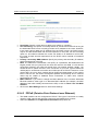
6.2.4.2 DHCP Connection (Dynamic IP Address)
The WAN interface can be configured as a DHCP Client in which the ISP provides
the IP address to the device. This is also known as Dynamic IP.
Select the Dynamic IP (DHCP) from the My Internet Connection drop-down list.
41
ESR-9710 Wireless N Gigabit Router
Version 1.0
Host Name: Specify a host name to define your system or connetion.
Use Unicasting: This option is normally turned off, and should remain off as long as
the WAN-side DHCP server correctly provides an IP address to the router. However,
if the router cannot obtain an IP address from the DHCP server, the DHCP server
may be one that works better with unicast responses. In this case, turn the unicasting
option on, and observe whether the router can obtain an IP address. In this mode,
the router accepts unicast responses from the DHCP server instead of broadcast
responses.
Primary / Secondary DNS Address: Specify the primary and secondary IP address,
which is assigned by your ISP.
MTU: The Maximum Transmission Unit (MTU) is a parameter that determines the
largest packet size (in bytes) that the router will send to the WAN. If LAN devices
send larger packets, the router will break them into smaller packets. Ideally, you
should set this to match the MTU of the connection to your ISP. Typical values are
1500 bytes for an Ethernet connection and 1492 bytes for a PPPoE connection. If the
router's MTU is set too high, packets will be fragmented downstream. If the router's
MTU is set too low, the router will fragment packets unnecessarily and in extreme
cases may be unable to establish some connections. In either case, network
performance can suffer.
MAC Address: If you need to change the MAC address of the rounter's WAN-side
Ethernet interface, either type in an alternate MAC address (for example, the MAC
address of the router initially connected to the ISP) or click on Clone Your PCs MAC
Address.
Click on the Save Settings button to store these settings.
6.2.4.3 PPPoE (Point-to-Point Protocol over Ethernet)
The WAN interface can be configured as PPPoE. This type of connection is usually
used for a DSL service and requires a username and password to connect.
Select the PPPoE from the My Internet Connection drop-down list.
42
ESR-9710 Wireless N Gigabit Router
Version 1.0
Address Mode: PPPoE can be used with a dynamic or static IP address. If you
select the Dynamic IP radio button, then the IIP address in the next field is not
required. However, if you select the Static IP radio button, then the IP address in the
next field is required.
User Name: Specify the user name which is provided by your ISP.
Password: Specify the password which is provided by your ISP, and then verify it
once again in the next field.
Service Name: Specify the name of the ISP.
Reconnect Mode: Select a reconnection time: Always on (A connection to the
Internet is always maintained), On demand (A connection to the Internet is made as
needed), Manual: You have to open up the Web-based management interface and
click the Connect button manually any time that you wish to connect to the Internet.
Maximum Idle Time:
Primary / Secondary DNS Address: Specify the primary and secondary IP address,
which is assigned by your ISP.
MTU: The Maximum Transmission Unit (MTU) is a parameter that determines the
largest packet size (in bytes) that the router will send to the WAN. If LAN devices
send larger packets, the router will break them into smaller packets. Ideally, you
should set this to match the MTU of the connection to your ISP. Typical values are
1500 bytes for an Ethernet connection and 1492 bytes for a PPPoE connection. If the
router's MTU is set too high, packets will be fragmented downstream. If the router's
MTU is set too low, the router will fragment packets unnecessarily and in extreme
cases may be unable to establish some connections. In either case, network
performance can suffer.
MAC Address: If you need to change the MAC address of the rounter's WAN-side
Ethernet interface, either type in an alternate MAC address (for example, the MAC
address of the router initially connected to the ISP) or click on Clone Your PCs MAC
Address.
Click on the Save Settings button to store these settings.
43
ESR-9710 Wireless N Gigabit Router
Version 1.0
6.2.4.4 PPTP (Point-to-Point Tunneling Protocol)
The WAN interface can be configured as PPTP. PPTP (Point to Point Tunneling
Protocol) uses a virtual private network to connect to your ISP. This method of
connection is primarily used in Europe. This method of connection requires you to
enter a username and password (provided by your ISP) to gain access to the Internet.
The supported authentication protocols are PAP and CHAP.
Select the PPTP from the My Internet Connection drop-down list.
Address Mode: PPTP can be used with a dynamic or static IP address. If you select
the Dynamic IP radio button, then the IIP address in the next field is not required.
However, if you select the Static IP radio button, then the IP address in the next field
is required.
PPTP Address: Specify the IP address
PPTP Subnet Mask: Specify the subnet mask for the IP address.
PPTP Gateway IP Address: Specify the IP address of the PPTP gateway.
PPTP Server IP Address: If the PPTP Server’s IP address is different from the
default gateway, then you may specify it here.
User Name: Specify the user name which is provided by your ISP.
Password: Specify the password which is provided by your ISP, and then verify it
once again in the next field.
Reconnect Mode: Select a reconnection time: Always on (A connection to the
Internet is always maintained), On demand (A connection to the Internet is made as
needed), Manual: You have to open up the Web-based management interface and
click the Connect button manually any time that you wish to connect to the Internet.
Maximum Idle Time:
Primary / Secondary DNS Address: Specify the primary and secondary IP address,
which is assigned by your ISP.
MTU: The Maximum Transmission Unit (MTU) is a parameter that determines the
largest packet size (in bytes) that the router will send to the WAN. If LAN devices
44
ESR-9710 Wireless N Gigabit Router
Version 1.0
send larger packets, the router will break them into smaller packets. Ideally, you
should set this to match the MTU of the connection to your ISP. Typical values are
1500 bytes for an Ethernet connection and 1492 bytes for a PPPoE connection. If the
router's MTU is set too high, packets will be fragmented downstream. If the router's
MTU is set too low, the router will fragment packets unnecessarily and in extreme
cases may be unable to establish some connections. In either case, network
performance can suffer.
MAC Address: If you need to change the MAC address of the rounter's WAN-side
Ethernet interface, either type in an alternate MAC address (for example, the MAC
address of the router initially connected to the ISP) or click on Clone Your PCs MAC
Address.
Click on the Save Settings button to store these settings.
6.2.4.5 L2TP (Layer 2 Tunneling Protocol)
The WAN interface can be configured as L2TP. L2TP (Layer Two Tunneling Protocol)
uses a virtual private network to connect to your ISP. This method of connection
requires you to enter a user name and password (provided by your Internet Service
Provider) to gain access to the Internet. The supported authentication protocols are
PAP and CHAP.
Select the L2TP from the My Internet Connection drop-down list.
Address Mode: L2TP can be used with a dynamic or static IP address. If you select
the Dynamic IP radio button, then the IIP address in the next field is not required.
However, if you select the Static IP radio button, then the IP address in the next field
is required.
L2TP Address: Specify the IP address
L2TP Subnet Mask: Specify the subnet mask for the IP address.
L2TP Gateway IP Address: Specify the IP address of the L2TP gateway.
45
ESR-9710 Wireless N Gigabit Router
Version 1.0
L2TP Server IP Address: If the L2TP Server’s IP address is different from the
default gateway, then you may specify it here.
User Name: Specify the user name which is provided by your ISP.
Password: Specify the password which is provided by your ISP, and then verify it
once again in the next field.
Reconnect Mode: Select a reconnection time: Always on (A connection to the
Internet is always maintained), On demand (A connection to the Internet is made as
needed), Manual: You have to open up the Web-based management interface and
click the Connect button manually any time that you wish to connect to the Internet.
Maximum Idle Time:
Primary / Secondary DNS Address: Specify the primary and secondary IP address,
which is assigned by your ISP.
MTU: The Maximum Transmission Unit (MTU) is a parameter that determines the
largest packet size (in bytes) that the router will send to the WAN. If LAN devices
send larger packets, the router will break them into smaller packets. Ideally, you
should set this to match the MTU of the connection to your ISP. Typical values are
1500 bytes for an Ethernet connection and 1492 bytes for a PPPoE connection. If the
router's MTU is set too high, packets will be fragmented downstream. If the router's
MTU is set too low, the router will fragment packets unnecessarily and in extreme
cases may be unable to establish some connections. In either case, network
performance can suffer.
MAC Address: If you need to change the MAC address of the rounter's WAN-side
Ethernet interface, either type in an alternate MAC address (for example, the MAC
address of the router initially connected to the ISP) or click on Clone Your PCs MAC
Address.
Click on the Save Settings button to store these settings.
6.2.5 BigPond
The WAN interface can be configured as BigPong. This type of service is used
through Telstra BigPond Cable Broadband in Australia
Select the BigPond from the My Internet Connection drop-down list.
46
ESR-9710 Wireless N Gigabit Router
Version 1.0
BingPond Server: Specify the server name or IP address as specified by your ISP.
User Name: Specify the user name which is provided by your ISP.
Password: Specify the password which is provided by your ISP, and then verify it
once again in the next field.
Primary / Secondary DNS Address: Specify the primary and secondary IP address,
which is assigned by your ISP.
MTU: The Maximum Transmission Unit (MTU) is a parameter that determines the
largest packet size (in bytes) that the router will send to the WAN. If LAN devices
send larger packets, the router will break them into smaller packets. Ideally, you
should set this to match the MTU of the connection to your ISP. Typical values are
1500 bytes for an Ethernet connection and 1492 bytes for a PPPoE connection. If the
router's MTU is set too high, packets will be fragmented downstream. If the router's
MTU is set too low, the router will fragment packets unnecessarily and in extreme
cases may be unable to establish some connections. In either case, network
performance can suffer.
MAC Address: If you need to change the MAC address of the rounter's WAN-side
Ethernet interface, either type in an alternate MAC address (for example, the MAC
address of the router initially connected to the ISP) or click on Clone Your PCs MAC
Address.
Click on the Save Settings button to store these settings.
47
ESR-9710 Wireless N Gigabit Router
Version 1.0
6.3 Advanced
Click on the Advanced link on the navigation
drop-down menu. You will then see thirteen
options: Virtual Server, Special Applications,
Port Forwarding, StreamEngine, Routing,
Access Control, Web Filter, MAC Address
Filter, Firewall, Inbound Filter, WISH, Wi-Fi
Protected Setup and Advanced Network. The
configuration steps for each option are
described below.
6.3.1 Advanced Wireless
This page allows you to configure the fragmentation threshold, RTS threshold,
beacon period, transmit power, DTIM interval, wireless isolation, WMM, and WDS
(wireless distribution system).
48
ESR-9710 Wireless N Gigabit Router
Version 1.0
Transmit Power: You may control the output power of the device by selecting a
value from the drop-down list. This feature can be helpful in restricting the coverage
area of the wireless network.
Beacon Period: Beacons are packets sent by a wireless Access Point to
synchronize wireless devices. Specify a Beacon Period value between 20 and 1000.
The default value is set to 100 milliseconds.
RTS Threshold: Packets over the specified size will use the RTS/CTS mechanism to
maintain performance in noisy networks and preventing hidden nodes from
degrading the performance. Specify a value between 1 and 65535. The default value
is 2346.
Fragment Threshold: Packets over the specified size will be fragmented in order to
improve performance on noisy networks. Specify a value between 256 and 65535.
The default value is 2346.
DTIM Interval: A DTIM is a countdown informing clients of the next window for
listening to broadcast and multicast messages. When the wireless Access Point has
buffered broadcast or multicast messages for associated clients, it sends the next
DTIM with a DTIM Interval value. Wireless clients detect the beacons and awaken to
receive the broadcast and multicast messages. The default value is 1. Valid settings
are between 1 and 255.
Wireless Isolation: Place a check in this box in order to prevent associated wireless
clients from communicating with each other.
WMM Enable: Enable WMM in order to help control latency and jitter when
transmitting multimedia content over a wireless connection.
WDS: Place a check in this box to enable WDS (Wireless Distribution System).
When WDS is enabled, this access point functions as a wireless repeater and is able
to wirelessly communicate with other APs via WDS links.
Note that WDS is incompatible with WPA -- both features cannot be used at the
same time. A WDS link is bidirectional; so this AP must know the MAC Address
(creates the WDS link) of the other AP, and the other AP must have a WDS link back
to this AP. Make sure the APs are configured with same channel number.
WDS AP MAC Address: Specify one-half of the WDS link. The other AP must also
have the MAC address of this AP to create the WDS link back to this AP.
Click on the Save Settings button to store these changes.
6.3.2 Virtual Server
The Virtual Server option gives Internet users access to services on your LAN. This
feature is useful for hosting online services such as FTP, Web, or game servers. For
each Virtual Server, you define a public port on your router for redirection to an
internal LAN IP Address and LAN port.
49
ESR-9710 Wireless N Gigabit Router
Version 1.0
Enable: Place a check in this box to enable the virtual server rule.
Name: Assign a meaningful name to the virtual server, for example Web Server.
Several well-known types of virtual server are available from the Application Name
drop-down list. Selecting one of these entries fills some of the remaining parameters
with standard values for that type of server.
IP Address: Specify the IP address for the virtual server entry.
Protocol: Specify a protocol or select one from the drop-down list.
Public Port: Specify the public port number.
Private Port: Specify the private port number.
Schedule: Select a schedule, Always, or Never from the drop-down list. If a
schedule does not exist, you may create it in the Tools > Schedule section.
Inbound Filter: Select an inbound filter from the drop-down list. If an inbound filter
does not exist, you may create it from Advanced > Inbound Filter section.
Click on the Save button to insert the entry into the Virtual Server list.
6.3.3 Special Applications
An application rule is used to open single or multiple ports on your router when the
router senses data sent to the Internet on a trigger port or port range. An application
rule applies to all computers on your internal network.
Enable: Place a check in this box to enable the special application rule.
Name: Assign a meaningful name to the virtual server, for example Web Server.
Several well-known types of virtual server are available from the Application Name
50
ESR-9710 Wireless N Gigabit Router
Version 1.0
drop-down list. Selecting one of these entries fills some of the remaining parameters
with standard values for that type of server.
Triggering Ports: Specify the outgoing port range that is used by the application.
Firewall Ports: Specify the prot range that you would like to open for Internet traffic.
Schedule: Select a schedule, Always, or Never from the drop-down list. If a
schedule does not exist, you may create it in the Tools > Schedule section.
Click on the Save button to insert the entry into the Special Applications list.
6.3.4 Port Forwarding
Multiple connections are required by some applications, such as internet games,
video conferencing, Internet telephony, and others. These applications have
difficulties working through NAT (Network Address Translation). This section is used
to open multiple ports or a range of ports in your router and redirect data through
those ports to a single PC on your network.
Enable: Place a check in this box to enable the port forwarding rule.
Name: Assign a meaningful name to the virtual server, for example Web Server.
Several well-known types of virtual server are available from the Application Name
drop-down list. Selecting one of these entries fills some of the remaining parameters
with standard values for that type of server.
IP Address: Specify the IP address for the virtual server entry.
TCP/UDP Ports: Specify the TCP or UDP port numbers.
Schedule: Select a schedule, Always, or Never from the drop-down list. If a
schedule does not exist, you may create it in the Tools > Schedule section.
Inbound Filter: Select an inbound filter from the drop-down list. If an inbound filter
does not exist, you may create it from Advanced > Inbound Filter section.
Click on the Save button to insert the entry into the Port Forwarding list.
6.3.5 StreamEngine
The StreamEngine feature helps improve the network performance by prioritizing
applications.
51
ESR-9710 Wireless N Gigabit Router
Version 1.0
Enable Traffic Shaping: Place a check in the box to enable traffic shaping. When
this option is enabled, the router restricts the flow of outbound traffic so as not to
exceed the WAN uplink bandwidth.
Automatic Uplink Speed. Place a check in this box to enable automatic uplink
speed. When enabled, this option causes the router to automatically measure the
useful uplink bandwidth each time the WAN interface is re-established (after a reboot,
for example).
Measured Uplink Speed: Displays the uplink speed. This is the uplink speed
measured when the WAN interface was last re-established. The value may be lower
than that reported by your ISP as it does not include all of the network protocol
overheads associated with your ISP's network. Typically, this figure will be between
87% and 91% of the stated uplink speed for xDSL connections and around 5 kbps
lower for cable network connections.
Manual Uplink Speed: Specify an uplink speed or select it from the drop-down list. If
Automatic Uplink Speed is disabled, this options allows you to set the uplink
speed manually. Uplink speed is the speed at which data can be transferred from
the router to your ISP.
Connection Type: By default, the router automatically determines whether the
underlying connection is an xDSL/Frame-relay network or some other connection
type (such as cable modem or Ethernet), and it displays the result as Detected xDSL
or Frame Relay Network. If you have an unusual network connection in which you
are actually connected via xDSL but for which you configure either Static or DHCP in
the WAN settings, setting this option to xDSL or Other Frame Relay Network ensures
that the router will recognize that it needs to shape traffic slightly differently in order
to give the best performance. Choosing xDSL or Other Frame Relay Network causes
the measured uplink speed to be reported slightly lower than before on such
connections, but gives much better results.
Click on the Save Settings button to store these settings.
52
ESR-9710 Wireless N Gigabit Router
Version 1.0
Enable StreamEngine: Place a check in this box to enable this option. Enable this
option for better performance and experience with online games and other interactive
applications, such as VoIP.
Automatic Classification: Place a check in this box to enable this option. This
option is enabled by default so that your router will automatically determine which
programs should have network priority.
Dynamic Fragmentation: Place a check in this box to enable this option. This option
should be enabled when you have a slow Internet uplink. It helps to reduce the
impact that large low priority network packets can have on more urgent ones by
breaking the large packets into several smaller packets.
Add StreamEngine Rule: A StreamEngine Rule identifies a specific message flow
and assigns a priority to that flow. For most applications, automatic classification will
be adequate, and specific StreamEngine Rules will not be required. StreamEngine
supports overlaps between rules, where more than one rule can match for a specific
message flow. If more than one rule is found to match the rule with the highest
priority will be used.
Enable: Place a check in this box to enable the StreamEngine rule.
Name: Specify a name for the rule.
Priority: Specify a priority for the rule. 0 being the highest and 255 the lowest priority.
Protocol: Specify a protocol or select one from the drop-down list.
Local IP Range: Specify the local (LAN) IP address range.
Local Port Range: Specify the local (LAN) port range.
Remote IP Range: Specify the remote (WAN) IP address range.
Remote Port Range: Specify the remote (WAN) port range.
Click on the Save button to insert the entry into the StreamEngine list.
53
ESR-9710 Wireless N Gigabit Router
Version 1.0
6.3.6 Routing
This section adds a new entry into the routing table.
Enable: Place a check in this box to enable the routing table entry.
Name: Specify a name for the rule.
Destination IP: Specify the destination IP address.
Netmask: Specify the subnet mask for the IP address.
Gateway: Specify the IP address of the gateway.
Metric: Specify the number of routing hops. The route metric is a value from 1 to 16
that indicates the cost of using this route. A value of 1 is the lowest cost, and 15 is
the highest cost. A value of 16 indicates that the route is not reachable from this
router. When trying to reach a particular destination, computers on your network will
select the best route, ignoring unreachable routes.
Interface: Select the interface from the drop-down list.
Click on the Save button to insert the entry into the Routing table.
6.3.7 Access Control
The Access Control section allows you to control access in and out of devices on
your network. Use this feature as Parental Controls to only grant access to approved
sites, limit web access based on time or dates, and/or block access from applications
such as peer-to-peer utilities or games.
When Access Control is disabled, every device on the LAN has unrestricted access
to the Internet. However, if you enable Access Control, Internet access is restricted
for those devices that have an Access Control Policy configured for them. All other
devices have unrestricted access to the Internet.
54
ESR-9710 Wireless N Gigabit Router
Version 1.0
Place a check in the Enable Access Control check box and then click on the Add
Policy button. This will bring up the Add New Policy wizard.
The wireless wizard will inform you that there are six major steps in the process.
o Choose a unique name for your policy
o Select a schedule
o Select the machine to which the policy applies
o Select filtering method
o Configure web access logging
Click on the Next button to continue.
Specify a policy name and then click on the Next button to continue.
55
ESR-9710 Wireless N Gigabit Router
Version 1.0
Select a schedule from the drop-down list: Always or Never, or you may define a
new schedule. Click on the Next button to continue.
Select a machine to which the policy applies.
Address Type: Select the IP address or MAC address radio button.
IP Address: If you selected IP address above, then specify the IP address here.
MAC Address: If you need to change the MAC address of the rounter's WAN-side
Ethernet interface, either type in an alternate MAC address (for example, the MAC
address of the router initially connected to the ISP) or click on Clone Your PCs MAC
Address.
Click on the OK button to insert the entry into the table.
Click on the Next button to continue.
Select a filtering method:
Log Web Access Only: Select this radio but in order to log web access.
Block All Access: Select this radio but in order to block all web access.
Block Some Access: Select this radio but in order to block some web access.
Click on the Save button to store the changes.
56
ESR-9710 Wireless N Gigabit Router
Version 1.0
6.3.8 Web Filter
This is a type of parental control feature used to restrict certain websites form being
accessed through your network. These filters can be used for securing and restricting
your network.
Website/URL/Domain: Specify the web address that you would like to filter. Do not
use “http://”
Click on the Save button to store the changes.
6.3.9 MAC Address Filter
This feature is used to restrict certain MAC address from accessing the Internet.
These filters can be used for securing and restricting your network.
Configure MAC Filtering: Select one of the options from the drop-down list.
o Turn MAC Filtering OFF: When "OFF" is selected, MAC addresses are not
used to control network access.
o Turn MAC Filtering ON and ALLOW computers listed to access the
network: When "ALLOW" is selected, only computers with MAC addresses
listed in the MAC Filtering Rules list are granted network access.
o Turn MAC Filtering ON and DENY computers listed to access the
network: When "DENY" is selected, any computer with a MAC address listed
in the MAC Filtering Rules list is refused access to the network.
MAC Address: Specify that MAC address that you would like to filter.
Click on the Save button to store the changes.
57
ESR-9710 Wireless N Gigabit Router
6.3.10
Version 1.0
Firewall
The device provides a tight firewall by virtue of the way NAT works. Unless you
configure the router to the contrary, the NAT does not respond to unsolicited
incoming requests on any port, thereby making your LAN invisible to Internet cyber
attacks. However, some network applications cannot run with a tight firewall. Those
applications need to selectively open ports in the firewall to function correctly. The
options on this page control several ways of opening the firewall to address the
needs of specific types of applications.
Enable SPI: Place a check in this box to enable SPI. SPI ("stateful packet
inspection" also known as "dynamic packet filtering") helps to prevent cyberattacks
by tracking more state per session. It validates that the traffic passing through that
session conforms to the protocol. When the protocol is TCP, SPI checks that packet
sequence numbers are within the valid range for the session, discarding those
packets that do not have valid sequence numbers. Whether SPI is enabled or not,
the router always tracks TCP connection states and ensures that each TCP packet's
flags are valid for the current state.
TCP / UDP NAT Endpoint Filtering options control how the router's NAT manages
incoming connection requests to ports that are already being used. Select one of the
radio buttons.
o End Point Independent Once a LAN-side application has created a
connection through a specific port, the NAT will forward any incoming
connection requests with the same port to the LAN-side application
regardless of their origin. This is the least restrictive option, giving the best
connectivity and allowing some applications (P2P applications in particular)
to behave almost as if they are directly connected to the Internet.
o Address Restricted The NAT forwards incoming connection requests to a
LAN-side host only when they come from the same IP address with which a
connection was established. This allows the remote application to send data
back through a port different from the one used when the outgoing session
was created.
o Port And Address Restricted The NAT does not forward any incoming
connection requests with the same port address as an already establish
connection.
58
ESR-9710 Wireless N Gigabit Router
Version 1.0
Note: Some of these options can interact with other port restrictions. Endpoint
Independent Filtering takes priority over inbound filters or schedules, so it is possible
for an incoming session request related to an outgoing session to enter through a
port in spite of an active inbound filter on that port. However, packets will be rejected
as expected when sent to blocked ports (whether blocked by schedule or by inbound
filter) for which there are no active sessions. Port and Address Restricted Filtering
ensures that inbound filters and schedules work precisely, but prevents some level of
connectivity, and therefore might require the use of port triggers, virtual servers, or
port forwarding to open the ports needed by the application. Address Restricted
Filtering gives a compromise position, which avoids problems when communicating
with certain other types of NAT router (symmetric NATs in particular) but leaves
inbound filters and scheduled access working as expected.
Enable Port Preservation: Place a check in this box to enable Port Preservation.
NAT Port preservation (on by default) tries to ensure that, when a LAN host makes
an Internet connection, the same LAN port is also used as the Internet visible port.
This ensures best compatibility for internet communications. Under some
circumstances it may be desirable to turn off this feature.
Enable anti-spoof checking: Place a check in this box to enable anti-spoof
checking. Enabling this option can provide protection from certain kinds of "spoofing"
attacks. However, enble this option with care. With some modems, the WAN
connection may be lost when this option is enabled. In that case, it may be
necessary to change the LAN subnet to something other than 192.168.0.x
(192.168.2.x, for example), to re-establish the WAN connection.
Enable DMZ Host: Place check in this box to enable DMZ host. DMZ host is a
demilitarized zone used to provide Internet services without sacrificing unauthorized
access to its local private network. Typically, the DMZ host contains devices
accessible to Internet traffic, such as web, FTP, email and DNS servers.
DMZ IP Address: Specify the IP address of the DMZ host.
Non-UDP/TCP/ICMP LAN Sessions: Place a check in this box to enable this feature.
When a LAN application that uses a protocol other than UDP, TCP, or ICMP initiates
a session to the Internet, the router's NAT can track such a session, even though it
does not recognize the protocol. This feature is useful because it enables certain
applications (most importantly a single VPN connection to a remote host) without the
need for an ALG.
Note: This feature does not apply to the DMZ host (if one is enabled). The DMZ host
always handles these kinds of sessions.
59
ESR-9710 Wireless N Gigabit Router
Version 1.0
Enabling this option (the default setting) enables single VPN connections to a remote
host. (But, for multiple VPN connections, the appropriate VPN ALG must be used.)
Disabling this option, however, only disables VPN if the appropriate VPN ALG is also
disabled.
Application Layer Gateway (ALG) Configuration: Place a check in appropriate
feature boxes to enable them. . Some protocols and applications require special
handling of the IP payload to make them work with network address translation
(NAT). Each ALG provides special handling for a specific protocol or application. A
number of ALGs for common applications are enabled by default.
o PPTP: Allows multiple machines on the LAN to connect to their corporate
networks using PPTP protocol. When the PPTP ALG is enabled, LAN
computers can establish PPTP VPN connections either with the same or with
different VPN servers. When the PPTP ALG is disabled, the router allows
VPN operation in a restricted way -- LAN computers are typically able to
establish VPN tunnels to different VPN Internet servers but not to the same
server. The advantage of disabling the PPTP ALG is to increase VPN
performance. Enabling the PPTP ALG also allows incoming VPN
connections to a LAN side VPN server (refer to Advanced → Virtual Server).
o IPSec: (VPN) Allows multiple VPN clients to connect to their corporate
networks using IPSec. Some VPN clients support traversal of IPSec through
NAT. This option may interfere with the operation of such VPN clients. If you
are having trouble connecting with your corporate network, try disabling this
option. Check with the system adminstrator of your corporate network
whether your VPN client supports NAT traversal.
o RTSP: Allows applications that use Real Time Streaming Protocol to receive
streaming media from the internet. QuickTime and Real Player are some of
the common applications using this protocol.
o Windows/MSN Messenger: Supports use on LAN computers of Microsoft
Windows Messenger (the Internet messaging client that ships with Microsoft
Windows) and MSN Messenger. The SIP ALG must also be enabled when
the Windows Messenger ALG is enabled.
o FTP: Allows FTP clients and servers to transfer data across NAT.
o H.323 (Netmeeting): Allows H.323 (specifically Microsoft Netmeeting) clients
to communicate across NAT server.
o SIP: Allows devices and applications using VoIP (Voice over IP) to
communicate across NAT. Some VoIP applications and devices have the
ability to discover NAT devices and work around them. This ALG may
interfere with the operation of such devices. If you are having trouble making
VoIP calls, try turning this ALG off.
60
ESR-9710 Wireless N Gigabit Router
Version 1.0
Wake-On-LAN: This feature enables forwarding of "magic packets" (that is,
specially formatted wake-up packets) from the WAN to a LAN computer or
other device that is "Wake on LAN" (WOL) capable.
o MMS: Allows Windows Media Player, using MMS protocol, to receive
streaming media from the internet.
Click on the Save Settings button to store these settings.
o
6.3.11
Inbound Filter
When you use the Virtual Server, Port Forwarding, or Remote Administration
features to open specific ports to traffic from the Internet, you could be increasing the
exposure of your LAN to cyberattacks from the Internet. In these cases, you can use
Inbound Filters to limit that exposure by specifying the IP addresses of internet hosts
that you trust to access your LAN through the ports that you have opened.
Inbound Filters can be used for limiting access to a server on your network to a
system or group of systems. Filter rules can be used with Virtual Server, Gaming, or
Remote Administration features.
Name Specify a name for the inbound filter.
Action: Select Allow or Deny from the drop-down list. This will apply the inbound
filter rule on the WAN interface.
Remote IP Range: Specify the remote IP address range and then click in the check
box to enable the range.
Click on the Save button to store the changes.
61
ESR-9710 Wireless N Gigabit Router
6.3.12
Version 1.0
WISH
WISH is short for Wireless Intelligent Stream Handling, a technology developed to
enhance your experience of using a wireless network by prioritizing the traffic of
different applications.
Enable WISH: Place a check in this box to enable the WISH feature.
HTTP: Place a check in this box to add HTTP as a classifier. This allows the device
to recognize HTTP transfers for many common audio and video streams and
prioritize them above other traffic. Such streams are frequently used by digital media
players.
Windows Media Center: Place a check in this box to add HTTP as a classifier.This
enables the router to recognize certain audio and video streams generated by a
Windows Media Center PC and to prioritize these above other traffic. Such streams
are used by systems known as Windows Media Extenders, such as the Xbox 360.
Automatic: Place a check in this box for the device to automatically configure the
classifiers. When enabled, this option causes the router to automatically attempt to
prioritize traffic streams that it doesn't otherwise recognize, based on the behaviour
that the streams exhibit. This acts to deprioritize streams that exhibit bulk transfer
characteristics, such as file transfers, while leaving interactive traffic, such as gaming
or VoIP, running at a normal priority.
Enable: Place a check in this box to enable the WISH rule. A WISH Rule identifies a
specific message flow and assigns a priority to that flow. For most applications, the
62
ESR-9710 Wireless N Gigabit Router
Version 1.0
priority classifiers ensure the right priorities and specific WISH Rules are not required.
WISH supports overlaps between rules. If more than one rule matches for a specific
message flow, the rule with the highest priority will be used.
Name: Assign a meaningful name to the WISH rule.
Priority: Select a priority from the drop-down list. The four priority message flows are:
o BK: Background (least urgent).
o BE: Best Effort.
o VI: Video.
o VO: Voice (most urgent).
Protocol: Select a protocol from the drop-down list.
Hos1 IP Range: Specify the IP range for the rule.
Host 1 Port Range: Specify the port range for the rule.
Host 2 IP Range: Specify the IP range for the rule.
Host 2 Port Range: Specify the port range for the rule.
Click on the Save button to insert the entry into the WISH rules list.
6.3.13
Wi-Fi Protected Setup
Wi-Fi Protected Setup is a feature that locks the wireless security settings and
prevents the settings from being changed by any new external registrar using its PIN.
Devices can still be added to the wireless network using Wi-Fi Protected Setup.
Enable: Place a check in this box to enable this feature.
Lock: Place a check in this box to lock the wireless security settings and prevents
the settings from being changed by any new external registrar using its PIN. Devices
can still be added to the wireless network using Wi-Fi Protected Setup.
Reset PIN to Default: Press this button to reset the PIN to it’s default setting.
Generate NEW PIN: Press this button to generate a new random PIN.
Add Wireless Device Wizard: Please refer to Chapter 4 in order to configure Wi-Fi
Protected Setup using the Wizard.
Click on the Save Settings button to store these settings.
63
ESR-9710 Wireless N Gigabit Router
6.3.14
Version 1.0
Advanced Network (UPNP, WAN Ping…)
In this section you can configure the UPNP, WAN Ping, WAN port speed, multicast
streams, and PPPoE pass-through settings.
Enable UPNP: Place a check in this box to enable UPNP. UPnP is short for
Universal Plug and Play, which is a networking architecture that provides
compatibility among networking equipment, software, and peripherals. This router
has optional UPnP capability, and can work with other UPnP devices and software.
Allow Users to disable Internet Access: Place a check in this box if you would like
to allow to user to terminate the WAN session.
Allow Users to modify Virtual Server Mappings: Place a check in this box if you
would like the users to add, modify, or delete server mapping entries.
Enable WAN Ping Respond: Place a check in this box if you would like this device
to be pinged from the WAN side.
WAN Ping Inbound Filter: You may select the computer that may ping this device
from the WAN side.
WAN Port Speed: You may select a WAN port speed from the drop-down list. It is
recommended that you select Auto.
64
ESR-9710 Wireless N Gigabit Router
Version 1.0
Enable Multicast Streams: Place a check in this box to enable multicast streams.
The router uses the IGMP protocol to support efficient multicasting -- transmission of
identical content, such as multimedia, from a source to a number of recipients. This
option must be enabled if any applications on the LAN participate in a multicast
group. If you have a multimedia LAN application that is not receiving content as
expected, try enabling this option.
Enable PPPoE Pass Through: Place a check in this box to enable PPPoE passthrough. This option controls whether LAN computers can act as PPPoE clients and
negotiate the PPP sessions through the router over the WAN ethernet link. Enabling
this option allows LAN computers to act as PPPoE clients. Disabling this option
prevents LAN computers from establishing PPPoE pass-through connections.
Click on the Save Settings button to store these settings.
65
ESR-9710 Wireless N Gigabit Router
Version 1.0
6.4 Tools
Click on the Tools link on the navigation dropdown menu. You will then see seven options:
Time, System, Firmware, SysLog, Dynamic
DNS, System Check, and Schedules. The
configuration steps for each option are
described below.
6.4.1 Time Zone Setting
Click on the Time link in the navigation menu. This feature allows you to configure,
update, and maintain the correct time on the device’s internal system clock as well as
configure the time zone. The date and time of the device can be configured manually
or by synchronizing with a time server.
Note: If the device losses power for any reason, it will not be able to keep its clock
running, and will not display the correct time once the device has been restarted.
Therefore, you must re-enter the correct date and time.
66
ESR-9710 Wireless N Gigabit Router
Version 1.0
Current Router Time: Displays the current time on the device.
Time Zone: Select your time zone from the drop-down list.
Enable Daylight Saving: Place a check in this box to enable daylight savings time.
Daylight Saving Offset: Select the offset from the drop-down list.
Daylight Saving Date: Select the daylight savings date from the drop-down list.
Select the starting and ending times for the change to and from daylight saving time.
For example, suppose for DST Start you select Month="Oct", Week="3rd",
Day="Sun" and Time="2am". This is the same as saying: "Daylight saving starts on
the third Sunday of October at 2:00 AM."
Enable NTP Server: Place a check in this box if you would loike to synchronize the
device’s clock to a Network Time Server over the Internet. If you are using schedules
or logs, this is the best way to ensure that the schedules and logs are kept accurate.
NTP Server Used: Specify the NTP server or select one from the drop-down list.
Set the Date and Time: Select a date and time from the drop-down list or do to use
computer’s time and date click on the Copy Your Computer’s Time Settings button.
Click on the Save Settings button once you have modified the settings.
6.4.2 System
Click on the System link in the navigation menu. This page allows you to reboot the
device using the current settings or restore all the settings to the factory defaults.
6.4.2.1 Save Configuration to a File
This option allows you to save the current configuration of the device into a file. Click
on the Save Configuration button to begin.
Save the file on your local disk by using the Save or Save to Disk button in the
dialog box.
67
ESR-9710 Wireless N Gigabit Router
Version 1.0
6.4.2.2 Restore the Configuration from a File
This option allows you to restore a backup configuration from a file to the device.
Click on the Browse button to select the file and then click on Restore
Configuration from a File button.
The system then prompts you to reboot the device.
Click on the OK button to continue. You will then see the Rebooting page.
Please wait while the system is rebooting.
Note: Do no un-plug the device during this process as this may cause permanent
damage.
68
ESR-9710 Wireless N Gigabit Router
Version 1.0
6.4.2.3 Restore Settings to Default
Click on the Restore all Settings to Factory Defaults button. This option restores al
configuration settings back to the settings that were in effect at the time when the
device was shipped from the factory.
Once the dialog box appears, click on the OK button to confirm the action.
Note: The current settings will be lost.
Click on the OK button to continue. You will then see the Rebooting page.
Please wait while the system is rebooting.
Note: Do no un-plug the device during this process as this may cause permanent
damage.
6.4.2.4 System Reboot
Click on the Reboot the Device button to reboot the device using its current settings.
Once the dialog box appears, click on the OK button to confirm the action.
Once the dialog box appears, click on the OK button to confirm the action.
Note: The current settings will be lost.
Click on the OK button to continue. You will then see the Rebooting page.
69
ESR-9710 Wireless N Gigabit Router
Version 1.0
Please wait while the system is rebooting.
Note: Do no un-plug the device during this process as this may cause permanent
damage.
6.4.3 Firmware Upgrade
Click on the Firmware link in the navigation menu. This page allows you to upgrade
the firmware of the device in order to improve the functionality and performance. This
page also displays the current firmware version and its release date.
Ensure that you have downloaded the appropriate firmware from the vendor’s
website. Connect the device to your PC using an Ethernet cable, as the firmware
cannot be upgraded using the wireless interface.
Click on the Browse button to select the firmware and then click on the Upload
button.
6.4.4 System Logs
Logs display a list of events that are triggered on the Ethernet and Wireless interface.
This log can be referred when an unknown error occurs on the system or when a
report needs to be sent to the technical support department for debugging purposes
Enable Logging to a Syslog Server: Place a check in this box to enable syslog
logging.
Syslog Server IP Address: Specify the IP address of the syslog server.
Click on the Save Settings button once you have modified the settings.
70
ESR-9710 Wireless N Gigabit Router
Version 1.0
6.4.5 Dynamic DNS
The Dynamic DNS feature allows you to host a server (Web, FTP, Game Server, etc.)
using a domain name that you have purchased with your dynamically assigned IP
address. Most broadband Internet Service Providers assign dynamic (changing) IP
addresses. When you use a Dynamic DNS service provider, your friends can enter
your host name to connect to your server, no matter what your IP address is.
Enable Dynamic DNS: Place a check in this box to enable the DDNS feature.
Service Address: Select a DDNS service provider from the drop-down list. DynDNS
is a free service while TZO offers a 30 day free trial.
Host Name: Specify the website URL.
User Name: Specify the user name for the DDNS service.
Password: Specify the password for the DDNS service and verify it once again in
the next field.
Timeout: Specify the time between periodic updates to the Dynamic DNS, if the
dynamic IP address has not changed. The timeout period is entered in hours.
Click on the Save Settings button once you have modified the settings.
6.4.6 System Check
Click on the System Check link in the navigation menu. This page allows you to ping
a host name or IP address.
Host Name or IP address: Specify the host name or IP address and then click on
the Ping button.
71
ESR-9710 Wireless N Gigabit Router
Version 1.0
6.4.7 Schedules
Click on the Schedules link in the navigation menu. Schedules can be created for
use with enforcing rules. For example, if you want to restrict web access to Mon-Fri
from 3pm to 8pm, you could create a schedule selecting Mon, Tue, Wed, Thu, and
Fri and enter a Start Time of 3pm and End Time of 8pm.
Name: Specify a name for the schedule.
Day(s): Select the days at which you would like the schedule to be effective.
All Day – 24 hrs: Place a check in this box if you would like the schedule to be active
for 24 hours.
Start Time: If you do not use the 24 hours option, you may specify a start time.
End Time: If you do not use the 24 hours option, you may specify an end time.
Click on the Save button to add this schedule into the list.
72
ESR-9710 Wireless N Gigabit Router
Version 1.0
6.5 Status
Click on the Status link on the navigation
drop-down menu. You will then see six options:
Wireless, Logs, Statistics, WISH Sessions,
Routing, and Internet Sessions. The
configuration steps for each option are
described below.
6.5.1 Wireless Status
Click on the Wireless link in the navigation menu. The wireless section allows you to
view the wireless clients that are connected to the device.
MAC Address: The Ethernet ID (MAC address) of the wireless client.
IP Address: The LAN-side IP address of the client.
Mode: The transmission standard being used by the client. Values are 11a, 11b, 11g,
or 11n for 802.11a, 802.11b, 802.11g, or 802.11n respectively.
Rate: The actual transmission rate of the client in megabits per second.
Signal: This is a relative measure of signal quality. The value is expressed as a
percentage of theoretical best quality. Signal quality can be reduced by distance, by
interference from other radio-frequency sources (such as cordless telephones or
neighboring wireless networks), and by obstacles between the router and the
wireless device.
6.5.2 Logs Status
Click on the Logs link in the navigation menu. The router automatically logs (records)
events of possible interest in its internal memory. If there is not enough internal
memory for all events, logs of older events are deleted, but logs of the latest events
are retained. The Logs option allows you to view the router logs. You can define what
types of events you want to view and the level of events to view. This router also has
73
ESR-9710 Wireless N Gigabit Router
Version 1.0
external Syslog Server support so you can send the log files to a computer on your
network that is running a Syslog utility.
What to View: Select the features of which you would like to view the logs: Firewall
& Security, System, or Router Status.
View Levels: Select the warning levels for the logs: Critical, Warning, or
Informational.
Click on the Apply Log Settings Now to make the new log effective.
6.5.3 Statistics
Click on the Statistics link in the navigation drop-down menu. This page displays the
transmitted and received packet statistics of the wired (LAN & WAN) and wireless
interface. Click on the Refresh button to refresh the statistics.
74
ESR-9710 Wireless N Gigabit Router
Version 1.0
6.5.4 WISH Session Status
Click on the WISH Sessions link in the navigation drop-down menu. The WISH
Sessions page displays full details of active local wireless sessions through your
router when WISH has been enabled. A WISH session is a conversation between a
program or application on a wirelessly connected LAN-side computer and another
computer, however connected.
Originator: The IP address and, where appropriate, port number of the computer
that originated a network connection.
Target: The IP address and, where appropriate, port number of the computer to
which a network connection has been made.
Protocol: The communications protocol used for the conversation.
State: State for sessions that use the TCP protocol.
o NO: None -- This entry is used as a placeholder for a future connection that
may occur.
o SS: SYN Sent -- One of the systems is attempting to start a connection.
o EST: Established -- the connection is passing data.
o FW: FIN Wait -- The client system has requested that the connection be
stopped.
o CW: Close Wait -- the server system has requested that the connection be
stopped.
o TW: Time Wait -- Waiting for a short time while a connection that was in FIN
Wait is fully closed.
o LA: Last ACK -- Waiting for a short time while a connection that was in Close
Wait is fully closed.
o CL: Closed -- The connection is no longer active but the session is being
tracked in case there are any retransmitted packets still pending.
Priority: The priority given to packets sent wirelessly over this conversation by the
WISH logic. The priorities are:
o BK: Background (least urgent).
o BE: Best Effort.
o VI: Video.
o VO: Voice (most urgent).
Time Out: The number of seconds of idle time until the router considers the session
terminated. The initial value of Time Out depends on the type and state of the
connection.
o 300 seconds - UDP connections.
o 240 seconds - Reset or closed TCP connections. The connection does not
close instantly so that lingering packets can pass or the connection can be
re-established.
o 7800 seconds - Established or closing TCP connections.
75
ESR-9710 Wireless N Gigabit Router
Version 1.0
6.5.5 Internet Session Status
Click on the Internet Sessions link in the navigation drop-down menu. The Internet
Sessions page displays full details of active Internet sessions through your router. An
Internet session is a conversation between a program or application on a LAN-side
computer and a program or application on a WAN-side computer.
Local: The IP address and, where appropriate, port number of the local application.
NAT: The port number of the LAN-side application as viewed by the WAN-side
application.
Internet: The IP address and, where appropriate, port number of the application on
the Internet.
Protocol: The communications protocol used for the conversation.
State: State for sessions that use the TCP protocol.
o NO: None -- This entry is used as a placeholder for a future connection that
may occur.
o SS: SYN Sent -- One of the systems is attempting to start a connection.
o EST: Established -- the connection is passing data.
o FW: FIN Wait -- The client system has requested that the connection be
stopped.
o CW: Close Wait -- the server system has requested that the connection be
stopped.
o TW: Time Wait -- Waiting for a short time while a connection that was in FIN
Wait is fully closed.
o LA: Last ACK -- Waiting for a short time while a connection that was in Close
Wait is fully closed.
o CL: Closed -- The connection is no longer active but the session is being
tracked in case there are any retransmitted packets still pending.
Priority: The priority given to packets sent wirelessly over this conversation by the
WISH logic. The priorities are:
o BK: Background (least urgent).
o BE: Best Effort.
o VI: Video.
o VO: Voice (most urgent).
Time Out: The number of seconds of idle time until the router considers the session
terminated. The initial value of Time Out depends on the type and state of the
connection.
o 300 seconds - UDP connections.
o 240 seconds - Reset or closed TCP connections. The connection does not
close instantly so that lingering packets can pass or the connection can be
re-established.
o 7800 seconds - Established or closing TCP connections.
76
ESR-9710 Wireless N Gigabit Router
Version 1.0
Appendix A – Glossary
8
802.11
A family of specifications for wireless local area networks (WLANs) developed by a
working group of the Institute of Electrical and Electronics Engineers (IEEE).
A
Access Control List
ACL. This is a database of network devices that are allowed to access resources on the
network.
Access Point
AP. Device that allows wireless clients to connect to it and access the network
ActiveX
A Microsoft specification for the interaction of software components.
Address Resolution Protocol
ARP. Used to map MAC addresses to IP addresses so that conversions can be made in
both directions.
Ad-hoc network
Peer-to-Peer network between wireless clients
ADSL
Asymmetric Digital Subscriber Line
Advanced Encryption Standard
AES. Government encryption standard
Alphanumeric
Characters A-Z and 0-9
Antenna
Used to transmit and receive RF signals.
AppleTalk
A set of Local Area Network protocols developed by Apple for their computer systems
AppleTalk Address Resolution Protocol
AARP. Used to map the MAC addresses of Apple computers to their AppleTalk network
addresses, so that conversions can be made in both directions.
Application layer
7th Layer of the OSI model. Provides services to applications to ensure that they can
communicate properly with other applications on a network.
ASCII
American Standard Code for Information Interchange. This system of characters is most
commonly used for text files
Attenuation
The loss in strength of digital and analog signals. The loss is greater when the signal is
being transmitted over long distances.
Authentication
To provide credentials, like a Password, in order to verify that the person or device is
really who they are claiming to be
77
Wireless N Gigabit Router
Version 1.0
Automatic Private IP Addressing
APIPA. An IP address that that a Windows computer will assign itself when it is
configured to obtain an IP address automatically but no DHCP server is available on the
network
B
Backward Compatible
The ability for new devices to communicate and interact with older legacy devices to
guarantee interoperability
Bandwidth
The maximum amount of bytes or bits per second that can be transmitted to and from a
network device
Basic Input/Output System
BIOS. A program that the processor of a computer uses to startup the system once it is
turned on
Baud
Data transmission speed
Beacon
A data frame by which one of the stations in a Wi-Fi network periodically broadcasts
network control data to other wireless stations.
Bit rate
The amount of bits that pass in given amount of time
Bit/sec
Bits per second
BOOTP
Bootstrap Protocol. Allows for computers to be booted up and given an IP address with
no user intervention
Bottleneck
A time during processes when something causes the process to slowdown or stop all
together
Broadband
A wide band of frequencies available for transmitting data
Broadcast
Transmitting data in all directions at once
Browser
A program that allows you to access resources on the web and provides them to you
graphically
C
Cable modem
A device that allows you to connect a computer up to a coaxial cable and receive Internet
access from your Cable provider
CardBus
A newer version of the PC Card or PCMCIA interface. It supports a 32-bit data path, DMA,
and consumes less voltage
CAT 5
Category 5. Used for 10/100 Mbps or 1Gbps Ethernet connections
Client
78
Wireless N Gigabit Router
Version 1.0
A program or user that requests data from a server
Collision
When do two devices on the same Ethernet network try and transmit data at the exact
same time.
Cookie
Information that is stored on the hard drive of your computer that holds your preferences
to the site that gave your computer the cookie
D
Data
Information that has been translated into binary so that it can be processed or moved to
another device
Data Encryption Standard
Uses a randomly selected 56-bit key that must be known by both the sender and the
receiver when information is exchanged
Database
Organizes information so that it can be managed updated, as well as easily accessed by
users or applications.
Data-Link layer
The second layer of the OSI model. Controls the movement of data on the physical link of
a network
DB-25
A 25 ping male connector for attaching External modems or RS-232 serial devices
DB-9
A 9 pin connector for RS-232 connections
dBd
Decibels related to dipole antenna
dBi
Decibels relative to isotropic radiator
dBm
Decibels relative to one milliwatt
Decrypt
To unscramble an encrypted message back into plain text
Default
A predetermined value or setting that is used by a program when no user input has been
entered for this value or setting
Demilitarized zone
DMZ: A single computer or group of computers that can be accessed by both users on
the Internet as well as users on the Local Network, but that is not protected by the same
security as the Local Network.
DHCP
Dynamic Host Configuration Protocol: Used to automatically assign IP addresses from a
predefined pool of addresses to computers or devices that request them
Digital certificate:
An electronic method of providing credentials to a server in order to have access to it or a
network
Direct Sequence Spread Spectrum
79
Wireless N Gigabit Router
Version 1.0
DSSS: Modulation technique used by 802.11b wireless devices
DMZ
"Demilitarized Zone". A computer that logically sits in a "no-mans land" between the LAN
and the WAN. The DMZ computer trades some of the protection of the router's security
mechanisms for the convenience of being directly addressable from the Internet.
DNS
Domain Name System: Translates Domain Names to IP addresses
Domain name
A name that is associated with an IP address
Download
To send a request from one computer to another and have the file transmitted back to the
requesting computer
DSL
Digital Subscriber Line. High bandwidth Internet connection over telephone lines
Duplex
Sending and Receiving data transmissions at the sane time
Dynamic DNS service
Dynamic DNS is provided by companies to allow users with Dynamic IP addresses to
obtain a Domain Name that will always by linked to their changing IP address. The IP
address is updated by either client software running on a computer or by a router that
supports Dynamic DNS, whenever the IP address changes
Dynamic IP address
IP address that is assigned by a DHCP server and that may change. Cable Internet
providers usually use this method to assign IP addresses to their customers.
E
EAP
Extensible Authentication Protocol
Email
Electronic Mail is a computer-stored message that is transmitted over the Internet
Encryption
Converting data into cyphertext so that it cannot be easily read
Ethernet
The most widely used technology for Local Area Networks.
F
Fiber optic
A way of sending data through light impulses over glass or plastic wire or fiber
File server
A computer on a network that stores data so that the other computers on the network can
all access it
File sharing
Allowing data from computers on a network to be accessed by other computers on the
network with different levels of access rights
Firewall
A device that protects resources of the Local Area Network from unauthorized users
outside of the local network
Firmware
80
Wireless N Gigabit Router
Version 1.0
Programming that is inserted into a hardware device that tells it how to function
Fragmentation
Breaking up data into smaller pieces to make it easier to store
FTP
File Transfer Protocol. Easiest way to transfer files between computers on the Internet
Full-duplex
Sending and Receiving data at the same time
G
Gain
The amount an amplifier boosts the wireless signal
Gateway
A device that connects your network to another, like the internet
Gbps
Gigabits per second
Gigabit Ethernet
Transmission technology that provides a data rate of 1 billion bits per second
GUI
Graphical user interface
H
H.323
A standard that provides consistency of voice and video transmissions and compatibility
for videoconferencing devices
Half-duplex
Data cannot be transmitted and received at the same time
Hashing
Transforming a string of characters into a shorter string with a predefined length
Hexadecimal
Characters 0-9 and A-F
Hop
The action of data packets being transmitted from one router to another
Host
Computer on a network
HTTP
Hypertext Transfer Protocol is used to transfer files from HTTP servers (web servers) to
HTTP clients (web browsers)
HTTPS
HTTP over SSL is used to encrypt and decrypt HTTP transmissions
Hub
A networking device that connects multiple devices together
I
ICMP
Internet Control Message Protocol
IEEE
81
Wireless N Gigabit Router
Version 1.0
Institute of Electrical and Electronics Engineers
IGMP
Internet Group Management Protocol is used to make sure that computers can report
their multicast group membership to adjacent routers
IIS
Internet Information Server is a WEB server and FTP server provided by Microsoft
IKE
Internet Key Exchange is used to ensure security for VPN connections
Infrastructure
In terms of a wireless network, this is when wireless clients use an Access Point to gain
access to the network
Internet
A system of worldwide networks which use TCP/IP to allow for resources to be accessed
from computers around the world
Internet Explorer
A World Wide Web browser created and provided by Microsoft
Internet Protocol
The method of transferring data from one computer to another on the Internet
Internet Protocol Security
IPsec provides security at the packet processing layer of network communication
Internet Service Provider
An ISP provides access to the Internet to individuals or companies
Intranet
A private network
Intrusion Detection
A type of security that scans a network to detect attacks coming from inside and outside
of the network
IP
Internet Protocol
IP address
A 32-bit number, when talking about Internet Protocol Version 4, that identifies each
computer that transmits data on the Internet or on an Intranet
IPsec
Internet Protocol Security
IPX
Internetwork Packet Exchange is a networking protocol developed by Novel to enable
their Netware clients and servers to communicate
ISP
Internet Service Provider
J
Java
A programming language used to create programs and applets for web pages
K
Kbps
Kilobits per second
82
Wireless N Gigabit Router
Version 1.0
Kbyte
Kilobyte
L
L2TP
Layer 2 Tunneling Protocol
LAN
Local Area Network
Latency
The amount of time that it takes a packet to get from the one point to another on a
network. Also referred to as delay
LED
Light Emitting Diode
Legacy
Older devices or technology
Local Area Network
A group of computers in a building that usually access files from a server
LPR/LPD
"Line Printer Requestor"/"Line Printer Daemon". A TCP/IP protocol for transmitting
streams of printer data.
M
MAC Address
A unique hardware ID assigned to every Ethernet adapter by the manufacturer.
Mbps
Megabits per second
MDI
Medium Dependent Interface is an Ethernet port for a connection to a straight-through
cable
MDIX
Medium Dependent Interface Crossover, is an Ethernet port for a connection to a
crossover cable
MIB
Management Information Base is a set of objects that can be managed by using SNMP
Modem
A device that Modulates digital signals from a computer to an analog signal in order to
transmit the signal over phone lines. It also Demodulates the analog signals coming from
the phone lines to digital signals for your computer
MPPE
Microsoft Point-to-Point Encryption is used to secure data transmissions over PPTP
connections
MTU
Maximum Transmission Unit is the largest packet that can be transmitted on a packetbased network like the Internet
Multicast
Sending data from one device to many devices on a network
N
83
Wireless N Gigabit Router
Version 1.0
NAT
Network Address Translation allows many private IP addresses to connect to the Internet,
or another network, through one IP address
NetBEUI
NetBIOS Extended User Interface is a Local Area Network communication protocol. This
is an updated version of NetBIOS
NetBIOS
Network Basic Input/Output System
Netmask
Determines what portion of an IP address designates the Network and which part
designates the Host
Network Interface Card
A card installed in a computer or built onto the motherboard that allows the computer to
connect to a network
Network Layer
The third layer of the OSI model which handles the routing of traffic on a network
Network Time Protocol
Used to synchronize the time of all the computers in a network
NIC
Network Interface Card
NTP
Network Time Protocol
O
OFDM
Orthogonal Frequency-Division Multiplexing is the modulation technique for both 802.11a
and 802.11g
OSI
Open Systems Interconnection is the reference model for how data should travel between
two devices on a network
OSPF
Open Shortest Path First is a routing protocol that is used more than RIP in larger scale
networks because only changes to the routing table are sent to all the other routers in the
network as opposed to sending the entire routing table at a regular interval, which is how
RIP functions
P
Password
A sequence of characters that is used to authenticate requests to resources on a network
Personal Area Network
The interconnection of networking devices within a range of 10 meters
Physical layer
The first layer of the OSI model. Provides the hardware means of transmitting electrical
signals on a data carrier
Ping
A utility program that verifies that a given Internet address exists and can receive
messages. The utility sends a control packet to the given address and waits for a
response.
84
Wireless N Gigabit Router
Version 1.0
PoE
Power over Ethernet is the means of transmitting electricity over the unused pairs in a
category 5 Ethernet cable
POP3
Post Office Protocol 3 is used for receiving email
Port
A logical channel endpoint in a network. A computer might have only one physical
channel (its Ethernet channel) but can have multiple ports (logical channels) each
identified by a number.
PPP
Point-to-Point Protocol is used for two computers to communicate with each over a serial
interface, like a phone line
PPPoE
Point-to-Point Protocol over Ethernet is used to connect multiple computers to a remote
server over Ethernet
PPTP
Point-to-Point Tunneling Protocol is used for creating VPN tunnels over the Internet
between two networks
Preamble
Used to synchronize communication timing between devices on a network
Q
QoS
Quality of Service
R
RADIUS
Remote Authentication Dial-In User Service allows for remote users to dial into a central
server and be authenticated in order to access resources on a network
Reboot
To restart a computer and reload it's operating software or firmware from nonvolatile
storage.
Rendezvous
Apple's version of UPnP, which allows for devices on a network to discover each other
and be connected without the need to configure any settings
Repeater
Retransmits the signal of an Access Point in order to extend it's coverage
RIP
Routing Information Protocol is used to synchronize the routing table of all the routers on
a network
RJ-11
The most commonly used connection method for telephones
RJ-45
The most commonly used connection method for Ethernet
RS-232C
The interface for serial communication between computers and other related devices
RSA
Algorithm used for encryption and authentication
85
Wireless N Gigabit Router
Version 1.0
S
Server
A computer on a network that provides services and resources to other computers on the
network
Session key
An encryption and decryption key that is generated for every communication session
between two computers
Session layer
The fifth layer of the OSI model which coordinates the connection and communication
between applications on both ends
Simple Mail Transfer Protocol
Used for sending and receiving email
Simple Network Management Protocol
Governs the management and monitoring of network devices
SIP
Session Initiation Protocol. A standard protocol for initiating a user session that involves
multimedia content, such as voice or chat.
SMTP
Simple Mail Transfer Protocol
SNMP
Simple Network Management Protocol
SOHO
Small Office/Home Office
SPI
Stateful Packet Inspection
SSH
Secure Shell is a command line interface that allows for secure connections to remote
computers
SSID
Service Set Identifier is a name for a wireless network
Stateful inspection
A feature of a firewall that monitors outgoing and incoming traffic to make sure that only
valid responses to outgoing requests are allowed to pass though the firewall
Subnet mask
Determines what portion of an IP address designates the Network and which part
designates the Host
Syslog
System Logger -- a distributed logging interface for collecting in one place the logs from
different sources. Originally written for UNIX, it is now available for other operating
systems, including Windows.
T
TCP
Transmission Control Protocol
TCP Raw
A TCP/IP protocol for transmitting streams of printer data.
86
Wireless N Gigabit Router
Version 1.0
TCP/IP
Transmission Control Protocol/Internet Protocol
TFTP
Trivial File Transfer Protocol is a utility used for transferring files that is simpler to use
than FTP but with less features
Throughput
The amount of data that can be transferred in a given time period
Traceroute
A utility displays the routes between you computer and specific destination
U
UDP
User Datagram Protocol
Unicast
Communication between a single sender and receiver
Universal Plug and Play
A standard that allows network devices to discover each other and configure themselves
to be a part of the network
Upgrade
To install a more recent version of a software or firmware product
Upload
To send a request from one computer to another and have a file transmitted from the
requesting computer to the other
UPnP
Universal Plug and Play
URL
Uniform Resource Locator is a unique address for files accessible on the Internet
USB
Universal Serial Bus
UTP
Unshielded Twisted Pair
V
Virtual Private Network
VPN: A secure tunnel over the Internet to connect remote offices or users to their
company's network
VLAN
Virtual LAN
Voice over IP
Sending voice information over the Internet as opposed to the PSTN
VoIP
Voice over IP
W
Wake on LAN
Allows you to power up a computer though it's Network Interface Card
WAN
87
Wireless N Gigabit Router
Version 1.0
Wide Area Network
WCN
Windows Connect Now. A Microsoft method for configuring and bootstrapping wireless
networking hardware (access points) and wireless clients, including PCs and other
devices.
WDS
Wireless Distribution System. A system that enables the interconnection of access points
wirelessly.
Web browser
A utility that allows you to view content and interact with all of the information on the
World Wide Web
WEP
Wired Equivalent Privacy is security for wireless networks that is supposed to be
comparable to that of a wired network
Wide Area Network
The larger network that your LAN is connected to, which may be the Internet itself, or a
regional or corporate network
Wi-Fi
Wireless Fidelity
Wi-Fi Protected Access
An updated version of security for wireless networks that provides authentication as well
as encryption
Wireless ISP
A company that provides a broadband Internet connection over a wireless connection
Wireless LAN
Connecting to a Local Area Network over one of the 802.11 wireless standards
WISP
Wireless Internet Service Provider
WLAN
Wireless Local Area Network
WPA
Wi-Fi Protected Access. A Wi-Fi security enhancement that provides improved data
encryption, relative to WEP.
X
xDSL
A generic term for the family of digital subscriber line (DSL) technologies, such as ADSL,
HDSL, RADSL, and SDSL.
Y
Yagi antenna
A directional antenna used to concentrate wireless signals on a specific location
88
Wireless N Gigabit Router
Version 1.0
Appendix B – Specifications
Hardware Summary
Physical Interface
WAN: One 10/100/1000 Gigabit RJ-45
LAN: Four 10/100/1000 Gigabit RJ-45
Reset Button (1 second for Reboot, 5 second for Reset to
Factory Default )
Power Jack
JTAG (for debug only)
LED Status
Power/ Status
WAN (Internet connection)
LAN1~LAN4 (10/100/1000Mbps)
WLAN (Wireless Connection)
Power
Requirements
Power Supply: 90 to 240 VDC ± 10% (depends on
different countries)
Device: 12 V/ 1.25A
Radio Specifications
Frequency Band
2.400~2.484 GHz
Media Access
Protocol
Carrier sense multiple access with collision avoidance
(CSMA/CA)
Modulation
Technology
OFDM: BPSK, QPSK, 16-QAM, 64-QAM
DBPSK, DQPSK, CCK
Operating Channels
11 for North America, 14 for Japan, 13 for Europe
Receive Sensitivity
(Typical)
2.412~2.472G(IEEE802.11b) (1Rx)
-93dBm @ 1Mbps
-91dBm @ 11Mbps
2.412~2.472G(IEEE802.11g) (2Rx)
-92dBm @ 6Mbps
-79dBm @ 54Mbps
2.412~2.472G(IEEE802.11N) (2Rx)
-90 dBm MCS 8
-70 dBm MCS 15
Available transmit
power
2.412~2.472G(IEEE802.11b)
19dBm @1~11Mbps
2.412~2.472G(IEEE802.11g)
19 dBm @6Mbps
16 dBm @54Mbps
2.412~2.472G(IEEE802.11N)
20 dBm MCS 8
89
Wireless N Gigabit Router
Version 1.0
16 dBm MCS 15
Antenna Gain
Peak Gain = 2 dBi
Average Gain = 1.08 dBi (@ 2.45GHz, H-Plan)
Router and Gateway
Topology
Infrastructure
Operation Mode
AP/ Router/ WDS Bridge
LAN
DHCP Server
Static IP
DNS
UPNP
Static IP
DHCP Client
PPPoE
PPTP
Clone MAC
DNS Relay
DDNS-8 Verified Services
NAT/ NAPT
Static Routing- RIPv2
Dynamic Route
Virtual server mapping
IP address mapping
Port Forwarding
Port Triggering
MAC address Filtering
ALG(Application Layer Gateway) support (RTP/RTSP,
WAN
Router
AOL, FTP, ICMP, WMP/MMS, NetMeeting, SIP)
Firewall
Blocking Ping
ICMP Bolcking
SPI (Stateful Packet Inspection)
Rule Based (IP Address Ranges, Port Ranges &
Schedule)
DMZ (Demilitarized Zone) Host
Policy Based Parental Controls
90
Wireless N Gigabit Router
Version 1.0
o
Time Based Internet Access
o
Port Range / Service Filtering
o
Internet Domain Restriction
o
Dynamic URL Filtering (OEM subscription
service)
VPN
VPN pass-through (PPTP, L2TP, IPSEC)
Wireless
64/128 bit WEP Encryption
WPA Personal (WPA-PSK using TKIP or AES)
WPA Enterprise (WPA-EAP using TKIP)
802.1x Authenticator
Hide SSID in beacons
Wi-Fi Protection Setup (WPS)
Auto Channel Selection
QoS
WMM
Intelligent Stream Handling/Wireless Intelligent Stream
Handling
o
Automatic Traffic Classification & Prioritization
o
Dynamic Traffic Shaping & Packet
Fragmentation
o
Automatic Configuration
Management
Configuration
Web-based configuration (HTTP)
Firmware Upgrade
Upgrade firmware via web-browser
Administrator Setting
Administrator password change
Idle time out
Reset Setting
Reboot
System monitoring
Reset to Factory Default
Status and Statistics, Time Zone & NTP Client, Event Log,
Email Alarm
91
Wireless N Gigabit Router
Version 1.0
Environment & Physical
Temperature Range
Humidity (noncondensing)
15%~95% typical
Dimensions
167mm (L) x 108mm (W) x 25mm (H)
Weight
295g
0 to 50° C (32 °F to 122 °F) - Operating
-40 to 70 ° C(-40 °F to158 °F) - Storage
92
Wireless N Gigabit Router
Version 1.0
Appendix C – FCC Interference Statement
Federal Communication Commission Interference Statement
This equipment has been tested and found to comply with the limits for a Class B digital device,
pursuant to Part 15 of the FCC Rules. These limits are designed to provide reasonable protection
against harmful interference in a residential installation. This equipment generates uses and can
radiate radio frequency energy and, if not installed and used in accordance with the instructions, may
cause harmful interference to radio communications. However, there is no guarantee that interference
will not occur in a particular installation. If this equipment does cause harmful interference to radio or
television reception, which can be determined by turning the equipment off and on, the user is
encouraged to try to correct the interference by one of the following measures:
z
z
z
z
Reorient or relocate the receiving antenna.
Increase the separation between the equipment and receiver.
Connect the equipment into an outlet on a circuit different from that to which the receiver is
connected.
Consult the dealer or an experienced radio/TV technician for help.
FCC Caution: Any changes or modifications not expressly approved by the party responsible for
compliance could void the user's authority to operate this equipment.
This device complies with Part 15 of the FCC Rules. Operation is subject to the following two conditions:
(1) This device may not cause harmful interference, and (2) this device must accept any interference
received, including interference that may cause undesired operation.
IMPORTANT NOTE:
FCC Radiation Exposure Statement:
This equipment complies with FCC radiation exposure limits set forth for an uncontrolled
environment.
This device complies with FCC RF Exposure limits set forth for an uncontrolled environment, under 47
CFR 2.1093 paragraph (d)(2).
This transmitter must not be co-located or operating in conjunction with any other antenna or transmitter.
93
Wireless N Gigabit Router
Version 1.0
Appendix D – Index
8
802.11b, 5, 35, 73, 80
802.11g, 5, 35, 73, 85
802.11n, 5, 35, 73
802.1x, 2, 6, 38, 92
Infrastructure, 9, 82, 91
Internet Connection Wizard, 2, 12
Internet Session Status, 3, 76
IP Address Configuration, 2, 10, 19, 40
IPSec, 60
L
A
Access Control, 3, 48, 54, 55, 77
Ad-hoc, 9, 77
Admin, 12, 22, 25, 32
Antenna Connector, 7
Antennas, 6
Applications, 2, 3, 8, 48, 50, 51
B
Beacon Period, 49
BigPond, 2, 3, 12, 20, 21, 40, 46
Bridge, 2, 6, 10, 32, 33, 34, 91
C
CD-ROM, 6
Channel Width, 36
Cipher Type, 38, 39
Classification, 53, 92
LED, 7, 23, 24, 83, 90
Logging In, 2, 12, 22, 25, 32
Logs Status, 3, 73
M
MAC Address Filter, 3, 48, 57
MIMO, 5
MMS, 61, 91
MPEG, 5
MTU, 41, 42, 43, 44, 46, 47, 84
N
NAT, 5, 34, 51, 58, 59, 60, 76, 84, 91
NIC, 10, 85
NTP, 67, 85, 92
P
D
DDNS, 5, 32, 71, 91
DHCP Connection, 2, 3, 12, 15, 41
Dipole, 6
DMZ, 5, 59, 79, 80, 91
DTIM, 48, 49
Dynamic DNS, 3, 66, 71, 80
Package Contents, 2, 6
PIN, 2, 22, 23, 24, 63
Ping, 3, 64, 71, 85, 91
Port Forwarding, 3, 48, 51, 61, 91
PPPoE, 2, 3, 12, 16, 40, 41, 42, 43, 45, 46,
47, 64, 65, 86, 91
PPTP, 2, 3, 12, 17, 40, 44, 45, 46, 60, 84, 86,
91, 92
Push Button, 2, 7, 23, 24
F
FCC Interference Statement, 3, 94, 95
Features & Benefits, 2, 5
Firewall, 3, 5, 48, 51, 58, 74, 81, 91
Firmware Upgrade, 3, 70, 92
Fragment Threshold, 49
FTP, 49, 59, 60, 71, 81, 82, 87, 91
G
Gigabit, 1, 5, 6, 81, 90
Glossary, 3, 77
Group Key Update Interval, 38, 39
H
H.323, 60, 81
Hardware Installation, 2, 10
I
Inbound Filter, 3, 48, 50, 51, 61, 64
Q
QoS, 5, 86, 92
R
RADIUS, 38, 39, 86
Reset Button, 7, 90
Restore Settings, 3, 69
Restore the Configuration, 3, 68
Routing, 3, 48, 54, 73, 86, 91
RTS Threshold, 49
RTSP, 60, 91
S
Safety, 2, 6
Save Configuration to a File, 3, 67
Schedules, 3, 66, 72
SIP, 60, 87, 91
SMA, 7
Specifications, 3, 90
94
Wireless N Gigabit Router
Version 1.0
SPI, 5, 58, 87, 91
SSID, 5, 25, 26, 27, 35, 36, 87, 92
Static IP address, 12, 19, 40
Statistics, 3, 73, 74, 92
StreamEngine, 3, 48, 51, 53
System Logs, 3, 70
System Reboot, 3, 69
System Requirements, 2, 8
T
time zone, 13, 14, 66, 67
Time Zone, 3, 66, 67, 92
Traffic Shaping, 52, 92
Transmission Rate, 36
Transmit Power, 49
U
UPNP, 3, 64, 91
V
Virtual Server, 3, 5, 48, 49, 50, 60, 61, 64
Visibility Status, 36
VPN, 5, 6, 59, 60, 82, 86, 88, 92
W
Wake-On-LAN, 61
WDS, 6, 48, 49, 89, 91
Web Filter, 3, 48, 57
WEP, 2, 25, 27, 30, 36, 37, 38, 39, 89, 92
Wi-Fi Protected Setup, 2, 3, 7, 22, 23, 24, 48,
63
Windows Media Center, 62
Windows/MSN Messenger, 60
Wireless Isolation, 49
Wireless Status, 3, 73
WISH, 3, 48, 62, 63, 73, 75, 76
WMM, 48, 49, 92
WPA2, 2, 6, 27, 28, 36, 38, 39
WPS, 7, 24, 92
95