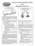
1
INSTALLATION INSTRUCTIONS
AND
OWNER'S MANUAL
CAST IRON
UNVENTED
ROOM HEATER
MODELS
VFCM-25-3
VFCR-25-3
VFCT-25-3
Thisappliancemaybeinstalledinanaftermarket,
permanently located, manufactured (mobile)
home, where not prohibited by local codes.
This appliance is only for use with the type of
gas indicated on the rating plate. This appliance
is not convertible for use with other gases.
WARNING: If the information in these instructions are not followed exactly, a fire or explosion
may result causing property damage, personal
injury or loss of life.
— Do not store or use gasoline or other flammable vapors and liquids in the vicinity of this or
any other appliance.
— WHAT TO DO IF YOU SMELL GAS
• Do not try to light any appliance.
• Do not touch any electrical switch; do not
use any phone in your building.
• Immediately call your gas supplier from a
neighbor’s phone. Follow the gas supplier’s instructions.
• If you cannot reach your gas supplier, call
the fire department.
— Installation and service must be performed by
a qualified installer, service agency or the gas
supplier.
16937-4-0806
EFFECTIVE DATE
AUGUST 2006
Installer: Leave this manual with the appliance.
Consumer: Retain this manual for future reference.
This is an unvented gas-fired heater. It uses air
(oxygen) from the room in which it is installed.
Provisions for adequate combustion and ventilation
air must be provided. Refer to page 6.
WARNING: If not installed, operated and maintained in accordance with the manufacturer's
instructions, this product could expose you to
substances in fuel or from fuel combustion which
can cause death or serious illness.
WATER VAPOR: A BY-PRODUCT OF
UNVENTED ROOM HEATERS
Water vapor is a by-product of gas combustion. An
unvented room heater produces approximately one
(1) ounce (30ml) of water for every 1,000 BTU's
(.3KW's) of gas input per hour. Refer to page 6.
Page 1
TABLE OF CONTENTS
SECTION
PAGE
Important Safety Information ....................................................................................................................................................... 3
Safety Information for Users of LP Gas ....................................................................................................................................... 4
Introduction................................................................................................................................................................................... 5
Specifications ................................................................................................................................................................................ 5
Water Vapor: A By-Product of Unvented Room Heaters ............................................................................................................. 6
Provisions for Adequate Combustion and Ventilation Air ............................................................................................................ 6
Gas Supply .................................................................................................................................................................................... 7
Clearances .................................................................................................................................................................................... 8
Assembly of Cast Iron (Outer Casing) Stove Casting .............................................................................................................. 8-9
Log Placement ........................................................................................................................................................................... 10
Placement of Glowing Embers ................................................................................................................................................... 10
Important Guidelines .................................................................................................................................................................. 11
VFCR-25, VFCT-25 Photos........................................................................................................................................................ 12
Operation Instructions/Flame Appearance ................................................................................................................................. 13
VFCM-25 Lighting Instructions ................................................................................................................................................ 14
VFCR-25 Lighting Instructions ................................................................................................................................................. 15
VFCT-25 Lighting Instructions ................................................................................................................................................. 16
Pilot Flame Characteristics .................................................................................................................................................... 17-18
Wiring ........................................................................................................................................................................................ 18
Millivolt Operating Instructions ................................................................................................................................................. 19
Operating Guidelines .................................................................................................................................................................. 20
Maintenance ................................................................................................................................................................................ 20
Troubleshooting ........................................................................................................................................................................ 21
Parts List ..................................................................................................................................................................................... 22
Parts View .................................................................................................................................................................................. 23
How to Order Repair Parts ......................................................................................................................................................... 23
Service Notes .............................................................................................................................................................................. 24
Page 2
16937-4-0806
IMPORTANT SAFETY INFORMATION
THIS IS A HEATING APPLIANCE
DO NOT OPERATE THIS APPLIANCE WITHOUT FRONT PANEL INSTALLED.
• An unvented room heater having an input rating of more than
6,000 Btu per hour shall not be installed in a bathroom.
• An unvented room heater having an input rating of more than
10,000 Btu per hour shall not be installed in a bedroom or
bathroom.
• Due to high temperatures, the appliance should be located
out of traffic and away from furniture and draperies.
• Children and adults should be alerted to the hazard of high
surface temperature and should stay away to avoid burns or
clothing ignition.
• DO NOT use this room heater if any part has been under water.
Immediately call a qualified service technician to inspect the
room heater and to replace any part of the control system and
any gas control which has been under water.
• Due to high surface temperatures, keep children, clothing and
furniture away.
• Under no circumstances should any solid fuels (wood, coal,
paper or cardboard etc.) be used in this appliance.
• The flow of combustion and ventilation air must not be obstructed
in any way.
• Young children should be carefully supervised when they
are in the same room with the appliance.
• Keep appliance area clear and free from combustible materials,
gasoline and other flammable vapors and liquids.
• Do not place clothing or other flammable material on or near
the appliance.
• WARNING: Do not use a blower insert, heat exchanger insert
or other accessory not approved for use with this heater.
• WARNING: This appliance is equipped for (natural gas or
propane) gas. Field conversion is not permitted.
• Keep burner and control compartment clean.
• Installation and repair should be done by a QUALIFIED
SERVICE PERSON. The appliance should be inspected
before use and at least annually by a professional service
person. More frequent cleaning may be required due to
excessive lint from carpeting, bedding materials, etc. It is
imperative that control compartments, burners and circulating
air passageways of the appliance be kept clean.
• DO make a periodic visual check of pilot and burners. Clean
and replace damaged parts.
WARNING
When used without adequate combustion and ventilation air,
heater may give off CARBON MONOXIDE, an odorless,
poisonous gas.
Do not install heater until all necessary provisions are
made for combustion and ventilation air. Consult the written instructions provided with the heater for information
concerning combustion and ventilation air. In the absence
of instructions, refer to the National Fuel Gas Code, ANSI
Z223.1, Section 5.3 or applicable local codes.
This heater is equipped with a PILOT LIGHT SAFETY SYSTEM designed to turn off the heater if not enough fresh air is
available.
DO NOT TAMPER WITH PILOT LIGHT SAFETY
SYSTEM!
If heater shuts off, do not relight until you provide fresh air.
If heater keeps shutting off, have it serviced. Keep burner and
control compartment clean.
16937-4-0806
CARBON MONOXIDE POISONING MAY LEAD TO
DEATH.
Early signs of carbon monoxide poisoning resemble the flu,
with headache, dizziness and/or nausea. If you have these
signs, heater may not be working properly. Get fresh air at
once! Have heater serviced.
Some people — pregnant women, persons with heart or lung
disease, anemia, those under the influence of alcohol, those at
high altitudes — are more affected by carbon monoxide than
others.
The pilot light safety system senses the depletion of oxygen
at its location. If this heater is installed in a structure having a
high vertical dimension, the possibility exists that the oxygen
supply at the higher levels will be less than that at the heater. In
this type of application, a fan to circulate the structure air will
minimize this effect. The use of this fan will also improve the
comfort level in the structure. When a fan is used to circulate
air, it should be located so that the air flow is not directed at
the burner.
Page 3
SAFETY INFORMATION FOR USERS OF LP-GAS
Propane (LP-Gas) is a flammable gas which can cause fires and
explosions. In its natural state, propane is odorless and colorless.
You may not know all the following safety precautions which
can protect both you and your family from an accident. Read
them carefully now, then review them point by point with the
members of your household. Someday when there may not be
a minute to lose, everyone's safety will depend on knowing
exactly what to do. If, after reading the following information,
you feel you still need more information, please contact your
gas supplier.
LP-GAS WARNING ODOR
If a gas leak happens, you should be able to smell the gas because of the odorant put in the LP-Gas.
That's your signal to go into immediate action!
Do not operate electric switches, light matches, use your
• Use your neighbor's phone and call a trained LP-Gas service
phone. Do not do anything that could ignite the gas.
person and the fire department. Even though you may not
Get everyone out of the building, vehicle, trailer, or area.
continue to smell gas, do not turn on the gas again. Do not
Do that IMMEDIATELY.
re-enter the building, vehicle, trailer, or area.
Close all gas tank or cylinder supply valves.
• Finally, let the service man and firefighters check for escaped
LP-Gas is heavier than air and may settle in low areas such
gas. Have them air out the area before you return. Properly
as basements. When you have reason to suspect a gas leak,
trained LP-Gas service people should repair the leak, then
keep out of basements and other low areas. Stay out until
check and relight the gas appliance for you.
firefighters declare them to be safe.
•
•
•
•
NO ODOR DETECTED - ODOR FADE
Some people cannot smell well. Some people cannot smell the
odor of the chemical put into the gas. You must find out if you
can smell the odorant in propane. Smoking can decrease your
ability to smell. Being around an odor for a time can affect your
sensitivity or ability to detect that odor. Sometimes other odors
in the area mask the gas odor. People may not smell the gas odor
or their minds are on something else. Thinking about smelling
a gas odor can make it easier to smell.
The odorant in LP-gas is colorless, and it can fade under some
circumstances. For example, if there is an underground leak, the
movement of the gas through soil can filter the odorant. Odorants
in LP-Gas also are subject to oxidation. This fading can occur if
there is rust inside the storage tank or in iron gas pipes.
The odorant in escaped gas can adsorb or absorb onto or into
walls, masonry and other materials and fabrics in a room. That
will take some of the odorant out of the gas, reducing its odor
intensity.
LP-Gas may stratify in a closed area, and the odor intensity
could vary at different levels. Since it is heavier than air, there
may be more odor at lower levels. Always be sensitive to the
slightest gas odor. If you detect any odor, treat it as a serious
leak. Immediately go into action as instructed earlier.
SOME POINTS TO REMEMBER
•
Learn to recognize the odor of LP-gas. Your local LP-Gas
Dealer can give you a "Scratch and Sniff" pamphlet. Use it
to find out what the propane odor smells like. If you suspect
that your LP-Gas has a weak or abnormal odor, call your
LP-Gas Dealer.
•
If you are not qualified, do not light pilot lights, perform
service, or make adjustments to appliances on the LP-Gas
system. If you are qualified, consciously think about the
odor of LP-Gas prior to and while lighting pilot lights or
performing service or making adjustments.
•
Sometimes a basement or a closed-up house has a musty
smell that can cover up the LP-Gas odor. Do not try to light
pilot lights, perform service, or make adjustments in an area
where the conditions are such that you may not detect the
odor if there has been a leak of LP-Gas.
•
Odor fade, due to oxidation by rust or adsorption on walls
of new cylinders and tanks, is possible. Therefore, people
should be particularly alert and careful when new tanks or
cylinders are placed in service. Odor fade can occur in new
tanks, or reinstalled old tanks, if they are filled and allowed
Page 4
to set too long before refilling. Cylinders and tanks which
have been out of service for a time may develop internal rust
which will cause odor fade. If such conditions are suspected
to exist, a periodic sniff test of the gas is advisable. If you
have any question about the gas odor, call your LP-gas dealer.
A periodic sniff test of the LP-gas is a good safety measure
under any condition.
•
If, at any time, you do not smell the LP-Gas odorant and you
think you should, assume you have a leak. Then take the same
immediate action recommended above for the occasion when
you do detect the odorized LP-Gas.
•
If you experience a complete "gas out," (the container is under no vapor pressure), turn the tank valve off immediately.
If the container valve is left on, the container may draw in
some air through openings such as pilot light orifices. If this
occurs, some new internal rusting could occur. If the valve is
left open, then treat the container as a new tank. Always be
sure your container is under vapor pressure by turning it off
at the container before it goes completely empty or having
it refilled before it is completely empty.
16937-4-0806
INTRODUCTION
Instructions to Installer
1. Installer must leave instruction manual with owner after
installation.
2. Installer must have owner fill out and mail warranty card
supplied with unvented room heater.
3. Installer should show owner how to start and operate unvented
room heater.
Always consult your local Building Department regarding
regulations, codes or ordinances which apply to the installation
of an unvented room heater.
This appliance may be installed in an aftermarket* permanently
located, manufactured (mobile) home, where not prohibited by
state or local codes.
*Aftermarket: Completion of sale, not for purpose of resale, from
the manufacturer.
This appliance is only for use with the type of gas indicated on
the rating plate.
WARNING: ANY CHANGE TO THIS HEATER OR ITS
CONTROLS CAN BE DANGEROUS.
Any safety screen or guard removed for servicing an appliance
must be replaced prior to operating the heater.
General Information
This unvented heater is design certified in accordance with
American National Standards Institute Z21.11.2 by the Canadian
Standards Association as an Unvented Room Heater and should
be installed according to these instructions.
Attention: During initial use of ceramic log you will detect an
odor as the ceramic log is cured. Also, during the curing process
the ceramic log will burn with a yellow flame.
Any alteration of the original design, installed other than as
shown in these instructions or use with a type of gas not shown
on the rating plate is the responsibility of the person and company
making the change.
Important
All correspondence should refer to complete Model Number,
Serial Number and type of gas.
BRUCE SPECIAL COPY
Notice: During initial firing of this unit, its paint will bake out,
and smoke will occur. To prevent triggering of smoke alarms,
ventilate the room in which the unit is installed.
Qualified Installing Agency
Installation and replacement of gas piping, gas utilization
equipment or accessories and repair and servicing of equipment
shall be performed only by a qualified agency. The term "qualified
agency" means any individual, firm, corporation or company
which either in person or through a representative is engaged in
and is responsible for (a) the installation or replacement of gas
piping or (b) the connection, installation, repair or servicing of
equipment, who is experienced in such work, familiar with all
precautions required and has complied with all the requirements
of the authority having jurisdiction.
State of Massachusetts: The installation must be made by a
licensed plumber or gas fitter in the Commonwealth of Massachusetts.
Sellers of unvented propane or natural gas-fired supplemental
room heaters shall provide to each purchaser a copy of 527
CMR 30 upon sale of the unit.
The installation must conform with local codes or, in the absence
of local codes, with the National Fuel Gas Code, ANSI Z223.1/
NFPA 54.*
*Available from the American National Standards Institute, Inc., 11 West 42nd
St., New York, N.Y. 10036.
High Altitudes
For altitudes/elevations above 2,000 feet (610m), ratings should be
reduced at the rate of 4 percent for each 1,000 feet (305m) above
sea level. Contact the manufacturer or your gas company before
changing spud/orifice size.
Well Head Gas Installations
Some natural gas utilities use "well head" gas. This may affect the
Btu output of the unit. Contact the gas company for the heating
value. Contact the manufacturer or your gas company before
changing spud/orifice size.
WARNING: Failure to keep the primary air opening(s) of the
burner(s) clean may result in sooting and property damage.
SPECIFICATIONS
Model
VFCR-25
VFCM-25
Input BTU/HR (KW/H)
Max. (LP/NAT)
25,000 ( 7.3)
25,000 (7.3)
Medium
——
20,000 (5.9)
Min. (LP/NAT)
17,500 (5.1)
15,000 (4.4)
Height
26 3/4" (679mm)
26 3/4" (679mm)
Width
26 1/4" (666mm)
26 1/4" (666mm)
Depth
17 1/8" (434mm)
17 1/8" (434mm)
Gas Inlet
3/8" (9.5mm)
3/8" (9.5mm)
Stove Casting (Requires VFCR-25, VFCT-25, VFCM-25
VFCI-FB
Vent-Free Cast Iron Stove Painted Black
Accessories for VFCR-25 Only
TMV
Wall Thermostat, Millivolt -Reed Switch
FRBC
Battery Operated Remote Control
FRBTC
Battery Operated Remote Control with Thermostat
FREC
Electric Remote Control
FWS-1
Wall Switch
16937-4-0806
VFCT-25
25,000 ( 7.3)
——
17,500 (5.1)
26 3/4" (679mm)
26 1/4" (666mm)
17 1/8" (434mm)
3/8" (9.5mm)
Page 5
WATER VAPOR: A BY-PRODUCT OF UNVENTED ROOM HEATERS
Water vapor is a by-product of gas combustion. An unvented room
heater produces approximately one (1) ounce (30ml) of water for
every 1,000 BTU's (.3KW's) of gas input per hour.
Unvented room heaters must be used as supplemental heat (a
room) rather than a primary heat source (an entire house). In most
supplemental heat applications, the water vapor does not create a
problem. In most applications, the water vapor enhances the low
humidity atmosphere experienced during cold weather.
The following steps will help insure that water vapor does not
become a problem.
1. Be sure the heater is sized properly for the application, including
ample combustion air and circulation air.
2. If high humidity is experienced, a dehumidifier may be used
to help lower the water vapor content of the air.
3. Do not use an unvented room heater as the primary heat source
(an entire house).
PROVISIONS FOR ADEQUATE COMBUSTION & VENTILATION AIR
This heater shall not be installed in a confined space or unusually
tight construction unless provisions are provided for adequate
combustion and ventilation air.
The National Fuel Gas Code, ANSI Z223.1 defines a confined
space as a space whose volume is less than 50 cubic feet per
1,000 Btu per hour (4.8m3 per kw) of the aggregate input rating
of all appliances installed in that space and an unconfined space
as a space whose volume is not less than 50 cubic feet per 1,000
Btu per hour (4.8m3 per kw) of the aggregate input rating of all
appliances installed in that space. Rooms communicating directly
with the space in which the appliances are installed, through
openings not furnished with doors, are considered a part of the
unconfined space.
The following example is for determining the volume of a typical
area in which the VFCM-25 may be located and for determining
if this area fits the definition of an unconfined space.
The maximum input of the VFCM-25 is 25,000 Btu per hour.
Based on the 50 cubic feet per 1,000 Btu per hour formula, the
minimum area that is an unconfined space for installation of the
VFCM-25 is 1,250 cubic feet, 50 cubic feet x 25 = 1,250 cubic feet.
To determine the cubic feet of the area in which the VFCM-25 is
to be installed, measure the length, width and height of the area.
Example: The area measures 16 feet in length, 10 feet in width
and 8 feet in height, the area is 1,280 cubic feet. The VFCM-25
can be installed in this unconfined space with no requirement to
provide additional combustion and ventilation air.
Page 6
Warning: If the area in which the heater may be operated is smaller
than that defined as an unconfined space or if the building is of
unusually tight construction, provide adequate combustion and
ventilation air by one of the methods described in the National Fuel
Gas Code, ANSI Z223.1, Section 5.3 or applicable local codes.
Unusually Tight Construction
The air that leaks around doors and windows may provide enough
fresh air for combustion and ventilation. However, in buildings
of unusually tight construction, you must provide additional
fresh air.
Unusually tight construction is defined as construction
where:
a. Walls and ceilings exposed to the outside atmosphere have
a continuous water vapor retarder with a rating of one perm
or less with openings gasketed or sealed, and
b. Weatherstripping has been added on openable windows
and doors, and
c. Caulking or sealants are applied to areas such as joints
around window and door frames, between sole plates and
floors, between wall-ceiling joints, between wall panels,
at penetrations for plumbing, electrical, and gas lines, and
at other openings.
If the heater is installed in a building of unusually tight construction,
adequate air for combustion, ventilation and dilution of flue gases
shall be provided in accordance with ANSI Z223.1/NFPA54.
16937-4-0806
GAS SUPPLY
Check all local codes for requirements, especially for the size and type
of gas supply line required.
Note: Never use plastic pipe. Check to confirm whether your local codes
allow copper tubing or galvanized.
Note: Since some municipalities have additional local codes, it is always
best to consult your local authority and installation code.
Recommended Gas Pipe Diameter
Pipe Length
(Feet)
0-10
10-40
40-100
100-150
Schedule 40 Pipe
Inside Diameter
Nat.
L.P.
1/2"
3/8"
12.7mm 9.5mm
1/2"
1/2"
12.7mm 12.7mm
1/2"
1/2"
12.7mm 12.7mm
3/4"
1/2"
19mm
12.7mm
Tubing, Type L
Outside Diameter
Nat.
L.P.
1/2"
3/8"
12.7mm 9.5mm
5/8"
1/2"
15.9mm 12.7mm
3/4"
1/2"
19mm
12.7mm
7/8"
3/4"
22.2mm 19mm
Figure 1
Installing a New Main Gas Cock
Each appliance should have its own manual gas cock.
A manual main gas cock should be located in the vicinity of
the unit. Where none exists, or where its size or location is not
adequate, contact your local authorized installer for installation
or relocation.
Compounds used on threaded joints of gas piping shall be resistant
to the action of liquefied petroleum gases. The gas lines must be
checked for leaks by the installer. This should be done with a soap
solution watching for bubbles on all exposed connections, and if
unexposed, a pressure test should be made.
Never use an exposed flame to check for leaks. Appliance must be
disconnected from piping at inlet of control valve and pipe capped
or plugged for pressure test. Never pressure test with appliance
connected; control valve will sustain damage!
A gas valve and ground joint union should be installed in the gas
line upstream of the gas control to aid in servicing. It is required
16937-4-0806
BRUCE SPECIAL COPY
by the National Fuel Gas Code that a drip line be installed near
the gas inlet. This should consist of a vertical length of pipe tee
connected into the gas line that is capped on the bottom in which
condensation and foreign particles may collect.
Method of Installing a Tee Fitting Sediment Trap
The use of the following gas connectors is recommended:
— ANS Z21.24 Appliance Connectors of Corrugated Metal Tubing
and Fittings
— ANS Z21.45 Assembled Flexible Appliance Connectors of Other
Than All-Metal Construction
The above connectors may be used if acceptable by the authority
having jurisdiction. The state of Massachusetts requires that a flexible
appliance connector cannot exceed three feet in length.
Pressure Testing of the Gas Supply System
1. To check the inlet pressure to the gas valve, a 1/8" (3mm) N.P.T.
plugged tapping, accessible for test gauge connection, must be
placed immediately upstream of the gas supply connection to
the appliance.
2. The appliance and its appliance main gas valve must be
disconnected from the gas supply piping system during any
pressure testing of that system at test pressures in excess of 1/2
psig (3.5 kPa).
3. The appliance must be isolated from the gas supply piping system
by closing its equipment shutoff valve during any pressure testing
of the gas supply piping system at test pressures equal to or less
than 1/2 psig (3.5 kPa).
Attention! If one of the above procedures results in pressures in
excess of 1/2 psig (14" w.c.) (3.5 kPa) on the appliance gas valve,
it will result in a hazardous condition.
Checking Manifold Pressure
VFCR-25 Natural gas will have a manifold pressure of approximately
3.5" w.c. (.871kPa) for maximum input or 1.7" w.c. (.423kPa)
for minimum input at the pressure regulator outlet with the inlet
pressure to the pressure regulator from a minimum of 4.5" w.c.
(1.120kPa) for the purpose of input adjustment to a maximum of
10.5" w.c. (2.614kPa). VFCM-25 and VFCT-25 Natural gas will
have a manifold pressure of approximately 6.0" w.c. (1.49kPa) at
the pressure regulator outlet with the inlet pressure to the pressure
regulator from a minimum of 7.0" w.c. (1.74kPa) for the purpose of
input adjustment to a maximum of 10.5" w.c. (2.615kPa). VFCR-25
Propane gas will have a manifold pressure approximately 10.0"w.c.
(2.49kPa) for maximum input or 6.3"w.c. (1.568kPa) for minimum
input at the pressure regulator outlet with the inlet pressure to the
pressure regulator from a minimum of 11.0"w.c. (2.739kPa) for the
purpose of input adjustment to a maximum of 13.0"w.c. (3.237kPa).
VFCM-25 and VFCT-25 Propane gas will have a manifold pressure
approximately 10.0"w.c. (2.49kPa) at the pressure regulator outlet
with the inlet pressure to the pressure regulator from a minimum
of 11.0"w.c. (2.739kPa) for the purpose of input adjustment to a
maximum of 13.0"w.c. (3.237kPa).
NOTE: The gas control is equipped with a captured screw type
pressure test point, therefore it is not necessary to provide a 1/8"
test point up stream of the control.
A test gauge connection is located downstream of the gas appliance
pressure regulator for measuring gas pressure. The connection is a
1/8 inch 3mm) N.P.T. plugged tapping.
Page 7
CLEARANCES
When facing the front of the appliance the following minimum
clearances to combustible construction must be maintained.
Top of appliance (ceiling)
36 inches
Rear Wall
3 inches
Side Wall
6 inches
Heater Corners (45° angle) to Wall
4 inches
Floor
0 inches
Figure 2
Provide adequate clearances around air openings.
Adequate accessibility clearances for purposes of servicing and
proper operation must be provided.
Installation on Rugs and Vinyl
If this appliance is installed directly on carpeting, vinyl or other
combustible material, other than wood flooring, the appliance shall
be installed on a metal or wood panel extending the full width and
depth of the appliance.
Figure 3
Figure 4
Assembly of Cast Iron (Outer Casing) Stove Casting
Appliance Hardware Package Parts List
Part
Description
Part
Number
Quantity
Supplied
1/4-20 x 3/8" Phillips Head Bolt
R-3646
8
1/4" 9/32 Washer
R-1150
8
10 - 24 Nut
R-1118
2
Attention: Included in the hardware package are (8) 1/4" inside
diameter washers. A 1/4" washer may be used with a 1/4-20 x 3/8"
bolt when assembling the stove casting parts. If a bolt hole is not
tapped deep enough for a tight fit between stove casting parts, the
1/4" washer can be used as a shim to provide a tight fit.
The 1/4" washers are not required for assembly of the stove casting
if all the bolt holes are tapped to a proper depth.
Page 8
1. Remove casting from shipping carton. Place casting on nonabrasive surface.
2. Remove burner assembly, logs, hardware and sheet metal
parts from shipping carton.
3. Attach rear cover to casting sides with 1/4 - 20 x 3/8" bolts
(2 per side) as shown in Figure 5.
4. Attach casing bottom to casting sides with 1/4 - 20 x 3/8"
bolts (2 per side).
5. Align and place (2) clearance holes on front legs of burner
assembly over (2) rear weld studs in casing bottom.
6. For VFCR-25 only, attach green wire to the TH terminal on
gas valve. Attach black wire to the TH/TP terminal on gas
valve from wiring harness on valve cover plate.
7. Attach three (3) knob extensions onto gas valve as shown in
Figure 6.
8. Align and attach (2) clearance holes on MV switch bracket as
shown in Figure 6 onto (2) front weld studs in casing bottom
with (2) 10-24 nuts.
9. Attach casting front onto casting sides as shown in Figure
7.
16937-4-0806
FLANGE TOWARDS BACK
REAR COVER
RIGHT SIDE
LEFT SIDE
DETAIL VIEW
CASING BOTTOM
(4) LEVELING BOLTS
Figure 5
Figure 6
16937-4-0806
Figure 7
Page 9
LOG PLACEMENT
Every burner is shipped with a protective cover. This cover must
be removed before log placement.
The positioning of the logs is critical to the safe and clean operation
of this heater. Sooting and other problems may result if the logs
are not properly and firmly positioned in the appliance.
During initial operation of the new heater, burning logs will
give off a paper burning smell and orange flames will be
present. Simply open the windows for a few hours to vent the
odor.
PROPER INSTALLATION SEQUENCE:
1. Install the rear log behind the pilot assembly directly on the
pins on each side of the rear log shield.
2. Install the front log in front of the grate. The log is located into
a notch area in the front grate area.
Refer to Figure 8 for the following warning.
Warning: Failure to position the parts in accordance with this
diagram or failure to use only parts specifically approved with
this appliance may result in property damage or personal
injury.
Figure 8
PLACEMENT OF GLOWING EMBERS (rock wool)
Provided with the log set is a small bag of glowing embers (rock
wool) to be placed between logs on the flat metal surface of the
burner.
Placement of the glowing embers (rock wool) is very individual
and light coverage of the areas indicated will provide your best
effects. We recommend separation of the rock wool by hand and
make your coverage as light and fluffy as possible.
Place just enough rock wool on the burner to obtain the glow and
a gold, yellow flame.
Page 10
Do not place rock wool over large ports in rear portion of
burner.
Rock wool should not be placed in the area of the pilot assembly.
Replacement of loose material (glowing embers) must be
purchased from Empire Comfort Systems, Inc. Application of
excess loose material (glowing embers) may adversely affect
performance of the heater. WARNING: All previously applied
loose material must be removed prior to reapplication.
Refer to Parts List, Page 22 to order loose material (rock wool).
16937-4-0806
IMPORTANT INSTALLATION GUIDELINES
Proper Log Placement
Log placement is critical to proper burner performance. Logs
must be correctly positioned onto the burner. The photos in this
manual show the proper pinned position for logs on this set.
Owners need to be shown proper log placement and instructed
not to move the logs.
Logs must fit firmly onto the burner when positioned as shown
in the photos. Misformed logs or logs with sloppy pin holes must
be replaced.
Proper Placement of Rock Wool and Decorative Lava Rock
Rock wool can be added to burners for a glowing ember effect.
It must be positioned only on the front portion of the burner. The
photos in this manual show the proper placement of rock wool.
Decorative lava rock or small wood pieces should never be placed
on the burner. These items are only for placement on the floor of
the fireplace or firebox.
Proper Primary Airflow into Burner
For proper burner operation and flame appearance, the flow of
primary air into the venturi tube, located on the rear of the burner,
must not be reduced. This flow of air is reduced if dirt, lint or other
obstructions build-up around or inside the venturi. Any obstruction
in the venturi tube area must be removed. The flow of air into the
venturi is also reduced if the gas orifice isn’t centered in the venturi
inlet and/or is not aligned with the venturi. Any misalignment of
the burner orifice may be corrected by bending the shutter cap
holding the orifice to the inlet of the venturi tube.
Ceiling Fans, Portable Fans or Logs Installed Near Cold Air
Returns
Ceiling fans or oscillating floor type fans need to be monitored
during the operation of vent-free logs. If the air blows directly
into the flame causing it to impinge on the log set, or firebox, it
should be turned off or redirected. Ceiling fans could be reversed
to possibly eliminate flame impingement, and the floor fan could
be redirected. Upon installation, be aware of any cold air returns
or vents in the proximity of the log set. Any draft created around
a vent-free log set can cause the flame to impinge on the log and
create a sooting situation.
16937-4-0806
WARNING: Do not allow fans to blow directly into the fireplace.
Avoid any drafts that alter burner flame patterns.
WARNING: Do not use a blower insert, heat exchanger insert or
other accessory not approved for use with this heater.
Candles
Avoid the use of scented or decorative candles while the log set
is in operation. Candles produce a residue in the air that creates a
soot like substance. Burning candles while the log set is operating
magnifies the problem. It should be noted that candles, in general,
produce soot. The amount of time burned and the quantity of
candles burned will determine the amount of soot produced and
deposited.
Make Owners Aware of Proper Log Set Operation
Properly installed and properly maintained log sets do not deposit
soot on the logs. If users see soot appear on a log, call for service.
Do not continue to operate the log set.
Sunken Fireplace
If installing this unit into a sunken fireplace, you must raise the floor
to insure adequate airflow and guard against sooting. Raise fireplace
floor using a non-combustible material, which is secure.
Glass Doors
Make sure that glass doors are open during all operations of the
logset. The opening of the glass door frame should be the dimension
used for the minimum front opening of the firebox.
Woodburning Fireplaces
The interior of the firebox and the chimney should be cleaned and
free of all creosote before installing a gas burning log set. Creosote
will soften when heated and can drop on the logset causing odors
and possibly sooting.
WARNING: Before installing in a solid-fuel burning fireplace,
the chimney flue and firebox must be cleaned of soot, creosote,
ashes and loose paint by a qualified chimney cleaner.
Page 11
VFCR -25, VFCT-25 PHOTOS
Page 12
16937-4-0806
OPERATION INSTRUCTIONS/FLAME APPEARANCE
Flames from the pilot (rear right back side of the pan burner) as
well as the main flame should be visually checked as the log set
is installed.
In normal operation at full rate after 10 to 15 minutes, the flame
appearance should be sets of yellow flames.
NOTE: all flames will be random by design, flame height will
go up and down.
Glowing embers (rock wool) can cover the pan burner in between
the front and middle logs, but very little is necessary to cover this
area. Excess ember material causes the yellow flame to become
orange and stringy. Apply just enough to obtain slow glow and a
gold, yellow flame.
VFCM-25
Figure 10
Avoid any drafts that alter burner flame patterns. Do not allow
fans to blow directly into fireplace. Do not place a blower inside
the burner area of the firebox. Ceiling fans may create drafts that
alter flame patterns. Sooting and improper burning will result.
During manufacturing, fabricating and shipping, various
components of this appliance are treated with certain oils, films or
bonding agents. These chemicals are not harmful, but may produce
annoying smoke and smells as they are burned off during the initial
operation of the appliance, possibly causing headaches or eye or
lung irritation. This is a normal and temporary occurrence.
The initial break-in operation should last 2-3 hours with the burner
at the highest setting. Provide maximum ventilation by opening
windows or doors to allow odors to dissipate. Any odors remaining
after this initial break-in will be slight and will disappear with
continued use.
VFCR-25
Figure 11
VFCT-25
Figure 12
16937-4-0806
Page 13
VFCM-25 LIGHTING INSTRUCTIONS
FOR YOUR SAFETY READ BEFORE LIGHTING
WARNING: If you do not follow these instructions exactly, a fire or explosion may result
causing property damage, personal injury or loss of life.
A. This appliance has a pilot which must be lighted by hand.
When lighting the pilot, follow these instructions exactly.
B. BEFORE LIGHTING smell all around the appliance area
for gas. Be sure to smell next to the floor because some gas
is heavier than air and will settle on the floor.
WHAT TO DO IF YOU SMELL GAS
• Do not try to light any appliance.
• Do not touch any electrical switch;
do not use any phone in your building.
• Immediately call your gas supplier from a neighbor's
phone. Follow the gas supplier's instructions.
• If you cannot reach your gas supplier, call the fire
department.
C. Use only your hand to push in or turn the gas control
knob. Never use tools. If the knob will not push in or
turn by hand, don't try to repair it; call a qualified service
technician. Force or attempted repair may result in a fire
or explosion.
D. Do not use this appliance if any part has been under
water. Immediately call a qualified service technician
to inspect the appliance and to replace any part of the
control system and any gas control which has been under
water.
LIGHTING INSTRUCTIONS
1. STOP! Read the safety information.
2. Make sure the manual shutoff valve is fully open.
3. This heater is equipped with an ignition device (piezo) which
automatically lights the pilot.
4. Refer to Figure 11 for the location of the piezo ignitor and
control knob. Push in gas control knob slightly and turn
control knob clockwise
to the OFF position.
NOTE: Knob cannot be turned to OFF unless knob is pushed
in slightly. Do not force.
5. Wait ten (10) minutes to clear out any gas. Then smell for
gas, including near the floor. If you smell gas STOP! Follow
the instructions under ‘What To Do If You Smell Gas”. If
you do not smell gas, go to the next step.
6. From OFF position, push in gas control knob slightly and
turn counterclockwise
to the PILOT position. Push
in and hold control knob for 5 seconds.
NOTE: If you are running the heater for the first time, it will
be necessary to press in the control knob for 30 seconds to
allow air to bleed out of the gas piping.
7. With the control knob pushed in, push and release the piezo
ignitor button to light the ODS pilot. The pilot is located on
the right rear side of the heater, behind the front log and in
front of the rear log. If piezo ignitor does not light the pilot,
refer to “Match Lighting Instructions”.
8. Hold the control knob in for an additional 10 seconds to
prevent the ODS pilot from shutting off the gas while the
thermocouple is warming up.
9. Release the control knob.
• If the knob does not pop out when released, stop
and immediately call your service technician or gas
supplier.
• If the ODS pilot will not stay lit after several tries, push
and turn the gas control knob clockwise
to
OFF and wait 15 seconds. Repeat steps 6 through 9.
10. Push in control knob and turn to desired setting (1, 2,
3). The control knob must be set at either the low or
high position, and the control knob will pop out when
positioned correctly. Do not set the control knob at a
position between pilot (1, 2, 3).
TO TURN OFF GAS TO APPLIANCE
1. Turn control knob clockwise
completely shut off the heater.
Page 14
to OFF position to
16937-4-0806
VFCR-25 LIGHTING INSTRUCTIONS
FOR YOUR SAFETY READ BEFORE LIGHTING
WARNING: If you do not follow these instructions exactly, a fire or explosion may result
causing property damage, personal injury or loss of life.
A. This appliance has a pilot which must be lighted by hand.
When lighting the pilot, follow these instructions exactly.
B. BEFORE LIGHTING smell all around the appliance area
for gas. Be sure to smell next to the floor because some gas
is heavier than air and will settle on the floor.
WHAT TO DO IF YOU SMELL GAS
• Do not try to light any appliance.
• Do not touch any electrical switch;
do not use any phone in your building.
• Immediately call your gas supplier from a neighbor's
phone. Follow the gas supplier's instructions.
• If you cannot reach your gas supplier, call the fire
department.
C. Use only your hand to push in or turn the gas control
knob. Never use tools. If the knob will not push in or
turn by hand, don't try to repair it; call a qualified service
technician. Force or attempted repair may result in a fire
or explosion.
D. Do not use this appliance if any part has been under
water. Immediately call a qualified service technician
to inspect the appliance and to replace any part of the
control system and any gas control which has been under
water.
LIGHTING INSTRUCTIONS
1. STOP! Read the safety information label.
2. Make sure the manual shutoff valve is fully open.
3. This gas log set is equipped with an ignition device (piezo)
which lights the pilot. If piezo ignitor does not light the pilot,
refer to instructions for “Match Lighting”.
4. Turn gas control knob clockwise
to the “OFF”
position, set the thermostat to the lowest setting and turn
ON/OFF switch to OFF position.
5. Wait ten (10) minutes to clear out any gas. Then smell for
gas, including near the floor. If you smell gas STOP! Follow
“B” in the safety information label. If you do not smell gas,
go to the next step.
6. From OFF position, turn the gas control knob counterclockwise
to “Pilot” position. Push in and hold control
knob for 5 seconds.
7.With the control knob pushed in, push and release the piezo
ignitor button to light the ODS pilot. The pilot is located on
the right rear side of the heater, behind the front log and in
front of the rear log. If piezo ignitor does not light the pilot,
refer to “Match Lighting Instructions”.
8. Continue pushing the control knob in for a further 60
seconds to prevent the flame detector from shutting off
the gas while the probe is warming up. Release the control
knob.
9. Turn gas control knob counterclockwise
to the
“ON” position.
10. After the pilot has been lit for one minute, the burner can
be turned on. Turn the ON/OFF switch to “ON” position
or adjust thermostat to desired setting.
11. If the gas logs will not operate, follow the instructions
“To Turn Off Gas To Appliance” and call your service
technician or gas supplier.
Wait 30 seconds before readjusting the heater when the control
knob has been turned down to a lower setting.
PIEZO
IGNITOR
HI/LO
REGULATOR
CONTROL
KNOB
TO TURN OFF GAS TO APPLIANCE
1. Turn control knob clockwise
completely shut off the heater.
16937-4-0806
to OFF position to
2. If applicable: Turn ON/OFF switch to OFF position and/or
set thermostat (if present) to lowest setting. If applicable:
Turn off all electric power to the heater.
Page 15
VFCT-25 LIGHTING INSTRUCTIONS
FOR YOUR SAFETY READ BEFORE LIGHTING
WARNING: If you do not follow these instructions exactly, a fire or explosion may result
causing property damage, personal injury or loss of life.
A. This appliance has a pilot which must be lighted by hand.
When lighting the pilot, follow these instructions exactly.
B. BEFORE LIGHTING smell all around the appliance area
for gas. Be sure to smell next to the floor because some
gas is heavier than air and will settle on the floor.
WHAT TO DO IF YOU SMELL GAS
• Do not try to light any appliance.
• Do not touch any electrical switch;
do not use any phone in your building.
• Immediately call your gas supplier from a neighbor's
phone. Follow the gas supplier's instructions.
• If you cannot reach your gas supplier, call the fire
department.
C. Use only your hand to push in or turn the gas control
knob. Never use tools. If the knob will not push in
or turn by hand, don't try to repair it; call a qualified
service technician. Force or attempted repair may result
in a fire or explosion.
D. Do not use this appliance if any part has been under
water. Immediately call a qualified service technician
to inspect the appliance and to replace any part of the
control system and any gas control which has been under
water.
LIGHTING INSTRUCTIONS
1.
2.
3.
4.
STOP! Read the safety information above.
Set thermostat (gas control knob) to lowest setting.
Turn off all electric power to the appliance (if applicable).
Push in gas control knob slightly and turn clockwise
to "OFF". Do not force.
7.
5.
6.
Wait ten (10) minutes to clear out any gas. Then smell
for gas, including near the floor. If you smell gas, STOP!
Follow "B" in the safety information above. If you don't
smell gas, go to the next step.
Find pilot - the pilot is located in front of rear log.
Turn manual gas control knob counterclockwise
to "PILOT."
8. Push in manual gas control knob all the way and hold
in. Repeatedly push the piezo ignitor button until pilot
is lit (or use a match to light pilot). Continue to hold the
control knob in for about one (1) minute after the pilot is
lit. Release knob and it will pop back up. Pilot should
remain lit. If it goes out, repeat steps 2 through 6.
• If knob does not pop up when released, stop and
immediately call your service technician or gas
supplier.
• If the pilot will not stay lit after several tries, turn
the gas control knob to "OFF" and call your service
technician or gas supplier.
9. Turn gas control knob counterclockwise
to
"HIGH".
10. Turn on all electric power to appliance (if applicable).
11. Set thermostat (gas control knob) to desired setting from
"HIGH" to "LOW".
TO TURN OFF GAS TO APPLIANCE
1.
Set thermostat (gas control knob) to lowest setting.
2.
Turn off all electric power to appliance if service is to be
performed (if applicable).
Page 16
3.
Push in gas control knob slightly and turn clockwise
to "OFF".
Do not force.
16937-4-0806
PILOT FLAME CHARACTERISTICS
Figures 13 and 16 show a correct pilot flame pattern. The correct flame
will be blue and will extend beyond the thermocouple. The flame will
surround the thermocouple just below the tip. A slight yellow flame may
occur where the pilot flame and main burner flame meet. Figures 14 and
17 show an incorrect pilot flame pattern. The incorrect pilot flame is not
touching the thermocouple. This will cause the thermocouple to cool.
When the thermocouple cools, the heater will shut down.
VFCR-25 PILOT
Figure 15
VFCM-25 AND VFCT-25 PILOT
Correct Pilot Flame Pattern
Figure 13
Correct Pilot Flame Pattern
Figure 16
Incorrect Pilot Flame Pattern
Figure 14
If pilot flame pattern is incorrect, as shown in Figure 14
• See Troubleshooting, page 19.
Cleaning and Maintenance/Pilot
Oxygen Depletion Sensor Pilot
When the pilot has a large yellow tip flame, clean the Oxygen Depletion
Sensor as follows:
1. Clean the ODS pilot by loosening nut B from the pilot tubing. When
this procedure is required, grasp nut A with an open end wrench.
2. Blow air pressure through the holes indicated by the arrows. This
will blow out foreign materials such as dust, lint and spider webs.
Tighten nut B also by grasping nut A.
16937-4-0806
Incorrect Pilot Flame Pattern
Figure 17
If pilot flame pattern is incorrect, as shown in Figure 17
• See Troubleshooting, page 19.
Page 17
PILOT FLAME CHARACTERISTICS (continued)
Cleaning and Maintenance/Pilot
Oxygen Depletion Sensor Pilot
When the pilot has a large yellow tip flame, clean the Oxygen
Depletion Sensor as follows:
1. Clean the ODS pilot by loosening nut B from the pilot tubing.
When this procedure is required, grasp nut A with an open end
wrench.
2. Blow air pressure through the holes indicated by the arrows.
This will blow out foreign materials such as dust, lint and
spider webs. Tighten nut B also by grasping nut A.
Figure 18
WIRING
Wiring Diagram for VFCR-25
Figure 19
Page 18
16937-4-0806
MILLIVOLT OPERATING INSTRUCTIONS
VFCR-25 ON/OFF/REMOTE Switch
VFCR-25 is equipped with an ON/OFF/REMOTE switch which
is located on the wiring chase. A wire harness is attached to the
ON/OFF/REMOTE switch. The brown, black and green (wires)
female push-ons attach to the ON/OFF/REMOTE switch. At the
opposite end of the wire harness, the black and green (wires) female
push-ons attach to the gas valve. An additional brown wire and
the black/red wire, which are stripped and bare, will attach to the
750 millivolt wall thermostat accessory, or, to one of the other
accessories that can be purchased for use with your log set.
Operation of ON/OFF/REMOTE Switch with no Accessories
To ignite main burner, turn the control knob on the gas valve
from the PILOT position to the ON position. Turn the ON/OFF/
REMOTE switch from the OFF position to the ON position. The
additional brown wire and black/red wire, which are stripped and
bare are not used.
Operation of ON/OFF/REMOTE Switch with Accessories
750 Millivolt Wall Thermostat
Connect the brown and black/red, stripped and bare, wires on the
ON/OFF/REMOTE switch wire harness to the wall thermostat. Turn
the ON/OFF/REMOTE switch on the valve cover to the REMOTE
position. Set the wall thermostat to the desired temperature.
It is important to use wire of a gauge proper for the length of the
wire:
RECOMMENDED WIRE GAUGES
Maximum
Length
1' to 10'
10' to 25'
25' to 35'
Wire
Gauge
18
16
14
750 Millivolt System
When you ignite the pilot, the thermocouple produces millivolts
(electrical current) which energizes the magnet in the gas valve.
After 30 seconds to 1 minute time period you can release the gas
control knob and the pilot will stay ON. Allow your pilot flame to
operate an additional one (1) to two (2) minutes before you turn the
gas control knob from the PILOT position to the ON position. This
time period allows the millivolts (electrical current) to build-up to
a sufficient level allowing the gas control to operate properly.
Wall Switch, FWS-1
Connect the brown and black/red, stripped and bare, wires on
the ON/OFF/REMOTE switch wire harness to the wall switch.
Turn the ON/OFF/REMOTE switch on the valve cover to the
REMOTE position. Pivot the rocker switch on the FWS-1 to the
ON position.
ON/OFF/REMOTE switch wire harness to the remote receiver
that is a component in the FRBC-1 and FRBTC-1. Turn the
ON/OFF/REMOTE switch on the valve cover to the REMOTE
position. Follow instructions in the FRBC-1 and FRBTC-1 to
complete installation.
Note: If batteries fail in FRBC-1 or FRBTC-1, and immediate
heat is desired, turn the ON/OFF/REMOTE switch on valve cover
from the REMOTE position to the ON position.
Wiring of ON/OFF/REMOTE Switch with 750 Millivolt Wall
Thermostat Accessory and Another Accessory
Connect the brown and black/red, stripped and bare, wires on the
ON/OFF/REMOTE switch wire harness to the 750 millivolt wall
thermostat AND to the remote receiver that is a component in the
FRBC-1 OR to the FWS-1, wall switch.
1. Connect (1) wire from the 750 millivolt wall thermostat and
(1) wire from appropriate accessory to the BROWN, stripped
and bare wire from the ON/OFF/REMOTE wire harness.
2. Connect (1) wire from the 750 millivolt wall thermostat and (1)
wire from appropriate accessory to the BLACK/RED, stripped
and bare wire from the ON/OFF/REMOTE wire harness.
Note: When the appliance is in the MANUAL mode and the
batteries fail in the FRBC-1 and immediate heat is desired,
turn the ON/OFF/REMOTE switch on valve cover from the
REMOTE position to the ON position.
Manual Operation
1. Turn ON/OFF/REMOTE switch on valve cover to REMOTE
position.
2. Turn wall thermostat OFF.
3. Turn accessory, FRBC-1 or FWS-1, ON. Appliance is now in
the manual mode. You must turn the appliance ON or OFF with
appropriate accessory.
Wall Thermostat Operation
1. Turn the ON/OFF/REMOTE switch on valve cover to REMOTE
position.
2. Turn accessory, FRBC-1 or FWS-1, OFF.
3. Turn wall thermostat ON and set appropriate temperature. Wall
thermostat will cycle the appliance ON and OFF.
Installation of Remote Receiver
1. The remote receiver can not be placed behind the gas valve
and burner assembly.
2. When facing the appliance, the remote receiver must be placed
to the left of the gas valve and burner assembly.
Refer to remote control installation and operating instructions for
more details on remote control.
Battery Operated Remote Control, FRBC-1 and FRBTC-1
Connect the brown and black/red, stripped and bare, wires on the
16937-4-0806
Page 19
OPERATING GUIDELINES
Before operating this heater, please review the safety warnings pages at
the beginning of this manual and those precautions and warnings listed
below.
1. Know what type of ignition system this model has (standing pilot)
and follow the applicable SAFETY and LIGHTING instructions.
2. Check to ensure there are no gas leaks. If you are unsure, turn gas
off to the heater and call a service person or your gas utility.
CAUTION: Clothing or other flammable material should not be placed
on or near the appliance.
WARNING: Children and adults should be alerted to the hazard of high
surface temperature and should stay away to avoid burns or clothing
ignition. Young children should be carefully supervised when they
are in the same room as the appliance.
3. Tampering is DANGEROUS and voids all warranties. Any component
that is found to be faulty, must be replaced with an approved
component.
Initial Lighting (Figure 20)
Upon completing the gas line or turning the gas valve "ON" after it has
been in the "OFF" position, a small amount of air will be in the lines.
When first lighting the appliance, it will take a few minutes for the lines to
purge themselves of this air. Once the purging is complete, the appliance
will light and operate satisfactorily.
Subsequent lightings of the appliance will not require such purging if the
gas valve is not turned to "OFF."
Standing Pilot Operation
1. Follow the SAFETY and LIGHTING INSTRUCTIONS for standing
pilot controls found in this manual and on labels found attached to
the appliance.
CAUTION: During the initial purging and subsequent lightings, never
allow the gas valve control knob to remain depressed in the "pilot" position
without pushing the piezo ignitor button at least once every second.
flame on or off with the appliance ON/OFF rocker switch, wall switch,
remote control kits or 750 millivolt wall thermostat.
NOTE: The VFCR-25 gas control valve allows you to increase or decrease
the height of the main burner flame. The control valve has a pressure
regulator with a knob as shown in Figure 20. Rotate the knob clockwise
to "HI" to increase the flame height and counterclockwise to "LO" to
decrease the flame height.
3. When the heating season is over, turn the on/off switch to "OFF" and
the control valve to "OFF". The system, including the pilot light, will
be shut down.
PIEZO
IGNITOR
HI/LO
REGULATOR
CONTROL
KNOB
Figure 20
Maximum and Minimum Input
The gas valve on the appliance allows the input to adjust between a
maximum input of 25,000 Btuh for Natural gas and Propane gas to a
minimum input of 17,500 Btuh for VFCR-25 and VFCT-25 and 15,000 Btuh
for VFCM-25. The maximum input provides the greatest amount of yellow
flame and ember glow on the log set. The minimum input substantially
decreases the yellow flame and ember glow on the log set.
2. During the heating season, leave the control valve knob in the "ON"
position. This will allow the pilot flame to remain lit. Turn the burner
MAINTENANCE
Warning: Turn off heater and let cool before cleaning.
After use, cleaning of the main burner may be required for the proper
flame. The main burner may be cleaned by applying air pressure to the
ports on the main burner.
Cleaning the Log Set and Firebox
During the annual inspection and maintenance appointment, the service
person should clean dust, lint, and any light accumulation from the logs
and the firebox area. An extra-soft brush should be used on the logs as
they are extremely fragile; a vacuum cleaner may be used on the firebox.
If at any time the logs cannot be removed or installed without forcing,
the cause must be found. The logs must never be forced.
CAUTION: The logs are durable when handled and installed properly.
However, they are delicate and may be damaged easily if not handled
with care. Handling damage to the logs is not covered by warranty.
DO NOT HANDLE LOGS WHILE THEYARE HOT. ALLOW PLENTY
OF TIME FOR THE APPLIANCE TO COOL COM-PLETELY BEFORE
HANDLING.
Page 20
Maintenance & Service Instructions
IMPORTANT: Turn off gas before servicing appliance. It is recommended
that a competent service technician perform these check-ups at the
beginning of each heating season.
• Clean Burner and Control Compartment
Keep the control compartment, logs, and burner areas surrounding the
logs clean by vacuuming or brushing at least twice a year.
Cleaning Procedure
1. Turn off pilot light at gas valve.
2. Remove front.
3. Vacuum burner compartment especially around orifice/primary air
openings.
4. Replace front.
5. Ignite pilot. (See Lighting/Operating Section of Manual)
6. Operate the main burner.
Verify proper operation after servicing.
16937-4-0806
TROUBLESHOOTING
SYMPTOMS - POSSIBLE CAUSES AND CORRECTIONS
IMPORTANT: Operating heater where impurities in air exist may create odors. Cleaning supplies, paint, paint remover, cigarette smoke, cements and
glues, new carpet or textiles, etc., create fumes. These fumes may mix with combustion air and create odors.
1. When ignitor button is pressed, there is no spark at ODS/pilot.
a. Ignitor electrode positioned wrong - Replace ignitor.
b. Ignitor electrode broken - Replace ignitor.
c. Ignitor electrode not connected to ignitor cable - Reconnect ignitor
cable.
d. Ignitor cable pinched or wet - Free ignitor cable if pinched by
any metal or tubing. Keep ignitor cable dry.
e. Broken ignitor cable - Replace ignitor cable.
f. Bad piezo ignitor - Replace piezo ignitor.
2. When ignitor button is pressed, there is spark at ODS/pilot, but no
ignition.
a. Gas supply turned off or manual shutoff valve closed - Turn on
gas supply or open manual shutoff valve.
b. Control knob not in PILOT position - Turn gas control knob to
PILOT position.
c. Control knob not pressed in while in PILOT position - Press in
control knob while in PILOT position.
d. Air in gas lines when installed - Continue holding down control
knob. Repeat igniting operation until air is removed.
e. Depleted gas supply - Contact local gas company.
f. ODS/pilot is clogged - Clean ODS/pilot or replace ODS/pilot
assembly.
g. Gas regulator setting is not correct - Replace gas regulator.
3. ODS/pilot lights but flame goes out when control knob is released.
a. Control knob not fully pressed in - Press in control knob fully.
b. Control knob not pressed in long enough - After ODS/pilot lights,
keep control knob pressed in 30 seconds.
c. Safety interlock system has been triggered (thermostat models
only) - Wait one minute for safety interlock system to reset. Repeat
ignition operation.
d. Manual Shutoff valve not fully open - Fully open manual shutoff
valve.
e. Thermocouple connection loose at control valve - Hand tighten
until snug, then tighten 1/4 turn more.
f. Pilot flame not touching thermocouple, which allows thermocouple
to cool, causing pilot flame to go out. This problem could be caused
by either 1) low gas pressure - Contact local gas company or 2)
dirty or partially clogged ODS/pilot - Clean ODS/pilot or replace
ODS/pilot assembly.
g. Thermocouple damaged - Replace thermocouple.
h. Control valve damaged - Replace control valve.
4. Main burner does not light after ODS/pilot is lit.
a. Main burner orifice clogged - Clean main burner or replace main
burner orifice.
b. Main burner orifice diameter is too small - Replace main burner
orifice.
c. Inlet gas pressure is too low - Contact local gas company.
5. Pilot burning, no gas to burner, valve knob "ON", on/off switch
"ON."
a. "On/Off" switch, wall switch, remote control or wires defective
- Check "on/off" switch and wires for proper connections. Place
jumper wires across terminal at switch - if burner comes on, replace
defective switch. If OK, place jumper wires across switch wires
at gas valve-if burner comes on, wires are faulty or connections
are bad.
b. Thermopile may not be generating sufficient millivolts - If the
pilot flame is not close enough physically to the thermopile, clean
the ODS/pilot.
- Be sure the wire connections from the thermopile at the gas
valve terminals are tight and the thermopile is fully inserted into
the pilot bracket.
- Check the thermopile with a millivolt meter. Take the reading
at TH-TP & TP terminals of the gas valve. The meter should read
350 millivolts minimum, while holding the valve knob depressed
in the PILOT position, with the pilot lit, and the ON/OFF switch
16937-4-0806
6.
7.
8.
9.
10.
11.
12.
13.
14.
15.
in the OFF position. Replace the faulty thermopile if the reading
is below the specified minimum.
- With the pilot in the ON position, disconnect the thermopile
leads from the valve. Take a reading at the thermopile leads. The
reading should be 350 millivolts minimum. Replace the thermopile
if the reading is below the minimum.
c. Defective valve - Turn valve knob to "ON." Place ON/OFF switch
to "ON." Check with millivolt meter at thermopile terminals.
Millivolt meter should read greater than 200 millivolts. If the
reading is okay and the main burner does not ignite, replace the
gas valve
d. Plugged main burner orifice - Check main burner orifice for
blockage and remove.
Delayed ignition of main burner.
a. Manifold pressure is too low - Contact local gas company.
b. Main burner orifice clogged - Clean main burner and main burner
orifice.
If burning at main burner orifice occurs (a loud, roaring blow torch
noise).
a. You must turn off burner assembly and contact a qualified service
person.
b. Main burner orifice is clogged or damaged - Clean main burner
and main burner orifice or replace main burner orifice.
c. Damaged main burner - Replace damaged main burner.
d. Gas regulator defective - Replace gas regulator.
Yellow flame in front section of main burner during main burner
combustion.
a. Not enough air - Check main burner for dirt and debris. If found,
clean main burner.
b. Gas regulator defective - replace gas regulator.
Slight smoke or odor during initial operation.
a. Residues from manufacturing processes and logs curing - Problem
will stop after a few hours of operation.
Heater produces a whistling noise when main burner is lit.
a. Turning control knob to HI position when main burner is cold Turn control knob to LO position and let warm up for a minute.
b. Air in gas line - Operate main burner until air is removed from
line. Have gas line checked by local gas company.
c. Air passageways on heater blocked - Observe minimum installation
clearances (see page 8).
d. Dirty or partially clogged main burner orifice - Clean main burner
and main burner orifice or replace main burner orifice.
Heater produces a clicking/ticking noise just after main burner is lit
or shut off.
a. Metal expanding while heating or contracting while cooling This is common with most heaters. If noise is excessive, contact
service person.
Heater produces unwanted odor.
a. Heater burning vapors from paint, hair spray, glues, cleaners,
chemicals, new carpet, etc. - Open window to ventilate room.
Stop using odor causing products while heater is operating.
b. Low fuel supply - Refill supply tank.
c. Gas leak - Locate and correct all leaks.
Heater shuts off in use (ODS operates).
a. Not enough fresh air is available - Open window and/or door for
ventilation.
b. Low line pressure - Contact local gas company.
c. ODS/pilot is partially clogged - Clean ODS/pilot.
Gas odor even when control knob is in OFF position.
a. Gas leak - Locate and correct all leaks.
b. Control valve defective - Replace control valve.
Gas odor during combustion.
a. Foreign matter between logs and main burner - remove foreign
matter.
b. Gas leak - Locate and correct all leaks.
Page 21
Parts List for Firebox
PARTS LIST
ATTTENTION: When ordering parts, it is very important that part number and description of part coincide.
Index
Index
Part
No.
Number
Description
VFCM-25, VFCR-25, VFCT-25 COMMON PARTS
1
10977
LOG SUPPORT
2
R-4939
LOG #1
3
R-4940
LOG #2
4
R-5170
ODS PILOT - VLCI-16M & VLCI-16T LPG
ONLY
4
R-5171
ODS PILOT - VLCI-16M & VLCI-16T NAT
ONLY
4
R-3623
ODS PILOT - VLCI-16MV LPG ONLY
4
R-3624
ODS PILOT - VLCI-16MV NAT ONLY
5
16332
BURNER BOX ASSEMBLY
6
10531
BURNER SUPPORT - LEFT WELDED ASSEMBLY
7
10530
BURNER SUPPORT - RIGHT WELDED ASSEMBLY
NS
R-5695
AIR SHUTTER - 1/4" MIN. OPENING (NAT)
NS
NS
NS
NS
NS
VFCM-25 ONLY
8
8
9
10
10
11
12
13
14
NS
NS
NS
NS
R-5675
P-253
P-251
R-5668
15970
AIR SHUTTER - FULLY OPENED (LPG)
ORIFICE FITTING - ANGLED
COUPLING - NAT ONLY
IGNITOR WIRE
ROCK WOOL
R-4982
R-4981
10526
R-2784
R-2480
10546
R-5024
R-5040
R-2313
P-254
P-214
R-1652
10503
GAS VALVE - NAT ONLY
GAS VALVE - LPG ONLY
GRATE ASSEMBLY COMPLETE
INLET REGULATOR - NAT ONLY
INLET REGULATOR - LPG ONLY
MANUAL VALVE COVER - FORWARD
MANUAL CONTROL ROD
CONTROL KNOB
PIEZO IGNITOR
#46 ORIFICE - NAT ONLY
#53 ORIFICE - LPG ONLY
VALVE NUT
TUBING ASSEMBLY - REGULATOR TO
VALVE
TUBING ASSEMBLY - VALVE TO VENTURI
TUBING ASSEMBLY - VALVE TO PILOT
NS
10504
NS
10978
VFCR-25 ONLY
15
16
16
17
18
19
20
21
24
NS
NS
NS
R-5282
R-3436
P-214
P-256
R-4641
NS
10508
NS
NS
10509
R-4579
GRATE ASSEMBLY COMPLETE
GAS VALVE - NAT ONLY
GAS VALVE - LPG ONLY
KNOB EXTENSION - PIEZO
KNOB EXTENSION - HI/LOW
KNOB EXTENSION - ON/OFF/PILOT
MV SWITCH BRACKET - VALVE FORWARD
MV COVER PLATE - FORWARD
REMOTE/OFF/ON SWITCH
#53 ORIFICE - LPG ONLY
#41 ORIFICE - NAT ONLY
REPLACEMENT PIEZO FOR HONEYWELL VALVES (REPAIR)
TUBING ASSEMBLY - VALVE TO VENTURI
TUBING ASSEMBLY - VALVE TO PILOT
SWITCH WIRE HARNESS
R-2784
INLET REGULATOR - NAT ONLY
VFCT-25 ONLY
10
10528
R-4323
R-4324
R-4992
R-4990
R-4991
10985
Part
No.
Number
Description
10
14
22
23
23
NS
NS
NS
R-2480
R-2313
11386
R-5685
R-5686
P-254
P-214
11389
NS
11390
NS
11391
INLET REGULATOR - LPG ONLY
PIEZO IGNITOR
GRATE ASSEMBLY COMPLETE
GAS VALVE - NAT ONLY
GAS VALVE - LPG ONLY
#46 ORIFICE - NAT ONLY
#53 ORIFICE - LPG ONLY
TUBING ASSEMBLY - REGULATOR TO
VALVE
TUBING ASSEMBLY - VALVE TO VENTURI
TUBING ASSEMBLY - VALVE TO PILOT
Parts List for Stove Casting
Index
No.
1
2
3
4
5
6
Part
Number
R-5029
R-5028
R-5027
R-5026
10659
10541
Description
CASTING TOP
CASTING SIDE LEFT
CASTING SIDE RIGHT
CASTING FRONT
CASING BOTTOM ASSEMBLY
CASING BACK
USE ONLY MANUFACTURER'S REPLACEMENT PARTS. USE OF ANY OTHER PARTS COULD CAUSE INJURY OR DEATH.
Page 22
16937-4-0806
PARTS VIEW
HOW TO ORDER REPAIR PARTS
Parts can be ordered only through your service person or dealer. For best results, the service person or dealer should order parts through the distributor.
Parts can be shipped directly to the service person/dealer.
All parts listed in the Parts List have a Part Number. When ordering parts, first obtain the Model Number from the name plate on your equipment. Then
determine the Part Number (not the Index Number) and the Description of each part from the following appropriate illustration and list. Be sure to give
all this information.
Unvented Heater Model Number
Part Description
Unvented Heater Serial Number
Part Number
Type of Gas (Propane or Natural)
Do not order bolts, screws, washers or nuts. They are standard hardware items and can be purchased at any local hardware store.
Shipments contingent upon strikes, fires and all causes beyond our control.
16937-4-0806
Empire Comfort Systems, Inc. • 918 Freeburg Ave • Belleville, Illinois 62220
Page 23
SERVICE NOTES
Empire Comfort Systems, Inc.
Nine Eighteen Freeburg Ave.
Belleville, Illinois 62222-0529
Page 24
PH: 1-800-851-3153
PH: 1-618-233-7420
FAX: 1-800-443-8648
FAX: 1-618-233-7097
E-MAIL: [email protected]
WEB SITE: www.empirecomfort.com
16937-4-0806