1
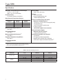
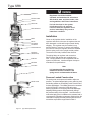
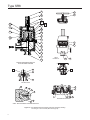
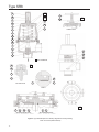
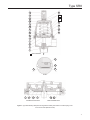
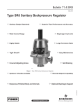
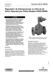
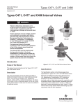
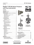
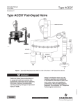
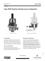
Type SR8
Instruction Manual
Form 5787
February 2006
Type SR8 Sanitary Backpressure Regulator
Inlet PRessure
Outlet PRessure
Atmospheric PRessure
W8967
Figure 1. Type SR8
Figure 2. Operational Schematic
Introduction
Principle of Operation
Type SR8 self contained backpressure regulators
are suitable for pressure control of steam, liquid, or
gaseous service. Typical set points range from 2 to
125 psi (0,2 to 8,6 bar). The regulator is designed to
meet sanitary application and material requirements.
Pressure in the controlled system (regulator inlet
pressure) registers beneath the diaphragm of the
regulator and opposes the force provided by the
predetermined spring compression. When regulator
spring force exceeds diaphragm force exerted by
the inlet pressure, the spring will keep the valve plug
closed to prevent flow to the downstream system. As
inlet pressure increases above setpoint, this increase
registers on the diaphragm and the valve plug opens
to allow flow to the downstream system.
Scope of the Manual
D103100X012
This manual provides installation, startup,
maintenance, and parts ordering information for the
Type SR8 Sanitary Backpressure Regulator.
Patents Pending
R
www.emersonprocess.com/regulators
Type SR8
Specifications
Body Size, Inlet and Outlet Connection Style
1/2, 3/4, 1, 1-1/2, 2, and 3
(DN 15, 20, 25, 40, 50 and 80)
End Connection(4)
Tri-Clamp ® Sanitary connections
Body Pressure/Temperature Ratings(1)
MAXIMUM
TEMPERATURE ,
°F (°C)
MAXIMUM INLET
PRESSURE,
PSIG (bar)
MAXIMUM OUTLET
PRESSURE,
PSIG (bar)
150 (65)
210 (14,5)
210 (14,5)
275 (135)
180 (12,4)
180 (12,4)
400 (204)
160 (11)
160 (11)
Options
Vacuum protection
Pressure loaded spring case
T-handle adjusting screw
Pressure Loaded Spring Case Option
Maximum Loading Pressure
1/2 through 1-1/2-inch (DN 15 through 40) body:
125 psig (8,62 bar)
2 and 3-inch (DN 50 and 80) body:
60 psig (4,14 bar)
1/4-inch NPT tapped vent connection
Maximum Operating Pressures(1, 3)
See Table 1
Vacuum Protection Option
Set Pressure Ranges
See Table 2
Maximum Vacuum Pressure
14 psig (0,96 bar) (vacuum)
Maximum Differential Pressures(1)
See Table 3
Certifications Available upon Request
3A certificate
FDA approved elastomers/plastics
Material and Functional Test Certificates
USP Class VI approved elastomers/plastics(2)
Regulator Temperature Capabilities(1)
See Table 4
Pressure Registration
Internal
1.
2.
3.
4.
Service Media
Steam, Gas, and Liquid
The pressure/temperature limits in this manual and any applicable standard or code limitation should not be exceeded.
Contact your Fisher Sales Representative for details on available constructions.
Maximum pressure to prevent damage to internal parts and leakage to atmosphere.
End connection clamps and gaskets to be supplied by the user.
Table 1. Maximum Operating Pressures
BODY SIZE,
INCHES (dN)
1/2, 3/4, 1, 1-1/2
(15, 20, 25, 40)
2 and 3
(50 and 80)
Maximum Temperature,
°F (°C)
Maximum Inlet Pressure,
psig (bar)
Maximum Outlet Pressure,
psig (bar)
150
(65)
210
(14,5)
210
(14,5)
275
(135)
180
(12,4)
180
(12,4)
400
(204)
160
(11)
160
(11)
150
(65)
150
(10,3)
150
(10,3)
275
(135)
125
(8,62)
125
(8,62)
400
(204)
110
(7,58)
110
(7,58)
Type SR8
Table 2. Set Pressure Ranges and Control Spring Data
Body Size,
inches (DN)
Set Pressure Ranges,
psig (bar)
1/2, 3/4
(15, 20)
Color
Wire Diameter,
Inch (mm)
Free Length,
Inch (mm)
Part Number
2 to 8
(0,2 to 0,5)
Blue
0.138 (3,51)
2.75 (69,9)
GE06780X012
5 to 25
(0,4 to 1,7)
Silver
0.177 (4,50)
2.75 (69,9)
GE06781X012
10 to 50
(0,7 to 3,4)
Green
0.192 (4,88)
2.75 (69,9)
GE06782X012
35 to 100
(2,4 to 6,9)
Red
0.225 (5,72)
2.75 (69,9)
GE06783X012
(5,2 to 8,6)
Red/
Yellow
0.225 (5,72)/
0.148 (3,76)
2.75 (69,9)/
2.75 (69,9)
GE06783X012/
GE06784X012
75 to 125
2 to 8
(1)
(0,2 to 0,5) (1)
Blue
0.225 (5,72)
3.25 (82,6)
GE02763X012
5 to 25
(0,4 to 1,7)
Silver
0.282 (7,16)
3.25 (82,6)
GE02764X012
15 to 70
(1,0 to 4,8)
Green
0.331 (8,41)
3.25 (82,6)
GE02765X012
25 to 90
(1,7 to 6,2)
Red
0.362 (9,19)
3.25 (82,6)
GE02766X012
35 to 100
(2,4 to 6,9)
Green
Yellow
0.331 (8,41)
0.250 (6,35)
3.25 (82,6)
3.25 (82,6)
GE02765X012
GE06090X012
75 to 125
(5,2 to 8,6)
Red/
Yellow
0.362 (9,19)/
0.250 (6,35)
3.25 (82,6)/
3.25 (82,6)
GE02766X012/
GE06090X012
10 to 25
(0,7 to 1,7)
Silver
0.562 (14,3)
6.00 (152,4)
GE14003X012
15 to 50
(1,0 to 3,4)
Green
0.625 (15,9)
6.00 (152,4)
GE14004X012
25 to 60
(1,7 to 4,1)
Red
0.625 (15,9)
6.00 (152,4)
GE14005X012
1, 1-1/2 (25, 40) full port
1-1/2 x 1 (40 x 25)
2 and 3
(50 and 80)
1. The 2 to 8 psig (0,14 to 0,55 bar) spring is not available with the metal diaphragm.
Table 3. Maximum Differential Pressures
Body Size, Inches (DN)
1/2, 3/4
(15, 20)
1, 1-1/2 (25, 40) full port
1-1/2 x 1 (40 x 25)
2 and 3
(50 and 80)
Outlet Pressure
Ranges, Psig (bar)
Color
Maximum Differential
Pressure, psiD (bar d)
2 to 8
(0,2 to 0,5)
Blue
15
(1,0)
5 to 25
(0,4 to 1,7)
Silver
40
(2,7)
10 to 50
(0,7 to 3,4)
Green
100
(6,9)
35 to 100
(2,4 to 6,9)
Red
140
(9,6)
75 to 125
(5,2 to 8,6)
Red/Yellow
160
(11)
2 to 8
(0,2 to 0,5)
Blue
15
(1,0)
5 to 25
(0,4 to 1,7)
Silver
40
(2,7)
15 to 70
(1,0 to 4,8)
Green
100
(6,9)
25 to 90
(1,7 to 6,2)
Red
125
(8,6)
35 to 100
(2,4 to 6,9)
Green/Yellow
140
(9,6)
75 to 125
(5,2 to 8,6)
Red/Yellow
160
(11)
10 to 25
(0,7 to 1,7)
Silver
50
(3,4)
15 to 50
(1,0 to 3,4)
Green
75
(5,2)
25 to 60
(1,7 to 4,1)
Red
75
(5,2)
Table 4. Temperature Capabilities
Seat Type
Metal (316L)
Soft (PTFE/316L)
Soft (PEEK/316L)
Diaphragm Material
O-Ring Material
EPDM
EPDM
Temperature Range, °F (°C)
- 20 to 275
( -28 to 135)
316L SST
PTFE/FKM (1)
+20 to 400
( -6 to 204)
PTFE/FKM
PTFE/FKM
+20 to 400
( -6 to 204)
EPDM
EPDM
- 20 to 150
( -28 to 65)
316L SST
PTFE/FKM (1)
+20 to 150
( -6 to 65)
PTFE/FKM
PTFE/FKM
+20 to 150
( -6 to 65)
EPDM
EPDM
-20 to 275
(-28 to 135)
316L SST
PTFE/FKM (1)
+20 to 400
(-6 to 204)
PTFE/FKM
PTFE/FKM
+20 to 400
(-6 to 204)
1. O-ring material is PTFE for the 1/2 and 3/4 inch (DN 15 and 20) sizes. Temperature range is the same.
Type SR8
Closing Cap
Adjusting Screw
LockNut
Spring Case
Upper Spring Seat
Spring
Hex Nut
Split washer
Flat Washer
Lower Spring Seat
Piston Ring
(spring side up)
Guide Ring
Diaphragm
Plug O-Ring
Plug
Regulators should be installed,
operated, and maintained in accordance
with federal, state, and local codes, rules
and regulations, and Fisher instructions.
If a leak develops in the system,
it indicates service is required.
Failure to take the regulator out of
service immediately may create a
hazardous condition.
Installation
Clean out all pipelines before installation of the
regulator and check to be sure the regulator has not
been damaged or collected foreign material during
shipping. The regulator may be installed in any
position desired. However, to ensure self-draining
(from inlet to outlet) the regulator should be installed
with the spring case in the upright vertical position.
The arrow on the body indicates flow direction.
The piping flange to regulator end connection
flange clamps and gaskets are supplied by the
user. Clamp gaskets must be compatible with the
system requirements. Install and tighten clamps to
manufacturer’s specifications.
Note
It is important that the regulator be
installed so that the vent hole in the
spring case is unobstructed at all times.
Pressure Loaded Construction
Sanitary Clamp
Body
Figure 3. Type SR8 Exploded View
The spring case can be pressure loaded to adjust set
pressure. An optional tapped spring case, guide ring seal,
and sealing washer on the adjusting screw must be used
for these applications. The loading pressure is connected
to the 1/4-inch NPT connection in the spring case
allowing registration on the spring side of the diaphragm.
Adjusting loading pressure will proportionally change
the pressure setting of the regulator. A small amount of
mechanical spring load, in addition to the pressure load, is
recommended. Regulator set pressure achieved from the
combination of spring load and pressure load should not
exceed the set pressure ranges listed in Table 2.
Type SR8
Maintenance
Over pressuring any portion of this
equipment may result in equipment
damage, leaks in the valve, or personal
injury due to bursting of pressurecontaining parts. The system should be
inspected after any overpressure condition.
Startup
The regulator is factory set to the midpoint of the
spring range. Please refer to the Adjustment section
for directions on changing the setpoint. With proper
installation completed, slowly open the upstream and
downstream shutoff valves.
Note
When the pressure load option is used,
always open block valves on main line
before applying loading pressure to the
spring case to avoid diaphragm damage.
Adjustment
The setting of the regulator can be varied within the
pressure range stamped on the nameplate. Setpoint is
defined as the point the regulator starts to open. Build
up above setpoint is required to achieve maximum
capacity. To change the setpoint, loosen the locknut
(key 17, Figure 4) or locking lever (key 22, Figure 4) and
turn the adjusting screw (key 18, Figure 4) clockwise to
increase the setpoint, or counterclockwise to decrease
it. Monitor the inlet pressure with a test gauge during
the adjustment. Tighten the locknut or locking lever to
maintain the desired setting. Available set pressure
ranges, recommended maximum allowable differential
pressures and spring data are shown in Tables 2 and 3.
Shutdown
Close the upstream shutoff valve. Close downstream
shutoff valve. Open the applicable bleed valves to
exhaust the system.
Note
When the pressure loaded option is
used, bleed all pressure from the spring
case before bleeding pressure under the
diaphragm to avoid internal part damage.
Before disassembling the regulator,
isolate it from the pressure system and
release all pressure from the regulator
as specified in the Shutdown section.
Relieve all spring compression and isolate
regulator from the pressurized system
prior to removing the clamp (key 15).
Due to normal wear that may occur, parts must be
periodically inspected and replaced if necessary.
The frequency of inspection depends on the severity
of service conditions. A Preventative Maintenance
schedule should be implemented that checks regulator
set point and lockup and that evaluates regulator
performance to the system requirements. Regulator
performance outside the system requirements will
require either adjustment, part maintenance or
regulator replacement to meet system requirements.
This section includes instructions for disassembly
and replacement of parts. All key numbers refer to
Figure 4 or 5.
1. If damage to the diaphragm or seating surface is
suspected, or to inspect other internal parts, loosen
the locknut (key 17) or locking lever (key 22) and
turn the adjusting screw (key 18) counterclockwise to
remove all spring compression.
2. Loosen the sanitary clamp (key 15) to remove the
spring case (key 14). Remove the upper spring seat
(key 11) and the regulator spring (keys 12 and 13,
when applicable).
3. Remove the diaphragm assembly and plug from
the body (key 1). Inspect parts for damage.
Note
When disassembling a unit with a metal
diaphragm, replace both diaphragm
gaskets (key 6) to ensure a good seal at
the diaphragm flange.
Replace the piston ring (key 5), if it has
been removed from the guide ring (key 9).
Take care not to damage the piston ring
during replacement.
4. If parts require replacement, loosen the nut (key 16)
while holding wrench flats on plug (key 3) and remove
the lock washer (key 24) and flat washer (key 23). The
lower spring seat (key 8), guide ring (key 9), diaphragm
Type SR8
19
18
18
22
17
33
11
16
12
34
T-Handle Option
24
14
23
8
13
9
21
5
29
15
7
3
2
1
view a
rotated 180°
standard Backpressure Regulator
with Elastomeric Diaphragm
29
20
A
A
26
35
35
33
28
27
soft seat option
15
15
14
14
8
9
9
9
6
6
77
7
1
1
66
3
View b – Metal Diaphragm for standard Regulator
Figure 4. Type SR8 Backpressure Sanitary Regulator Assembly Drawing
1/2 through 1-1/2-Inch Sizes (DN 15 through 40)
10
vacuum protection option
4
Type SR8
32
6
19
33
11
12
18
7
17
25
34
14
16
13
24
32
23
6
view b
8
9
5
15
7
b
3
2
7
1
3
metal diaphragm option
Figure 5. Type SR8 Sanitary Backpressure Regulator Assembly with Pressure Loaded Spring Case
1/2 through 1-1/2-Inch Sizes (DN 15 through 40)
(key 7), and plug O-ring (key 3) can now be removed
from the plug (key 2). An optional lower diaphragm
plate (key 10) and O-ring (key 4) are included for the
constructions offering protection against
vacuum conditions.
5. Replace any damaged parts. Refer to the
section titled Soft Seat Maintenance when the seat
needs to be replaced.
6. Reassemble in the reverse order of the above
procedure. The order is listed below or refer to Figure 3.
a.) Plug (key 2)
b.) Plug O-ring (key 3)
c.) Diaphragm plate (key 10) (vacuum protection
construction only)
d.) Diaphragm plate O-ring (key 4) (vacuum
protection construction only)
e.) Diaphragm gasket (key 6) (Metal diaphragms only)
f.) Diaphragm (key 7)
g.) Diaphragm gasket (key 6) (Metal diaphragms only)
h.) Guide ring assembly (keys 9 and 5)
i.) Lower spring seat (key 8)
j.) Flat Washer (key 23)
k.) Lock Washer (key 24)
l.) Hex Nut (key 16)
7. Hold wrench flats on plug (key 2), then torque hex
nut (key 16) to 6 to 8 in•lbs (0,7 to 0,9 N•m) for the
1/2 and 3/4-inch (DN 15 and 20), 5 to 7 ft-lbs (7 to 9
N•m) for the 1 and 1-1/2 inch (DN 25 and 40) and 28
to 30 ft-lbs (38 to 41 N•m) for 2 and 3-inch (DN 50 and
80). After tightening the hex nut, apply Loctite 290 or
equivalent to the nut/thread interface.
8. Position diaphragm assembly in body (key 1).
Replace regulator spring (keys 12 and 13, when
applicable) and upper spring seat (key 11). Replace
the spring case (key 14) and sanitary clamp (key 15).
Torque clamp nuts to 20 to 22 ft•lbs (27 to 30 N•m) for
the 1/2 through 1-1/2-inch (DN 15 through 40) and 38
to 40 ft•lbs (52 to 54 N•m) for the 2 and 3-inch (DN 50
and 80).
Type SR8
Note
Lubricate the adjusting screw (key 18)
threads and the sanitary clamp bolt threads
(key 15) to reduce galling of stainless steel.
Factory recommends Bostik Never Seez
white food grade lubricant.
Keep even spacing between clamp halves
when tightening clamp nuts. This will
ensure even loading of the diaphragm. If
clamp halves touch, please contact factory
for a replacement clamp.
9. Follow Startup and Adjustment procedures.
Soft Seat Maintenance
Take care not to damage the internal/wetted surface
finish when performing Soft Seat Maintenance.
1. Disassemble the regulator as stated in the
prior section.
2. To access soft seat (key 28), unscrew the
lower plug (key 27) from the upper plug (key 26). If
damaged, replace with new part. Apply Loctite 246 or
equivalent to male thread before tightening. Proper
torque for the assembly is 6 to 8 in•lbs (0,7 to 0,9 N•m)
for the 1/2-inch and 3/4-inch (DN 15 and 20); 8 to
10 in•lbs (0,9 to 1,1 N•m) for the 1-inch and 1-1/2 x 1-inch
(DN 25 and 40 x 25); and 5 to 7 ft•lbs (7 to 9 N•m) for the
1-1/2 inch (DN 40). Torque for 2 and 3-inch (DN 50 and
80) is 23 to 25 ft•lbs (31 to 34 N•m).
3. Reassemble as stated in the prior section.
Parts Ordering
When corresponding with your Fisher sales office or
sales representative about this equipment, always
reference the equipment serial number and FS
number that can be found on the nameplate.
When ordering replacement parts, reference the key
number of each needed part as found in the following
parts list. Separate kits containing all recommended
spare parts are available.
Parts List
Key Description
Part Number
Parts Kits
Diaphragm Kits (includes keys 3, 5, and 7. Stainless steel kits
include key 6, qty 2) Does not include all applicable parts for
changing between elastomer and metal diaphragm constructions.
See parts list for differences.
1/2 and 3/4-inch (DN 15 and 20) bodies
EPDM diaphragm and O-ring RSR58X00E12
316L SST Diaphragm and PTFE/FKM O-rings RSR58X00S12
PTFE/FKM Diaphragm and O-rings
RSR58X00V12
1 and 1-1/2-inch (DN 25 and 40) bodies
EPDM diaphragm and O-rings RSR58X00E22
316L SST Diaphragm and PTFE/FKM O-rings RSR58X00S22
PTFE/FKM Diaphragm and O-rings
RSR58X00V22
2 and 3-inch (DN 50 and 80) bodies
EPDM diaphragm and O-rings
RSR58X00E32
316L SST Diaphragm and PTFE/FKM O-rings
RSR58X00S32
Soft Seat Kits (includes keys 26, 27, and 28)
1/2-Inch (DN 15) body
PTFE/316L SST
GE06788X012
PEEK/316L SST
GE06788X022
3/4-Inch (DN 20) body
PTFE/316L SST
GE06797X012
PEEK/316L SST
GE06797X022
1-Inch (DN 25) body
PTFE/316L SST
GE06323X012
PEEK/316L SST
GE06323X022
1-1/2-Inch (DN 40) body
PTFE/316L SST
GE06324X012
PEEK/316L SST
GE06324X022
2 and 3-Inch (DN 50 and 80) bodies
PTFE/316L SST
GE14009X012
PEEK/316L SST
GE14009X022
1
Body
1/2-Inch (DN 15) body
GE07951X012
3/4-Inch (DN 20) body
GE07952X012
1-Inch (DN 25) body GE07949X012
1-1/2 Inch (DN 40) body GE07950X012
1-1/2 x 1-Inch (DN 40 x 25) body
GE07776X012
2-Inch (DN 50) body
GE13988X012
3-Inch (DN 80) body
GE13989X012
2
Plug (metal seat)
1/2-Inch (DN 15) body
GE06786X012
3/4-Inch (DN 20) body
GE06795X012
1-Inch and 1-1/2 x 1-Inch
(DN 25 and 40 x 25) bodies
GE06039X012
1-1/2 Inch (DN 40) body
GE06191X012
2 and 3-Inch (DN 50 and 80) bodies
GE14007X012
3
Plug O-Ring
1/2 and 3/4-Inch (DN 15 and 20) bodies
Elastomer diaphragms
EPDM
1H2919X0022
PTFE/FKM
1P8453X0042
316L Stainless Steel diaphragms
PTFE
GE10788X012
EPDM
14B1935X032
1 and 1-1/2 Inch (DN 25 and 40) bodies
Elastomer diaphragms
EPDM
1D2888X0042
PTFE/FKM
1C7822X0142
316L Stainless Steel diaphragms
PTFE/FKM
16A6903X022
EPDM
14A1968X042
Type SR8
Key Description
Part Number
3
Plug O-Ring (continued)
2 and 3-Inch (DN 50 and 80) bodies
Elastomer diaphragms
EPDM
1B8855X0112
PTFE/FKM
12A0006X022
316L Stainless Steel diaphragms
PTFE/FKM
12A0006X022
EPDM
1B8855X0112
4
Diaphragm Plate O-Ring
1/2 and 3/4-inch (DN 15 and 20) bodies
EPDM
1W1932X0082
PTFE/FKM
1W1932X0092
1 and 1-1/2-inch (DN 25 and 40) bodies
EPDM 1V3234X0042
PTFE/FKM
1V3234X0052
2 and 3-Inch (DN 50 and 80) bodies
EPDM
1V3303X0082
PTFE/FKM
1V3303X0092
5
Piston Ring 1/2 and 3/4-Inch (DN 15 and 20) bodies
GE09274X012
1 and 1-1/2 Inch (DN 25 and 40) bodies
GE09273X012
2 and 3-Inch (DN 50 and 80) bodies
GE14027X012
6
Diaphragm Gasket, for use with 316L Stainless steel
diaphragm only, PTFE (2 required)
1/2 and 3/4-inch (DN 15 and 20) bodies
GE06772X012
1 and 1-1/2-inch (DN 25 and 40) bodies
GE06076X012
2 and 3-Inch (DN 50 and 80) bodies
GE13995X012
7
Diaphragm
1/2 and 3/4-inch (DN 15 and 20) bodies
EPDM
GE06778X012
316L SST
GE06777X012
PTFE/FKM
GE06779X012
1 and 1-1/2-inch (DN 25 and 40) bodies
EPDM
GE02299X012
316L SST
GE02643X012
PTFE/FKM
GE06086X012
2 and 3-Inch (DN 50 and 80) bodies
EPDM
GE14001X012
316L SST
GE14000X012
8
Lower Spring Seat
1/2 and 3/4-inch (DN 15 and 20) bodies
Without Vacuum Protection
GE06774X012
With Vacuum Protection
GE06775X012
1, 1-1/2, and 1-1/2 x 1-Inch
(DN 25, 40, and 40 x 25) bodies
Without Vacuum Protection
GE06330X012
With Vacuum Protection
GE02638X012
2 and 3-Inch (DN 50 and 80) bodies
Without Vacuum Protection
GE13997X012
With Vacuum Protection
GE13998X012
9
Guide Ring
1/2 and 3/4-inch (DN 15 and 20) bodies
GE06770X012
1 and 1-1/2-inch (DN 25 and 40) bodies
GE02637X012
2 and 3-Inch (DN 50 and 80) bodies
GE13994X012
10
Diaphragm Plate
1/2 and 3/4-inch (DN 15 and 20) bodies
GE06776X012
1, 1-1/2, and 1-1/2 x 1-Inch
(DN 25, 40, and 40 x 25) bodies
GE02642X012
2 and 3-Inch (DN 50 and 80) bodies
GE13999X012
11
Upper Spring Seat
1/2 and 3/4-inch (DN 15 and 20) bodies
GE06773X012
1, 1-1/2 and 1-1/2 x 1-Inch
(DN 25, 40 and 40 x 25) bodies
GE02639X012
2 and 3-inch (DN 50 and 80) bodies
GE13996X012
12
Spring
See Table 2
13
Spring
1/2 and 3/4-inch (DN 15 and 20) bodies
GE06784X012
1, 1-1/2, and 1-1/2 x 1-Inch
(DN 25, 40, and 40 x 25) bodies
GE06090X012
Key Description
Part Number
14
Spring Case
1/2 and 3/4-inch (DN 15 and 20) bodies
CF8M Standard
GE06767X012
Pressure Loaded
GE06768X012
316 SST
Standard
GE17730X012
Pressure Loaded
GE14020X012
1 and 1-1/2-inch (DN 25 and 40) bodies
CF8M
Standard
GE02641X012
Pressure Loaded
GE06118X012
316 SST
Standard
GE17755X012
Pressure Loaded
GE14021X012
2 and 3-inch (DN 50 and 80) bodies
CF8M Standard
GE13992X012
Pressure Loaded GE13991X012
316 SST
Standard
GE14018X012
Pressure Loaded
GE14019X012
15
Bolted Clamp
1/2 and 3/4-inch (DN 15 and 20) bodies
GE06769X012
1 and 1-1/2-inch (DN 25 and 40) bodies
GE06116X012
2 and 3-inch (DN 50 and 80) bodies
GE13993X012
16
Hex Nut
1/2 and 3/4-inch (DN 15 and 20) bodies
10A1341X022
1 and 1-1/2-inch (DN 25 and 40) bodies
1A309338992
2 and 3-inch (DN 50 and 80) bodies
T1208735252
17
Hex Nut
1/2 and 3/4-inch (DN 15 and 20) bodies
1A3465X0032
1 and 1-1/2-inch (DN 25 and 40) bodies
T1208635252
2 and 3-inch (DN 50 and 80) bodies
1A3511X0072
18
Adjusting Screw
1/2 and 3/4-inch (DN 15 and 20) bodies
Standard
GE08849X012
T-Handle
GE08987X012
1 and 1-1/2-inch (DN 25 and 40) bodies
Standard
GE06080X012
T-Handle
GE08985X012
2 and 3-inch (DN 50 and 80) bodies
Standard
GE14024X012
T-Handle
GE14025X012
19
Closing Cap
1/2, 3/4, 1 and 1-1/2-inch (DN 15, 20, 25 and 40) bodies
316 SST
1E5433X0032
Plastic
20B3082X012
2 and 3-inch (DN 50 and 80) bodies
GE14028X012
20
Flow Arrow
1V105938982
21
Nameplate
----------22
Locking Lever
1/2 and 3/4-inch (DN 15 and 20) bodies
GE08989X012
1 and 1-1/2-inch (DN 25 and 40) bodies
GE08988X012
2 and 3-inch (DN 50 and 80) bodies
GE14026X012
23
Flat Washer
1/2 and 3/4-inch (DN 15 and 20) bodies
1C3329X0022
1 and 1-1/2-inch (DN 25 and 40) bodies
GC060805X22
2 and 3-inch (DN 50 and 80) bodies
1A5189X0022
24
Lock Washer
1/2 and 3/4-inch (DN 15 and 20) bodies
1H3395X0012
1 and 1-1/2-inch (DN 25 and 40) bodies
1C2257K0012
2 and 3-inch (DN 50 and 80) bodies
1A639638992
25
Sealing Washer
1/2 and 3/4-inch (DN 15 and 20) bodies
12A3880X022
1 and 1-1/2-inch (DN 25 and 40) bodies
GE20712X012
2 and 3-inch (DN 50 and 80) bodies
1V4246X0022
Type SR8
19
33
18
34
17
18
16
14
33
22
24
11
23
12
T-Handle Option
8
9
5
15
7
3
21
2
29
1
20
APPLY LUB SEALANT
35
26
28
1
27
6
6
7
soft seat option
DETAIL A
A
33
7
4
10
3
vacuum protection option
3
7
metal diaphragm option
Figure 6. Type SR8 Backpressure Sanitary Regulator Assembly Drawing
2 and 3-Inch Sizes (DN 50 and 80)
10
Type SR8
19
25
18
33
17
34
14
16
11
24
12
8
23
9
32
5
15
7
3
2
1
APPLY LUB SEALANT
32
6
6
7
DETAIL A
A
7
4
10
3
vacuum protection option
3
7
metal diaphragm option
Figure 7. Type SR8 Sanitary Backpressure Regulator Assembly with Pressure Loaded Spring Case
2 and 3-Inch Sizes (DN 50 and 80)
11
Type SR8
Key Description
26
Upper Plug
1/2-Inch (DN 15) body
3/4-Inch (DN 20) body
1 and 1-1/2 x 1-Inch (DN 25 and 40 x 25) bodies
1-1/2 Inch (DN 40) body
2 and 3-inch (DN 50 and 80) bodies 27
Lower Plug
1/2-Inch (DN 15) body
3/4-Inch (DN 20) body
1 and 1-1/2 x 1-Inch (DN 25 and 40 x 25) bodies
1-1/2 Inch (DN 40) body
2 and 3-inch (DN 50 and 80) bodies
28 Soft Seat
1/2-Inch (DN 15) body
PTFE
PEEK
3/4-Inch (DN 20) body
PTFE
PEEK
Part Number
GE06792X012
GE06801X012
GE06325X012
GE06326X012
GE14013X012
GE06793X012
GE06802X012
GE06327X012
GE06328X012
GE14014X012
GE06789X012
GE06789X022
GE06798X012
GE06798X022
Key Description
Part Number
28 Soft Seat (continued)
1 and 1-1/2 x 1-Inch (DN 25 and 40 x 25) bodies
PTFE
GE06197X012
PEEK
GE06197X022
1-1/2 Inch (DN 40) body
PTFE
GE06200X012
PEEK
GE06200X022
2 and 3-inch (DN 50 and 80) bodies
PTFE
GE14010X012
PEEK
GE14010X022
29
Drive Screw (2 required)
1E953028982
32
Guide Ring Seal
1/2 and 3/4-Inch (DN 15 and 20) bodies
GE18400X012
1 and 1-1/2 Inch (DN 25 and 40) bodies
GE18399X012
2 and 3-inch (DN 50 and 80) bodies GE11039X012
33
Bostik Never Seez Food Grade
(white) or equivalent
----------34
Loctite 290 or equivalent
----------35
Loctite 246 or equivalent
-----------
Industrial
Natural Gas Technologies
Industrial/High Purity
USA - Headquarters
McKinney, Texas 75070 USA
Tel: 1-800-558-5856
Outside U.S. 1-469-293-4201
USA - Headquarters
McKinney, Texas 75070
Tel: 1-800-558-5856
Outside U.S. 1-469-293-4201
Asia-Pacific
Shanghai, China 201206
Tel: 86-21-5899 7887
Asia-Pacific
Singapore, Singapore 128461
Tel: +65 6777 8211
TESCOM
Elk River, Minnesota 55330 USA
Tel: 1-763-241-3238
Selmsdorf, Germany 23923
Tel: +49 (0) 38823 31 0
Europe
Bologna, Italy 40013
Tel: 39 051 4190611
Europe
Bologna, Italy 40013
Tel: 39 051 4190611
Gallardon, France 28320
Tel: +33 (0)2 37 33 47 00
For further information visit www.emersonprocess.com/regulators
The Emerson logo is a trademark and service mark of Emerson Electric Co. All other marks are the property of their prospective owners. Fisher is a mark owned by Fisher Controls, Inc., a
business of Emerson Process Management.
The contents of this publication are presented for informational purposes only, and while every effort has been made to ensure their accuracy, they are not to be construed as warranties or
guarantees, express or implied, regarding the products or services described herein or their use or applicability. We reserve the right to modify or improve the designs or specifications of such
products at any time without notice.
Emerson Process Management does not assume responsibility for the selection, use or maintenance of any product. Responsibility for proper selection, use and maintenance of any Emerson
Process Management product remains solely with the purchaser.
©Fisher Controls International, Inc., 2004, 2006; All Rights Reserved