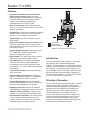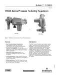
1
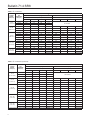
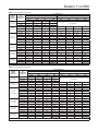
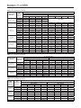
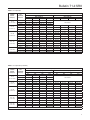
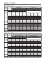
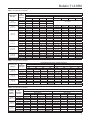
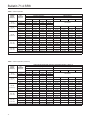
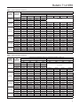
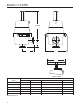
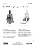
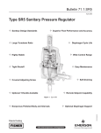
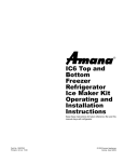
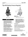
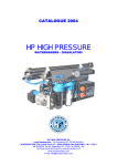
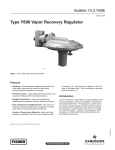
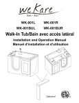
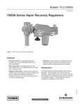
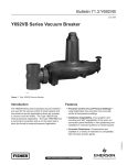
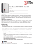
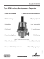
Bulletin 71.4:SR8 May 2010 Type SR8 Sanitary Backpressure Regulator Sanitary Design Standards Superior Flow Performance and Accuracy Wide Control Range Diaphragm Cycle Life Highly Stable Large Turndown Ratio Tight Shutoff Easy Maintenance Covered Adjusting Screw Self-Draining W8967 Figure 1. Type SR8 Sanitary Backpressure Regulator Optional T-Handle Available Remote Setpoint Capability Optional Diaphragm Support D103106X012 Nonporous Polished Body and Internals www.fisherregulators.com Bulletin 71.4:SR8 Features • Nonporous Polished Body and Internals for High Purity Processing—Body, plug, and diaphragm plate (when applicable) are machined from 316L Stainless steel. All internal wetted surfaces are mechanically polished and electropolished to 20 µin (0,5 µm) Ra. • Wide Control Range—Typical setpoints range from 2 to 125 psig (0,14 to 8,6 bar) to cover a wide range of applications. • Self-Draining—Fluids will drain toward the outlet of the body when the regulator is installed with the spring case in the upright vertical position. • Tight Shutoff—Soft seat is available to ensure better shutoff. • Superior Flow Performance and Accuracy—The Type SR8 is designed to deliver high flows with minimal buildup to maintain an even pressure over the full range of flow. • Sanitary Design Standards—Designed to meet 3A®, ASME BPE, and European Hygienic Equipment Design Group criteria. • Highly Stable—The upper guide ring provides for stable control over entire operating range. • Easy Maintenance—The design incorporates a metal-to-metal stop to protect diaphragms from damage due to over compression at outer circumference. Tri-Clamp® allows easy access to internal parts. • Large Turndown Ratio—No need for reduced Cv trims at low flows. • Optional Diaphragm Support—A diaphragm support is added to the regulator for installations that will be exposed to vacuum conditions. • Covered Adjusting Screw—Electropolished stainless steel adjusting screw cover improves the aesthetics and cleanability of the regulator. • Diaphragm Cycle Life—Metal 316L Stainless steel diaphragm is designed to maximize service life. • Optional T-Handle Available—T-Handle option available to accommodate frequent adjustments. • Remote Setpoint Capability—An optional spring case configuration permits pressure loading. Loading pressure varied from a remote location adjusts the setpoint in direct proportion. Tri-Clamp® is a mark owned by Tri-Clover, Incorporated. 3-A® is a mark owned by 3-A Sanitary Standards, Incorporated. 2 Inlet PRessure Outlet Pressure Atmospheric Pressure Figure 2. Type SR8 Operational Schematic Introduction The Type SR8 backpressure regulator is a compact, large capacity, direct-operated backpressure regulator. It is designed for use in applications where a sanitary design is essential, such as pharmaceutical, biotechnology, or food and beverage industries. The unit is available in NPS 1/2 through 3 (DN 15 through 80) sizes with end connections that will match up to Tri-Clamp® sanitary fittings. The Type SR8 is suitable for use in steam, liquid, or gas service. Principle of Operation The Type SR8 is a direct-operated regulator. Pressure in the controlled system (regulator inlet pressure) registers beneath the diaphragm of the regulator and opposes the force provided by the predetermined spring compression. When regulator spring force exceeds diaphragm force exerted by the inlet pressure, the spring will keep the valve plug closed to prevent flow to the downstream system. As inlet pressure increases above setpoint, this increase registers on the diaphragm and the valve plug opens to allow flow to the downstream system. Bulletin 71.4:SR8 Specifications Body Size, Inlet and Outlet Connection NPS 1/2, 3/4, 1, 1-1/2, 2 and 3 (DN 15, 20, 25, 40, 50 and 80) Service Media All Sizes: Steam, Gas, and Liquid End Connection Tri-Clamp® Sanitary connections(5) Body Pressure/Temperature Ratings(1) Maximum Temperature, °F (°C) Maximum Inlet Pressure, psig (bar) Maximum Outlet Pressure, psig (bar) 150 (65) 210 (14,5) 210 (14,5) 275 (135) 180 (12,4) 180 (12,4) 400 (204) 160 (11,0) 160 (11,0) Maximum Operating Pressures(1)(3) Body Size, NPS (Dn) Maximum Temp, °F (°C) Max Inlet Pressure, psig (bar) Max Outlet Pressure, psig (bar) 1/2 through 1-1/2 (DN 15 through 40) 150 (65) 210 (14,5) 210 (14,5) 275 (135) 180 (12,4) 180 (12,4) 400 (204) 160 (11,0) 160 (11,0) 150 (65) 150 (10,3) 150 (10,3) 275 (135) 125 (8,6) 125 (8,6) 400 (204) 110 (7,6) 110 (7,6) 2 and 3 (DN 50 and 80) Set Pressure Ranges See Table 1 Maximum Differential Pressures(1) See Table 1 Temperature Capabilities(1) See Table 2 Flow Coefficients See Table 4 Construction Materials See Table 3 Pressure Registration Internal Pressure Loaded Spring Case Option Maximum Loading Pressure NPS 1/2 through 1-1/2 (DN 15 to 40) body: 125 psig (8,6 bar) NPS 2 and 3 (DN 50 and 80) body: 60 psig (4,1 bar) 1/4 NPT Tapped Vent Connection Vacuum Protection Option Maximum Vacuum Pressure 14 psig (1,0 bar) (vacuum) Certifications Available Upon Request 3A® certificate (Ethylenepropylene (EPDM) and 316L Stainless steel diaphragms only) FDA approved elastomers/plastics Material and Functional Test Certificates USP Class VI approved elastomers/plastics(2) Spring Case Construction Drilled untapped vent holes (standard) 1/4 NPT for Pressure Load Connection (optional) Pressure Setting Adjustment Adjusting screw with Electropolished Cover (standard) T-Handle adjusting screw (optional) Shutoff Classification per ANSI/FCI 70-3-2003 Metal Seat: ANSI Class III Polytetrafluoroethylene (PTFE) Soft Seat: ANSI Class VI Polyetheretherketone (PEEK) Soft Seat: ANSI Class VI (150-400°F)(4) Approximate Weight NPS 1/2 and 3/4 (DN 15 and 20): 9 pounds (4 kg) NPS 1 and 1-1/2 (DN 25 and 40): 18 pounds (8 kg) NPS 2 and 3 (DN 50 and 80): 60 pounds (27 kg) Options Vacuum protection Pressure Loaded spring case T-handle adjusting screw 1. The pressure/temperature limits in this bulletin and any applicable standard or code limitation should not be exceeded. 2. Contact your Local Sales Office for details on available constructions. 3. Maximum pressure to prevent damage to internal parts and leakage to atmosphere. 4. Polyetheretherketone (PEEK) Seat meets ANSI Class IV or better below 150°F (66°C). 5. End connection clamps and gaskets to be supplied by the user. Tri-Clamp® is a mark owned by Tri-Clover, Incorporated. 3-A® is a mark owned by 3-A Sanitary Standards, Incorporated. 3 Bulletin 71.4:SR8 Table 1. Set Pressure Ranges, Control Spring Data, and Maximum Differential Pressures Body Size, nps (DN) Set Pressure Ranges, psig (bar) 2 to 8 (0,14 to 0,55)(1) 1/2 and 3/4 (15 and 20) Color Code Part Number Wire Diameter, Inch (mm) Free Length, Inch (mm) 15 (1,0) Blue GE06780X012 0.138 (3,51) 2.75 (69,9) 5 to 25 (0,34 to 1,7) 40 (2,7) Silver GE06781X012 0.177 (4,50) 2.75 (69,9) 10 to 50 (0,69 to 3,4) 100 (6,9) Green GE06782X012 0.192 (4,88) 2.75 (69,9) 140 (9,6) Red GE06783X012 0.225 (5,72) 2.75 (69,9) 160 (11,0) Red/ Yellow GE06783X012/ GE06784X012 0.225 (5,72)/ 0.148 (3,76) 2.75 (69,9)/ 2.75 (69,9) 35 to 100 (2,4 to 6,9) 75 to 125 (5,2 to 8,6) 2 to 8 (0,2 to 0,5) 1 and 1-1/2 (25 and 40) full port 1-1/2 x 1 (40 x 25) Maximum Differential Pressure, psiD (bar d) 15 (1,0) Blue GE02763X012 0.225 (5,72) 3.25 (82,6) 5 to 25 (0,4 to 1,7) 40 (2,7) Silver GE02764X012 0.282 (7,16) 3.25 (82,6) 15 to 70 (1,0 to 4,8) 100 (6,9) Green GE02765X012 0.331 (8,41) 3.25 (82,6) 25 to 90 (1,7 to 6,2) 125 (8,6) Red GE02766X012 0.362 (9,19) 3.25 (82,6) 35 to 100 (2,4 to 6,9) 140 (9,6) Green/ Yellow GE02765X012/ GE06090X012 0.331 (8,41) 0.250 (6,35) 3.25 (82,6) 3.25 (82,6) 75 to 125 (5,2 to 8,6) 160 (11,0) Red/ Yellow GE02766X012/ GE06090X012 0.362 (9,19)/ 0.250 (6,35) 3.25 (82,6)/ 3.25 (82,6) 10 to 25 (0,7 to 1,7) 50 (3,4) Silver GE14003X012 0.562 (14,3) 6.00 (152) 15 to 50 (1,0 to 3,4) 75 (5,2) Green GE14004X012 0.625 (15,9) 6.00 (152) 25 to 60 (1,7 to 4,1) 75 (5,2) Red GE14005X012 0.625 (15,9) 6.00 (152) 2 and 3 (50 and 80) (1) 1. The 2 to 8 psig (0,14 to 0,55 bar) spring is not available with the metal diaphragm. Table 2. Temperature Capabilities Seat Type Diaphragm Material O-Ring Material Ethylenepropylene (EPDM) Ethylenepropylene (EPDM) - 20 to 275 ( -28 to 135) 316L Stainless Steel PTFE/Fluorocarbon (FKM)(1) 20 to 400 ( -6 to 204) PTFE/Fluorocarbon (FKM) PTFE/Fluorocarbon (FKM) 20 to 400 ( -6 to 204) Ethylenepropylene (EPDM) Ethylenepropylene (EPDM) - 20 to 150 ( -28 to 65) 316L Stainless Steel PTFE/Fluorocarbon (FKM)(1) 20 to 150 ( -6 to 65) PTFE/Fluorocarbon (FKM) PTFE/Fluorocarbon (FKM) 20 to 150 ( -6 to 65) Ethylenepropylene (EPDM) Ethylenepropylene (EPDM) -20 to 275 (-28 to 135) 316L Stainless Steel PTFE/Fluorocarbon (FKM)(1) 20 to 400 ( -6 to 204) PTFE/Fluorocarbon (FKM) PTFE/Fluorocarbon (FKM) 20 to 400 ( -6 to 204) Metal (316L) Soft (PTFE/316L) Soft (Polyetheretherketone (PEEK)/316L) Temperature Range, °F (°C) 1. O-ring material is PTFE for the NPS 1/2 and 3/4 (DN 15 and 20) sizes. Temperature range is the same. Table 3. Construction Materials Part Material Body 316L Stainless steel, 20 µin (0,5 µm) Ra with Electropolish Spring Case 316 Stainless steel with Electropolish Plug and Diaphragm Plate 316L Stainless steel, 20 µin (0,5 µm) Ra with Electropolish Soft Seat Virgin PTFE or Polyetheretherketone (PEEK) Diaphragm Ethylenepropylene (EPDM)(FDA), Virgin PTFE coated Fluorocarbon (FKM), or 316L Stainless steel Control Springs Inconel® or 302 Stainless steel Guide Ring and Upper and lower spring seats 300 Series Stainless steel Adjusting Screw and locknut 300 Series Stainless steel Closing Cap 300 Series Stainless steel with Electropolish or Plastic T-handle and Locking Lever 300 Series Stainless steel O-rings Ethylenepropylene (EPDM) (FDA), Virgin PTFE encapsulated Fluorocarbon (FKM), or Virgin PTFE Piston Ring Expanded PTFE with 302 Stainless steel Gaskets (Stainelss steel diaphragm only) Virgin PTFE Bolted Clamp 304 Stainless steel with Brass or Stainless steel Nuts Bead Chain and Ring Grip 300 Series Stainless steel Inconel® is a mark owned by Special Metals Corporation. 4 Bulletin 71.4:SR8 Table 4. Flow Coefficients WIDE OPEN COEFFECIENTS SIZE, NPS (DN) C1 Km FL XT Fd 1.3 19.1 0.54 0.73 0.23 0.40 3.1 3.5 22.8 0.61 0.78 0.33 0.41 7.2 10.1 28.1 0.63 0.79 0.50 0.42 216 7.6 10.8 28.4 0.60 0.77 0.51 0.42 309 10.9 15.5 28.4 0.68 0.82 0.51 0.40 2 (50) 962 34.4 48 28.0 0.60 0.78 0.49 0.32 3 (80) 1114 40.3 56 27.6 0.44 0.67 0.48 0.36 Cg Cv Cs 27 1.4 3/4 (20) 70 1 (25) 202 1-1/2 x 1 (40 x 25) 1-1/2 (40) full port 1/2 (15) Capacity Data The capacity information on the following pages is based on four buildup factors, 10, 20, 30, and 40 percent. Buildup is the increase above setpoint required to open and is usually stated in percentage of setpoint value. Flow at setpoint (set flow) is approximately 10% of maximum flow. Greater capacities are obtained with higher buildups over the relief pressure setting, as shown in the capacity tables. To evaluate the performance of a regulator, compare the stated capacities at equivalent operating pressures and buildup factors. Comparing the wide open Cv does not consider the overall accuracy. buildup. Do not use the wide open coefficients shown in Table 4 for interpolating capacities. Buildup is derived by applying the applicable percentage buildup to the setpoint. Buildup of 10 percent on a 20 psig (1,4 bar) setpoint would be 2 psig (0,14 bar) for a total pressure of 22 psig (1,5 bar). Capacity information assumes full drop. For instances where full drop is not applicable, it is easiest to use the Fisher® Sizing program and the Cv values listed in Table 5. All water capacities in Tables 8 are shown in gallons per minute and liters per minute. The Km values listed in Table 4 can be used to predict choked flow on liquid service. For the most accurate control, use the lowest range spring that can be adjusted to the desired setpoint (see Table 1 for part numbers of appropriate springs for each body size). If closer control is necessary, a regulator of larger capacity should be selected, so that the necessary flow can be obtained with a smaller offset factor. It may be necessary to interpolate the capacity table data to determine capacity for settings not given. To maintain accuracy, it is important when interpolating to stay within a spring range if possible. An alternative method for interpolating capacities is to use the Cv as shown in Table 5 in the Fisher Sizing Program. When using this method remember that P1 pressure is the sum of the setpoint and applicable Contact your nearest local Sales Office if you should have any questions about selecting the proper regulator. Regulating capacities in Table 6 are shown in SCFH (60°F and 14.7 psia) of air at 60°F and normal cubic meters per hour at 0°C and 1.01325 bar. For gases of other specific gravities, divide by the square root of the appropriate specific gravity. Capacities in Table 7 are in pounds per hour and kilograms per hour of saturated steam. Installation The Type SR8 regulator may be installed in any position, as long as flow will be in the same direction as that indicated by the body arrow. However, to ensure self-draining (from inlet to outlet) the regulator should be installed with the spring case in the upright vertical position. The regulator should be installed so that the spring case vent is protected from anything that might interfere with it. Emerson Process Management Regulator Technologies, Inc. provides an instruction manual with every regulator shipped. Refer to this for complete installation, operation and maintenance instructions. Included is a complete listing of individual parts and recommended spare parts. 5 Bulletin 71.4:SR8 Table 5. Cv Coefficients Spring Range, psig (bar) 2 to 8 (0,14 to 0,55) 5 to 25 (0,34 to 1,7) 10 to 50 (0,69 to 3,4) 35 to 100 (2,4 to 6,9) 75 to 125 (5,2 to 8,6) Cv at % Build-up Set Pressure, psig (bar) Elastomer Diaphragm Metal Diaphragm NPS 1/2 (DN 15) NPS 1/2 (DN 15) 10% 20% 30% 40% 10% 20% 2 (0,14) 0.45 0.55 0.65 0.75 30% 40% 5 (0,34) 0.45 0.67 0.84 0.99 8 (0,55) 0.50 0.80 1.03 1.22 5 (0,34) 0.35 0.49 0.62 0.80 0.32 0.36 0.40 0.47 15 (1,0) 0.59 0.94 1.13 1.26 0.40 0.55 0.67 0.81 25 (1,7) 0.71 1.15 1.36 1.40 0.44 0.64 0.78 0.96 10 (0,69) 0.40 0.65 0.87 1.10 0.35 0.42 0.50 0.57 15 (1,0) 0.54 0.87 1.04 1.21 0.38 0.49 0.62 0.74 30 (2,1) 0.76 1.22 1.30 1.37 0.43 0.59 0.82 0.98 45 (3,1) 0.86 1.39 1.40 1.40 0.45 0.64 0.91 1.09 50 (3,4) 0.89 1.40 1.40 1.40 0.45 0.66 0.93 1.12 35 (2,4) 0.60 0.95 1.24 1.40 0.42 0.60 0.75 0.94 50 (3,4) 0.69 1.10 1.35 1.40 0.46 0.69 0.89 1.11 75 (5,2) 0.77 1.23 1.40 1.40 0.50 0.77 1.02 1.27 100 (6,9) 0.82 1.30 1.40 1.40 0.53 0.82 1.09 1.36 75 (5,2) 1.16 1.40 1.40 1.40 1.12 1.40 1.40 1.40 100 (6,9) 1.13 1.40 1.40 1.40 1.10 1.40 1.40 1.40 125 (8,6) 1.23 1.36 1.39 1.02 1.40 1.40 Not Available Shaded areas indicate conditions where maximum differential pressure for the spring range is exceeded. Table 5. Cv Coefficients (continued) Cv at % Build-up Spring Range, psig (bar) 2 to 8 (0,14 to 0,55) 5 to 25 (0,34 to 1,7) 10 to 50 (0,69 to 3,4) 35 to 100 (2,4 to 6,9) 75 to 125 (5,2 to 8,6) Set Pressure, psig (bar) Elastomer Diaphragm Metal Diaphragm NPS 3/4 (DN 20) NPS 3/4 (DN 20) 10% 20% 30% 40% 2 (0,14) 0.58 0.67 0.90 1.07 5 (0,34) 0.82 1.38 2.08 2.27 8 (0,55) 1.04 1.94 2.96 3.10 5 (0,34) 0.60 0.87 1.16 1.44 0.51 0.56 0.64 0.75 15 (1,0) 1.04 2.10 2.69 2.82 0.56 0.70 0.86 1.03 25 (1,7) 1.26 2.67 3.10 3.10 0.59 0.76 0.95 1.15 10 (0,69) 0.62 0.92 1.28 1.70 0.47 0.55 0.62 0.73 15 (1,0) 0.80 1.35 1.70 2.11 0.51 0.65 0.78 0.93 30 (2,1) 1.09 2.02 2.34 2.72 0.59 0.80 1.02 1.23 45 (3,1) 1.23 2.34 2.64 3.00 0.62 0.87 1.13 1.37 50 (3,4) 1.26 2.41 2.70 3.06 0.63 0.88 1.16 1.40 35 (2,4) 0.91 1.83 2.71 3.10 0.56 0.73 0.89 1.06 50 (3,4) 1.34 2.36 3.00 3.10 0.62 0.83 1.09 1.35 75 (5,2) 1.72 2.83 3.10 3.10 0.67 0.93 1.27 1.59 100 (6,9) 1.94 3.10 3.10 3.10 0.70 0.98 1.36 1.73 75 (5,2) 1.66 2.80 3.04 3.10 1.01 1.58 1.92 2.10 100 (6,9) 1.96 3.10 3.10 3.10 1.01 1.33 1.85 2.21 125 (8,6) 2.21 3.10 3.10 1.01 1.47 1.96 Shaded areas indicate conditions where maximum differential pressure for the spring range is exceeded. 6 10% 20% 30% 40% Not Available Bulletin 71.4:SR8 Table 5. Cv Coefficients (continued) Spring Range, psig (bar) 2 to 8 (0,14 to 0,55) 5 to 25 (0,34 to 1,7) 15 to 70 (1,0 to 4,8) 25 to 90 (1,7 to 6,2) 35 to 100 (2,4 to 6,9) 75 to 125 (5,2 to 8,6) Set Pressure, psig (bar) Cv at % Build-up Elastomer Diaphragm Metal Diaphragm NPS 1 (DN 25) NPS 1 (DN 25) 10% 20% 30% 40% 10% 20% 2 (0,14) 1.79 2.48 3.02 4.13 30% 40% 5 (0,34) 1.82 3.14 4.37 5.75 8 (0,55) 2.18 3.70 5.29 6.57 5 (0,34) 1.37 1.79 2.28 2.91 1.03 1.25 1.53 1.76 15 (1,0) 1.70 3.03 4.49 5.46 1.11 1.52 2.12 2.74 25 (1,7) 2.13 4.01 6.00 7.20 1.19 1.69 2.43 3.21 15 (1,0) 1.19 2.19 3.34 4.26 1.04 1.32 1.68 2.11 30 (2,1) 2.06 4.07 5.20 5.99 1.60 2.35 3.25 4.12 45 (3,1) 2.48 4.96 6.06 6.78 1.87 2.84 3.98 5.03 50 (3,4) 2.58 5.16 6.25 6.96 1.93 2.95 4.14 5.23 60 (4,1) 2.73 5.47 6.56 7.20 2.03 3.12 4.40 5.55 70 (4,8) 2.84 5.71 6.79 7.20 2.10 3.25 4.59 5.79 35 (2,4) 1.08 1.70 2.44 3.31 1.01 1.39 1.90 2.47 50 (3,4) 1.76 3.24 4.58 5.27 1.39 2.20 3.10 3.98 75 (5,2) 2.38 4.61 6.48 7.00 1.73 2.93 4.16 5.32 90 (6,2) 2.60 5.12 7.18 7.20 1.85 3.20 4.55 5.80 35 (2,4) 1.55 2.46 3.57 4.66 1.11 1.52 2.02 2.58 50 (3,4) 1.98 3.45 5.02 5.87 1.41 2.19 3.05 3.86 75 (5,2) 2.38 4.33 6.31 6.95 1.68 2.79 3.96 4.98 100 (6,9) 2.60 4.82 7.02 7.20 1.83 3.12 4.46 5.60 75 (5,2) 5.21 7.07 7.20 7.20 3.45 4.94 5.81 5.66 100 (6,9) 5.88 7.20 7.20 7.20 3.30 4.93 5.28 6.00 125 (8,6) 5.84 7.20 7.20 3.51 5.17 5.79 Not Available Shaded areas indicate conditions where maximum differential pressure for the spring range is exceeded. Table 5. Cv Coefficients (continued) Spring Range, psig (bar) 2 to 8 (0,14 to 0,55) 5 to 25 (0,34 to 1,7) 15 to 70 (1,0 to 4,8) 25 to 90 (1,7 to 6,2) 35 to 100 (2,4 to 6,9) 75 to 125 (5,2 to 8,6) Set Pressure, psig (bar) Cv at % Build-up Elastomer Diaphragm Metal Diaphragm NPS 1-1/2 (DN 40) Reduced Port NPS 1-1/2 (DN 40) Reduced Port 10% 20% 30% 40% 1.97 2.72 3.31 4.54 5 (0,34) 2.00 3.44 4.78 6.29 8 (0,55) 2.38 4.05 5.78 7.16 2 (0,14) 10% 20% 30% 40% Not Available 5 (0,34) 1.50 1.96 2.49 3.18 1.12 1.37 1.67 1.92 15 (1,0) 1.85 3.30 4.89 5.95 1.21 1.65 2.31 2.99 25 (1,7) 2.32 4.37 6.54 7.60 1.30 1.84 2.65 3.50 15 (1,0) 1.29 2.39 3.64 4.64 1.13 1.44 1.83 2.30 30 (2,1) 2.24 4.43 5.66 6.52 1.74 2.56 3.54 4.48 45 (3,1) 2.70 5.40 6.60 7.38 2.04 3.09 4.33 5.48 50 (3,4) 2.80 5.62 6.81 7.58 2.10 3.21 4.51 5.70 60 (4,1) 2.97 5.96 7.14 7.60 2.21 3.40 4.79 6.05 70 (4,8) 3.10 6.22 7.39 7.60 2.29 3.55 5.00 6.31 35 (2,4) 1.17 1.86 2.65 3.61 1.10 1.51 2.07 2.69 50 (3,4) 1.91 3.52 4.98 5.74 1.51 2.40 3.37 4.34 75 (5,2) 2.59 5.03 7.06 7.60 1.88 3.19 4.53 5.80 90 (6,2) 2.84 5.57 7.60 7.60 2.02 3.48 4.95 6.32 35 (2,4) 1.69 2.68 3.89 5.08 1.21 1.65 2.20 2.81 50 (3,4) 2.16 3.75 5.47 6.40 1.53 2.38 3.32 4.20 75 (5,2) 2.59 4.71 6.87 7.57 1.83 3.04 4.31 5.43 100 (6,9) 2.83 5.25 7.60 7.60 1.99 3.40 4.86 6.10 75 (5,2) 5.49 6.87 7.45 7.60 3.38 5.05 6.01 6.05 100 (6,9) 5.44 7.52 7.60 7.60 3.58 5.25 5.87 6.92 125 (8,6) 6.42 7.60 7.60 3.64 4.91 6.63 Shaded areas indicate conditions where maximum differential pressure for the spring range is exceeded. 7 Bulletin 71.4:SR8 Table 5. Cv Coefficients (continued) Cv at % Build-up Set Pressure, Psig (bar) Spring Range, Psig (bar) 2 to 8 (0,14 to 0,55) 5 to 25 (0,34 to 1,7) 15 to 70 (1,0 to 4,8) 25 to 90 (1,7 to 6,2) 35 to 100 (2,4 to 6,9) 75 to 125 (5,2 to 8,6) Elastomer Diaphragm Metal Diaphragm NPS 1-1/2 (DN 40) NPS 1-1/2 (DN 40) 10% 20% 30% 40% 2 (0,14) 1.95 2.54 2.81 3.31 10% 20% 30% 40% 5 (0,34) 1.55 2.73 4.87 6.66 8 (0,55) 1.47 3.05 6.32 8.91 5 (0,34) 1.37 1.64 2.54 2.94 1.37 1.51 1.81 2.06 15 (1,0) 1.87 4.12 7.34 8.17 1.31 1.68 2.40 3.08 25 (1,7) 2.16 5.32 9.55 10.50 1.35 1.81 2.71 3.57 15 (1,0) 1.87 2.94 4.14 5.83 1.37 1.62 2.16 2.79 30 (2,1) 4.83 7.28 7.83 8.70 1.66 2.59 3.66 4.76 45 (3,1) 6.25 9.33 9.54 10.01 1.81 3.05 4.36 5.66 50 (3,4) 6.57 9.79 9.92 10.30 1.84 3.16 4.52 5.86 60 (4,1) 7.09 10.52 10.52 10.76 1.89 3.32 4.77 6.18 70 (4,8) 7.48 10.90 10.90 10.90 1.93 3.44 4.95 6.42 35 (2,4) 1.85 3.13 4.40 5.66 1.07 1.41 1.75 2.25 50 (3,4) 3.61 6.48 7.44 8.17 1.46 2.29 3.11 4.05 75 (5,2) 5.20 9.49 10.15 10.39 1.82 3.08 4.31 5.65 90 (6,2) 5.79 10.59 10.90 10.90 1.96 3.37 4.75 6.22 35 (2,4) 2.93 3.99 5.59 8.06 1.47 2.00 2.59 3.28 50 (3,4) 4.13 6.41 7.91 9.36 1.64 2.47 3.57 4.75 75 (5,2) 5.22 8.60 9.97 10.51 1.80 2.90 4.45 6.04 100 (6,9) 5.83 9.80 10.90 10.90 1.88 3.13 4.93 6.75 75 (5,2) 5.85 9.55 10.56 10.51 3.62 5.21 6.22 6.38 100 (6,9) 6.05 10.50 10.74 10.41 3.89 5.08 6.70 7.87 125 (8,6) 7.46 10.68 10.81 3.96 5.52 7.34 Not Available Shaded areas indicate conditions where maximum differential pressure for the spring range is exceeded. Table 5. Cv Coefficients (continued) Spring Range, Psig (bar) 10 to 25 (0,69 to 1,7) 15 to 50 (1,0 to 3,4) 25 to 60 (1,7 to 4,1) Cv at % Build-up Set Pressure, Psig (bar) Elastomer Diaphragm Metal Diaphragm NPS 2 (DN 50) NPS 2 (DN 50) 10% 20% 30% 40% 10% 20% 30% 40% 10 (0,69) 9.54 12.90 20.16 25.94 6.97 9.73 12.00 14.51 15 (1,0) 13.77 25.30 30.19 30.19 9.10 11.66 14.20 17.37 25 (1,7) 19.87 30.19 30.19 30.19 9.39 12.66 16.48 19.66 15 (1,0) 12.16 17.45 24.11 28.98 6.97 9.67 11.54 12.29 25 (1,7) 14.20 24.03 29.03 30.08 8.32 11.20 14.90 17.73 50 (3,4) 22.24 28.76 29.98 29.90 9.57 15.28 20.12 23.86 25 (1,7) 12.93 21.88 30.01 30.19 8.26 11.29 15.06 18.15 50 (3,4) 18.16 29.95 30.19 30.19 9.12 14.28 19.11 22.97 60 (4,1) 22.06 30.19 30.19 10.75 17.53 22.96 Shaded areas indicate conditions where maximum differential pressure for the spring range is exceeded. Table 5. Cv Coefficients (continued) Spring Range, psig (bar) 10 to 25 (0,69 to 1,7) 15 to 50 (1,0 to 3,4) 25 to 60 (1,7 to 4,1) Set Pressure, psig (bar) Cv at % Build-up Elastomer Diaphragm Metal Diaphragm NPS 3 (DN 80) NPS 3 (DN 80) 10% 20% 30% 40% 10% 20% 30% 40% 10 (0,69) 12.81 17.24 24.09 28.28 8.76 14.51 19.01 22.35 15 (1,0) 13.42 21.30 28.37 35.03 11.58 17.34 21.63 25.08 25 (1,7) 17.78 28.44 37.90 39.21 13.03 19.27 23.95 28.24 15 (1,0) 10.11 15.34 22.43 28.58 11.25 16.30 20.36 23.58 25 (1,7) 12.15 23.16 33.49 39.21 10.85 18.05 22.17 26.93 50 (3,4) 12.51 26.03 38.44 39.08 14.70 23.64 28.97 33.40 25 (1,7) 11.29 20.42 28.43 35.61 10.73 17.26 22.36 26.33 50 (3,4) 13.31 25.82 37.56 39.11 13.57 21.54 27.47 31.76 60 (4,1) 24.47 34.81 39.21 15.57 23.99 30.03 Shaded areas indicate conditions where maximum differential pressure for the spring range is exceeded. 8 Bulletin 71.4:SR8 Table 6. Air Capacities Spring range, psig (bar) 2 to 8 (0,14 to 0,55) 5 to 25 (0,34 to 1,7) 10 to 50 (0,69 to 3,4) 35 to 100 (2,4 to 6,9) 75 to 125 (5,2 to 8,6) Set Pressure, psig (bar) Capacities in SCFH (Nm3/h) of Air at % Build-up Elastomer Diaphragm Metal Diaphragm NPS 1/2 (DN 15) NPS 1/2 (DN 15) 10% 20% 30% 40% 10% 20% 2 (0,14) 140 (3,8) 180 (4,8) 220 (5,9) 260 (7,0 30% 40% 5 (0,34) 210 (5,6) 320 (8,6) 410 (11) 500 (13) 8 (0,55) 270 (7,2) 450 (12) 600 (16) 730 (20) 5 (0,34) 160 (4,3) 230 (6,2) 300 (8,0) 400 (11) 120 (3,2) 140 (3,8) 160 (4,3) 190 (5,1) 15 (1,0) 430 (12) 720 (19) 900 (24) 1050 (28) 240 (6,4) 340 (9,1) 430 (12) 550 (15) 25 (1,7) 700 (19) 1200 (32) 1500 (40) 1700 (46) 350 (9,4) 540 (14) 700 (19) 900 (24) 10 (0,7) 240 (6,4) 400 (11) 560 (15) 730 (20) 170 (4,6) 210 (5,6) 260 (7,0) 310 (8,3) 15 (1,0) 390 (10) 660 (18) 830 (22) 1000 (27) 220 (5,9) 300 (8,0) 400 (11) 500 (13) 30 (2,1) 850 (23) 1450 (39) 1630 (44) 1820 (49) 390 (10) 570 (15) 830 (22) 1060 (28) 45 (3,1) 1300 (35) 2240 (60) 2430 (65) 2630 (70) 550 (15) 840 (23) 1260 (34) 1610 (43) 50 (3,4) 1450 (39) 2500 (67) 2700 (72) 2900 (78) 600 (16) 930 (25) 1400 (38) 1800 (48) 35 (2,4) 750 (20) 1260 (34) 1750 (47) 2150 (58) 420 (11) 640 (17) 860 (23) 1130 (30) 50 (3,4) 1130 (30) 1920 (51) 2520 (68) 2970 (80) 610 (16) 980 (26) 1350 (36) 1790 (48) Not Available 75 (5,2) 1770 (47) 3010 (81) 3810 (102) 4330 (116) 930 (25) 1540 (41) 2180 (58) 2900 (78) 100 (6,9) 2400 (64) 4100 (110) 5100 (137) 5700 (153) 1250 (34) 2100 (56) 3000 (80) 4000 (107) 75 (5,2) 2650 (71) 3590 (96) 3960 (106) 4100 (110) 2060 (55) 3160 (85) 3650 (98) 4100 (110) 100 (6,9) 3310 (89) 4550 (122) 4910 (132) 5580 (150) 2610 (70) 4190 (112) 4360 (117) 4950 (133) 125 (8,6) 4390 (118) 5250 (141) 5770 (155) 2970 (80) 4870 (131) 5310 (142) Shaded areas indicate conditions where maximum differential pressure for the spring range is exceeded. Table 6. Air Capacities (continued) Capacities in SCFH (Nm3/h) of Air at % Build-up Spring Range, psig (bar) 2 to 8 (0,14 to 0,55) 5 to 25 (0,34 to 1,7) 10 to 50 (0,69 to 3,4) 35 to 100 (2,4 to 6,9) 75 to 125 (5,2 to 8,6) Set Pressure, psig (bar) Elastomer Diaphragm Metal Diaphragm NPS 3/4 (DN 20) NPS 3/4 (DN 20) 10% 20% 30% 40% 10% 20% 2 (0,14) 180 (4,8) 220 (5,9) 300 (8,0) 370 (9,9) 30% 40% 5 (0,34) 370 (9,9) 640 (17) 990 (27) 1110 (30) 8 (0,55) 550 (15) 1060 (28) 1670 (45) 1840 (49) 5 (0,34) 270 (7,2) 400 (11) 550 (15) 700 (19) 230 (6,2) 260 (7,0) 310 (8,3) 15 (1,0) 740 (20) 1550 (42) 2080 (56) 2280 (61) 400 (11) 520 (14) 660 (18) 830 (22) 25 (1,7) 1200 (32) 2700 (72) 3600 (96) 3850 (103) 560 (15) 770 (21) 1020 (27) 1300 (35) 10 (0,69) 360 (9,6) 550 (15) 800 (21) 1100 (29) 270 (7,2) 330 (8,8) 390 (10) 480 (13) 15 (1,0) 570 (15) 990 (27) 1310 (35) 1700 (46) 360 (9,6) 480 (13) 600 (16) 750 (20) 30 (2,1) 1180 (32) 2330 (62) 2850 (76) 3500 (94) 640 (17) 920 (25) 1240 (33) 1590 (43) 45 (3,1) 1800 (48) 3660 (98) 4390 (118) 5300 (142) 910 (24) 1350 (36) 1890 (51) 2420 (65) 50 (3,4) 2000 (54) 4100 (110) 4900 (131) 5900 (158) 1000 (27) 1500 (40) 2100 (56) 2700 (72) 35 (2,4) 1100 (29) 2350 (63) 3700 (99) 4800 (129) 680 (18) 940 (25) 1220 (33) 1540 (41) 50 (3,4) 2120 (57) 4000 (107) 5430 (146) 6480 (174) 980 (26) 1420 (38) 1980 (53) 2590 (69) 75 (5,2) 3810 (102) 6750 (181) 8320 (223) 9290 (249) 1490 (40) 2210 (59) 3240 (87) 4350 (117) 100 (6,9) 5500 (147) 9500 (255) 11200 (300) 12100 (324) 2000 (54) 3000 (80) 4500 (121) 6100 (163) 75 (5,2) 3660 (98) 6670 (179) 7760 (208) 8680 (233) 2240 (60) 3760 (101) 4910 (132) 5710 (153) 100 (6,9) 5570 (149) 9520 (255) 10540 (282) 11300 (303) 2860 (77) 4080 (109) 6100 (163) 7800 (209) 125 (8,6) 7650 (205) 11690 (313) 12680 (340) 3510 (94) 5510 (148) 7940 (213) Not Available 370 (9,9) Shaded areas indicate conditions where maximum differential pressure for the spring range is exceeded. 9 Bulletin 71.4:SR8 Table 6. Air Capacities (continued) Spring Range, psig (bar) 2 to 8 (0,14 to 0,55) 5 to 25 (0,34 to 1,7) 15 to 70 (1,0 to 4,8) 25 to 90 (1,7 to 6,2) 35 to 100 (2,4 to 6,9) 75 to 125 (5,2 to 8,6) Set Pressure, psig (bar) Capacities in SCFH (nm3/h) of Air at % Build-up Elastomer Diaphragm Metal Diaphragm NPS 1 (DN 25) NPS 1 (DN 25) 10% 20% 30% 40% 590 (16) 850 (23) 1070 (29) 1520 (41) 5 (0,34) 930 (25) 1660 (44) 2400 (64) 3270 (88) 8 (0,55) 1380 (37) 2450 (66) 3640 (98) 4680 (125) 2 (0,14) 10% 20% 30% 40% Not Available 5 (0,34) 700 (19) 950 (25) 1250 (34) 1650 (44) 520 (14) 660 (18) 840 (23) 15 (1,0) 1480 (40) 2750 (74) 4270 (114) 5430 (146) 960 (26) 1380 (37) 2020 (54) 1000 (27) 2730 (73) 25 (1,7) 2500 (67) 5000 (134) 7900 (212) 10000 (268) 1400 (38) 2100 (56) 3200 (86) 4450 (119) 15 (1,0) 1030 (28) 1990 (53) 3180 (85) 4230 (113) 900 (24) 1200 (32) 1600 (43) 2100 (56) 30 (2,1) 2740 (73) 5760 (154) 7790 (209) 9490 (254) 2130 (57) 3330 (89) 4870 (131) 6520 (175) 45 (3,1) 4450 (119) 9520 (255) 12410 (333) 14740 (395) 3350 (90) 5450 (146) 8150 (218) 10940 (293) 50 (3,4) 5020 (135) 10780 (289) 13950 (374) 16490 (442) 3760 (101) 6160 (165) 9240 (248) 12410 (333) 60 (4,1) 6160 (165) 13290 (356) 17020 (456) 20000 (536) 4580 (123) 7580 (203) 11420 (306) 15350 (411) 70 (4,8) 7300 (196) 15800 (423) 20100 (539) 23500 (630) 5400 (145) 9000 (241) 13600 (364) 18300 (490) 35 (2,4) 1600 (43) 2700 (72) 4100 (110) 5900 (158) 1500 (40) 2200 (59) 3200 (86) 4400 (118) 50 (3,4) 3430 (92) 6760 (181) 10210 (274) 12500 (335) 2700 (72) 4600 (123) 6910 (185) 9450 (253) 75 (5,2) 6470 (173) 13540 (363) 20390 (546) 23500 (630) 4700 (126) 8600 (230) 13090 (351) 17850 (478) 90 (6,2) 8300 (222) 17600 (472) 26500 (710) 30100 (807) 5900 (158) 11000 (295) 16800 (450) 22900 (614) 35 (2,4) 2300 (62) 3900 (105) 6000 (161) 8300 (222) 1650 (44) 2400 (64) 3400 (91) 4600 (123) 50 (3,4) 3870 (104) 7200 (193) 11190 (300) 13930 (373) 2750 (74) 4570 (122) 6790 (182) 9150 (245) 75 (5,2) 6480 (174) 12700 (340) 19850 (532) 23320 (625) 4570 (122) 8180 (219) 12450 (334) 16720 (448) 100 (6,9) 9100 (244) 18200 (488) 28500 (764) 32700 (876) 6400 (172) 11800 (316) 18100 (485) 24300 (651) 75 (5,2) 14200 (381) 20740 (556) 23630 (633) 26090 (699) 9400 (252) 14480 (388) 18280 (490) 18990 (509) 100 (6,9) 20550 (551) 28460 (763) 32210 (863) 34940 (936) 11530 (309) 18640 (500) 21420 (574) 26050 (698) 125 (8,6) 24920 (668) 35760 (958) 40760 (1092) 15000 (402) 23880 (640) 28790 (772) Shaded areas indicate conditions where maximum differential pressure for the spring range is exceeded. Table 6. Air Capacities (continued) Spring Range, psig (bar) 2 to 8 (0,14 to 0,55) 5 to 25 (0,34 to 1,7) 15 to 70 (1,0 to 4,8) 25 to 90 (1,7 to 6,2) 35 to 100 (2,4 to 6,9) 75 to 125 (5,2 to 8,6) Set Pressure, psig (bar) Capacities in SCFH (Nm3/h) of Air at % Build-up Elastomer Diaphragm Metal Diaphragm NPS 1-1/2 (DN 40) Reduced Port NPS 1-1/2 (DN 40) Reduced Port 10% 20% 30% 40% 2 (0,14) 650 (17) 930 (25) 1180 (32) 1670 (45) 5 (0,34) 1020 (27) 1830 (49) 2640 (71) 3600 (96) 8 (0,55) 1520 (41) 2700 (72) 4000 (107) 5150 (138) 5 (0,34) 760 (20) 1040 (28) 1380 (37) 1820 (49) 570 (15) 730 (20) 920 (25) 1100 (29) 15 (1,0) 1620 (43) 3030 (81) 4700 (126) 5970 (160) 1060 (28) 1520 (41) 2220 (59) 3000 (80) 25 (1,7) 2750 (74) 5500 (147) 8690 (233) 11000 (295) 1540 (41) 2310 (62) 3520 (94) 4900 (131) 15 (1,0) 1130 (30) 2190 (59) 3500 (94) 4650 (125) 990 (27) 1320 (35) 1760 (47) 2310 (62) 30 (2,1) 3010 (81) 6330 (170) 8570 (230) 10430 (280) 2340 (63) 3660 (98) 5360 (144) 7170 (192) 45 (3,1) 4900 (131) 10480 (281) 13650 (366) 16220 (435) 3690 (99) 6000 (161) 8960 (240) 12030 (322) 50 (3,4) 5520 (148) 11860 (318) 15340 (411) 18140 (486) 4140 (111) 6780 (182) 10160 (272) 13650 (366) 60 (4,1) 6780 (182) 14620 (392) 18730 (502) 22000 (590) 5040 (135) 8340 (224) 12560 (337) 16890 (453) 70 (4,8) 8030 (215) 17380 (466) 22110 (593) 25850 (693) 5940 (159) 9900 (265) 14960 (401) 20130 (539) 35 (2,4) 1760 (47) 2970 (80) 4510 (121) 6490 (174) 1650 (44) 2420 (65) 3520 (94) 4840 (130) 50 (3,4) 3770 (101) 7440 (199) 11230 (301) 13750 (369) 2970 (80) 5060 (136) 7600 (204) 10390 (278) 75 (5,2) 7120 (191) 14890 (399) 22430 (601) 25850 (693) 5170 (139) 9460 (254) 14400 (386) 19640 (526) 90 (6,2) 9130 (245) 19360 (519) 29150 (781) 33110 (887) 6490 (174) 12100 (324) 18480 (495) 25190 (675) 35 (2,4) 2530 (68) 4290 (115) 6600 (177) 9130 (245) 1820 (49) 2640 (71) 3740 (100) 5060 (136) 50 (3,4) 4260 (114) 7920 (212) 12310 (330) 15320 (411) 3020 (81) 5030 (135) 7470 (200) 10060 (270) 20% 30% 40% Not Available 75 (5,2) 7130 (191) 13970 (374) 21830 (585) 25650 (687) 5030 (135) 9000 (241) 13690 (367) 18400 (493) 100 (6,9) 10010 (268) 20020 (537) 31350 (840) 35970 (934) 7040 (189) 12980 (348) 19910 (534) 26730 (716) 75 (5,2) 15080 (404) 20360 (546) 23670 (634) 26040 (698) 9290 (249) 14970 (401) 19070 (511) 20510 (550) 100 (6,9) 19200 (515) 28690 (769) 31780 (852) 34820 (933) 12660 (339) 20040 (537) 24040 (644) 30340 (813) 125 (8,6) 27700 (742) 36570 (980) 40860 (1095) 15690 (420) 22930 (615) 33290 (892) Shaded areas indicate conditions where maximum differential pressure for the spring range is exceeded. 10 10% Bulletin 71.4:SR8 Table 6. Air Capacities (continued) Spring Range, Psig (bar) 2 to 8 (0,14 to 0,55) 5 to 25 (0,34 to 1,7) 15 to 70 (1,0 to 4,8) 25 to 90 (1,7 to 6,2) 35 to 100 (2,4 to 6,9) 75 to 125 (5,2 to 8,6) Capacities in SCFH (Nm3/h) of Air at % Build-up Set Pressure, Psig (bar) Elastomer Diaphragm Metal Diaphragm NPS 1-1/2 (DN 40) NPS 1-1/2 (DN 40) 10% 20% 30% 40% 2 (0,14) 640 (17) 870 (23) 1000 (27) 1220 (33) 5 (0,34) 790 (21) 1450 (39) 2690 (72) 3810 (102) 8 (0,55) 940 (25) 2030 (54) 4380 (117) 6400 (172) 10% 20% 30% 40% Not Available 5 (0,34) 700 (19) 870 (23) 1400 (38) 1680 (45) 700 (19) 800 (21) 1000 (27) 1180 (32) 15 (1,0) 1640 (44) 3790 (102) 7050 (189) 8190 (219) 1150 (31) 1540 (41) 2300 (62) 3090 (83) 25 (1,7) 2570 (69) 6700 (180) 12700 (340) 14700 (394) 1600 (43) 2280 (61) 3600 (96) 5000 (134) 15 (1,0) 1640 (44) 2700 (72) 3980 (107) 5850 (157) 1200 (32) 1490 (40) 2070 (55) 2800 (75) 30 (2,1) 6480 (174) 10400 (279) 11850 (318) 13910 (373) 2240 (60) 3710 (99) 5550 (149) 7620 (204) 45 (3,1) 11330 (304) 18100 (485) 19720 (528) 21980 (589) 3270 (88) 5920 (159) 9020 (242) 12440 (333) 50 (3,4) 12940 (347) 20660 (554) 22350 (599) 24670 (661) 3620 (97) 6660 (178) 10180 (273) 14040 (376) 60 (4,1) 16170 (433) 25800 (691) 27590 (739) 30040 (805) 4310 (116) 8140 (218) 12500 (335) 17260 (463) 70 (4,8) 19400 (520) 30930 (829) 32840 (880) 35420 (949) 5000 (134) 9620 (258) 14820 (397) 20470 (549) 35 (2,4) 2770 (74) 5000 (134) 7480 (200) 10170 (273) 1600 (43) 2250 (60) 2970 (80) 4050 (109) 50 (3,4) 7100 (190) 13670 (366) 16760 (449) 19560 (524) 2880 (77) 4830 (129) 7000 (188) 9710 (260) 75 (5,2) 14310 (384) 28130 (754) 32240 (864) 35210 (944) 5020 (135) 9120 (244) 13700 (367) 19140 (513) 90 (6,2) 18640 (500) 36800 (986) 41520 (1113) 44600 (1195) 6300 (169) 11700 (314) 17730 (475) 24800 (665) 35 (2,4) 4390 (118) 6380 (171) 9500 (255) 14500 (389) 2200 (59) 3200 (86) 4400 (118) 5900 (158) 50 (3,4) 8130 (218) 13540 (363) 17810 (477) 22420 (601) 3230 (87) 5220 (140) 8050 (216) 11370 (305) 31660 (848) 75 (5,2) 14370 (385) 25470 (683) 35610 (954) 4940 (132) 8580 (230) 14140 (379) 20480 (549) 100 (6,9) 20600 (552) 37400 (1002) 45510 (1220) 48810 (1308) 6650 (178) 11940 (320) 20230 (542) 29600 (793) 75 (5,2) 16090 (431) 28300 (758) 33550 (899) 35600 (954) 9940 (266) 15430 (414) 19740 (529) 21630 (580) 100 (6,9) 21360 (572) 40070 (1074) 44020 (1180) 45650 (1223) 13730 (368) 19400 (520) 27470 (736) 34480 (924) 125 (8,6) 32190 (863) 49830 (1335) 54270 (1454) 17060 (457) 25780 (691) 36860 (988) Shaded areas indicate conditions where maximum differential pressure for the spring range is exceeded. Table 6. Air Capacities (continued) Spring Range, Psig (bar) 10 to 25 (0,69 to 1,7) 15 to 50 (1,0 to 3,4) 25 to 60 (1,7 to 4,1) Capacities in SCFH (Nm3/h) of Air at % Build-up Set Pressure, Psig (bar) 10 (0,69) Elastomer Diaphragm Metal Diaphragm NPS 2 (DN 50) NPS 2 (DN 50) 10% 20% 30% 40% 10% 20% 30% 40% 6370 (171) 8950 (240) 14520 (389) 19370 (519) 4700 (126) 6830 (183) 8740 (234) 10960 (294) 15 (1,0) 11190 (300) 21560 (578) 29180 (782) 30980 (830) 7480 (200) 10050 (269) 12810 (343) 16360 (438) 25 (1,7) 21920 (587) 38350 (1028) 41540 (1113) 43490 (1166) 10470 (281) 14970 (401) 20580 (552) 25870 (693) 15 (1,0) 9880 (265) 14880 (399) 21500 (576) 26990 (723) 5730 (154) 8340 (224) 10410 (279) 11570 (310) 25 (1,7) 15660 (420) 28080 (753) 35840 (961) 39130 (1049) 9290 (249) 13240 (355) 18600 (498) 23320 (625) 50 (3,4) 40670 (1090) 56380 (1511) 62730 (1681) 66500 (1782) 17700 (474) 30300 (812) 42580 (1141) 53670 (1438) 25 (1,7) 14260 (382) 25580 (686) 41230 (1105) 9210 (247) 13350 (358) 18800 (504) 50 (3,4) 33210 (890) 58720 (1574) 64870 (1739) 68920 (1847) 16860 (452) 28320 (759) 40440 (1084) 51660 (1384) 60 (4,1) 56330 (1509) 83590 (2240) 89580 (2401) 27760 (744) 48800 (1308) 68490 (1836) 37060 (993) 23880 (640) Shaded areas indicate conditions where maximum differential pressure for the spring range is exceeded. Table 6. Air Capacities (continued) Spring Range, psig (bar) 10 to 25 (0,69 to 1,7) 15 to 50 (1,0 to 3,4) 25 to 60 (1,7 to 4,1) Set Pressure, psig (bar) Capacities in SCFH (Nm3/h) of Air at % Build-up Elastomer Diaphragm Metal Diaphragm NPS 3 (DN 80) NPS 3 (DN 80) 10% 20% 30% 40% 10% 20% 30% 40% 9050 (243) 12710 (341) 18470 (495) 22500 (603) 6080 (163) 10500 (281) 14290 (383) 17430 (467) 15 (1,0) 11620 (311) 19350 (519) 26980 (723) 34790 (932) 9830 (263) 15440 (414) 20150 (540) 24400 (654) 25 (1,7) 20900 (560) 35440 (950) 49900 (1337) 55940 (1499) 15010 (402) 23530 (631) 30890 (828) 38370 (1028) 15 (1,0) 8760 (235) 13940 (374) 21320 (571) 28380 (761) 9550 (256) 14510 (389) 18960 (508) 22940 (615) 25 (1,7) 14280 (383) 28860 (773) 44090 (1182) 56210 (1506) 12500 (335) 22040 (591) 28600 (766) 36590 (981) 50 (3,4) 24390 (654) 54400 (1458) 85750 (2298) 92660 (2483) 28080 (753) 48410 (1297) 63320 (1697) 77610 (2080) 25 (1,7) 13280 (356) 25440 (682) 37430 (1003) 49380 (1323) 12360 (331) 21070 (565) 28840 (773) 35770 (959) 50 (3,4) 25950 (695) 53950 (1446) 83780 (2245) 92740 (2485) 25930 (695) 44100 (1182) 60040 (1609) 73790 (1978) 60 (4,1) 66630 (1786) 102120 (2737) 123800 (3318) 41530 (1113) 68970 (1848) 92510 (2479) 10 (0,69) Shaded areas indicate conditions where maximum differential pressure for the spring range is exceeded. 11 Bulletin 71.4:SR8 Table 7. Steam Capacities Spring Range, psig (bar) 2 to 8 (0,14 to 0,55) 5 to 25 (0,34 to 1,7) 10 to 50 (0,69 to 3,4) 35 to 100 (2,4 to 6,9) 75 to 125 (5,2 to 8,6) Set Pressure, psig (bar) Capacities in pounds per hour (kg/h) Saturated Steam at % Build-up Elastomer Diaphragm Metal Diaphragm NPS 1/2 (DN 15) NPS 1/2 (DN 15) 10% 20% 30% 40% 10% 20% 2 (0,14) 6.4 (2,9) 8.3 (3,8) 10 (4,5) 12 (5,4) 30% 40% 5 (0,34) 9.2 (4,2) 14 (6,4) 18 (8,2) 22 (10) 8 (0,55) 12 (5,4) 20 (9,1) 27 (12) 32 (15) 5 (0,34) 7.2 (3,3) 10 (4,5) 13 (5,9) 18 (8,2) 5.3 (2,4) 6.2 (2,8) 7.1 (3,2) 15 (1,0) 19 (8,6) 32 (15) 40 (18) 46 (21) 10 (4,5) 15 (6,8) 19 (8,6) 24 (11) 25 (1,7) 31 (14) 53 (24) 66 (30) 72 (33) 15 (6,8) 24 (11) 31 (14) 40 (18) 10 (0,69) 11 (5,0) 18 (8,2) 25 (11) 32 (15) 7.5 (3,4) 9.3 (4,2) 12 (5,4) 14 (6,4) 15 (1,0) 17 (7,7) 29 (13) 37 (17) 44 (20) 10 (4,5) 13 (5,9) 18 (8,2) 22 (10) 30 (2,1) 37 (17) 64 (29) 72 (33) 80 (36) 17 (7,7) 25 (11) 37 (17) 47 (21) 45 (3,1) 57 (26) 99 (45) 110 (50) 110 (50) 24 (11) 37 (17) 56 (25) 71 (32) 50 (3,4) 64 (29) 110 (50) 120 (54) 120 (54) 27 (12) 41 (19) 62 (28) 80 (36) 35 (2,4) 33 (15) 56 (25) 77 (35) 92 (42) 19 (8,6) 28 (13) 38 (17) 50 (23) 50 (3,4) 50 (23) 85 (39) 110 (50) 120 (54) 27 (12) 43 (20) 60 (27) 79 (36) 75 (5,2) 78 (35) 130 (59) 160 (73) 170 (77) 41 (19) 68 (31) 96 (44) 130 (59) 100 (6,9) 110 (50) 180 (82) 210 (95) 220 (100) 55 (25) 93 (42) 130 (59) 180 (82) 75 (5,2) 120 (54) 150 (68) 160 (73) 170 (77) 91 (41) 120 (54) 130 (59) 140 (64) 100 (6,9) 150 (68) 200 (91) 210 (95) 220 (100) 120 (54) 160 (73) 170 (77) 180 (82) 125 (8,6) 190 (86) 230 (104) 260 (118) 130 (59) 190 (86) 210 (95) Not Available 8.4 (3,8) Shaded areas indicate conditions where maximum differential pressure for the spring range is exceeded. Table 7. Steam Capacities (continued) Capacities in pounds per hour (kg/h) Saturated Steam at % Build-up Spring Range, psig (bar) 2 to 8 (0,14 to 0,55) 5 to 25 (0,34 to 1,7) 10 to 50 (0,69 to 3,4) 35 to 100 (2,4 to 6,9) 75 to 125 (5,2 to 8,6) Set Pressure, psig (bar) Elastomer Diaphragm Metal Diaphragm NPS 3/4 (DN 20) NPS 3/4 (DN 20) 10% 20% 30% 40% 2 (0,14) 8.3 (3,8) 9.9 (4,5) 14 (6,4) 17 (7,7) 5 (0,34) 16 (7,3) 28 (13) 44 (20) 49 (22) 8 (0,55) 24 (11) 47 (21) 74 (34) 80 (36) 5 (0,34) 12 (5,4) 18 (8,2) 24 (11) 31 (14) 10 (4,5) 12 (5,4) 14 (6,4) 16 (7,3) 15 (1,0) 33 (15) 69 (31) 92 (42) 100 (45) 17 (7,7) 23 (10) 29 (13) 37 (17) 25 (1,7) 53 (24) 120 (54) 150 (68) 150 (68) 25 (11) 34 (15) 45 (20) 58 (26) 10 (0,7) 16 (7,3) 24 (11) 35 (16) 49 (22) 12 (5,4) 15 (6,8) 17 (7,7) 21 (9,5) 20% 30% 40% 33 (15) Not Available 15 (1,0) 25 (11) 44 (20) 58 (26) 75 (34) 16 (7,3) 21 (9,5) 27 (12) 30 (2,1) 52 (24) 100 (45) 130 (59) 150 (68) 28 (13) 40 (18) 55 (25) 70 (32) 45 (3,1) 79 (36) 160 (73) 190 (86) 230 (104) 40 (18) 60 (27) 83 (38) 110 (50) 120 (54) 50 (3,4) 89 (40) 180 (82) 220 (100) 260 (118) 44 (20) 66 (30) 93 (42) 35 (2,4) 49 (22) 100 (45) 160 (73) 200 (91) 30 (14) 42 (19) 54 (25) 68 (31) 50 (3,4) 94 (43) 180 (82) 240 (109) 260 (118) 44 (20) 63 (29) 87 (39) 110 (50) 75 (5,2) 170 (77) 300 (136) 350 (159) 370 (168) 66 (30) 98 (44) 140 (64) 190 (86) 100 (6,9) 240 (109) 420 (191) 450 (204) 480 (218) 89 (40) 130 (59) 200 (91) 270 (123) 75 (5,2) 160 (73) 300 (136) 340 (154) 370 (168) 99 (45) 170 (77) 220 (100) 250 (114) 100 (6,9) 250 (114) 420 (191) 450 (204) 480 (218) 130 (59) 180 (82) 270 (123) 350 (159) 125 (8,6) 340 (154) 520 (236) 550 (250) 160 (73) 240 (109) 350 (159) Shaded areas indicate conditions where maximum differential pressure for the spring range is exceeded. 12 10% Bulletin 71.4:SR8 Table 7. Steam Capacities (continued) Spring Range, psig (bar) 2 to 8 (0,14 to 0,55) 5 to 25 (0,34 to 1,7) 15 to 70 (1,0 to 4,8) 25 to 90 (1,7 to 6,2) 35 to 100 (2,4 to 6,9) 75 to 125 (5,2 to 8,6) Capacities in pounds per hour (kg/h) Saturated Steam at % Build-up Set Pressure, psig (bar) Elastomer Diaphragm Metal Diaphragm NPS 1 (DN 25) NPS 1 (DN 25) 10% 20% 30% 40% 10% 20% 2 (0,14) 27 (12) 39 (18) 49 (22) 70 (32) 30% 40% 5 (0,34) 42 (19) 75 (34) 110 (50) 150 (68) 8 (0,55) 62 (28) 110 (50) 160 (73) 210 (95) 5 (0,34) 32 (15) 43 (20) 57 (26) 75 (34) 24 (11) 30 (14) 38 (17) 45 (20) 15 (1,0) 65 (30) 120 (54) 190 (86) 240 (109) 42 (19) 61 (28) 89 (40) 120 (54) 25 (1,7) 110 (50) 220 (100) 350 (159) 440 (200) 62 (28) 93 (42) 140 (64) 200 (91) 15 (1,0) 46 (21) 88 (40) 140 (64) 190 (86) 40 (18) 53 (24) 71 (32) 93 (42) 30 (2,1) 120 (54) 250 (114) 340 (154) 420 (191) 94 (43) 150 (68) 220 (100) 290 (132) 45 (3,1) 200 (91) 420 (191) 550 (250) 650 (295) 150 (68) 240 (109) 360 (163) 480 (218) 50 (3,4) 220 (100) 480 (218) 620 (281) 730 (331) 170 (77) 270 (123) 410 (186) 550 (250) 60 (4,1) 270 (123) 590 (268) 750 (341) 880 (400) 200 (91) 340 (154) 510 (232) 680 (309) 70 (4,8) 320 (145) 700 (318) 890 (404) 1010 (459) 240 (109) 400 (182) 600 (272) 810 (368) 35 (2,4) 71 (32) 120 (54) 180 (82) 260 (118) 66 (30) 97 (44) 140 (64) 190 (86) 50 (3,4) 150 (68) 300 (136) 450 (204) 550 (250) 120 (54) 200 (91) 310 (141) 420 (191) 75 (5,2) 290 (132) 600 (272) 900 (409) 1040 (472) 210 (95) 380 (173) 580 (263) 790 (359) 90 (6,2) 370 (168) 780 (354) 1170 (531) 1260 (572) 260 (118) 490 (222) 740 (336) 1010 (459) 35 (2,4) 100 (45) 170 (77) 270 (123) 370 (168) 73 (33) 110 (50) 150 (68) 200 (91) 50 (3,4) 170 (77) 320 (145) 500 (227) 620 (281) 120 (54) 200 (91) 300 (136) 400 (182) Not Available 75 (5,2) 290 (132) 560 (254) 880 (400) 1030 (468) 200 (91) 360 (163) 550 (250) 740 (336) 100 (6,9) 400 (182) 810 (368) 1260 (572) 1380 (627) 280 (127) 520 (236) 800 (363) 1080 (490) 75 (5,2) 630 (286) 920 (418) 1000 (454) 1070 (486) 420 (191) 640 (291) 810 (368) 840 (381) 100 (6,9) 910 (413) 1200 (545) 1290 (586) 1380 (627) 510 (232) 830 (377) 950 (431) 1150 (522) 125 (8,6) 1100 (499) 1470 (667) 1580 (717) 660 (300) 1060 (481) 1270 (577) Shaded areas indicate conditions where maximum differential pressure for the spring range is exceeded. Table 7. Steam Capacities (continued) Spring Range, psig (bar) 2 to 8 (0,14 to 0,55) 5 to 25 (0,34 to 1,7) 15 to 70 (1,0 to 4,8) 25 to 90 (1,7 to 6,2) 35 to 100 (2,4 to 6,9) 75 to 125 (5,2 to 8,6) Set Pressure, psig (bar) Capacities in pounds per hour (kg/h) Saturated Steam at % Build-up Elastomer Diaphragm Metal Diaphragm NPS 1-1/2 (DN 40) Reduced Port NPS 1-1/2 (DN 40) Reduced Port 10% 20% 30% 40% 2 (0,14) 30 (14) 43 (20) 54 (24) 77 (35) 10% 20% 30% 40% 5 (0,34) 46 (21) 83 (38) 120 (54) 160 (73) 8 (0,55) 68 (31) 120 (54) 180 (82) 230 (104) 5 (0,34) 35 (16) 47 (21) 62 (28) 82 (37) 26 (12) 33 (15) 42 (19) 50 (23) 15 (1,0) 72 (33) 130 (59) 210 (95) 260 (118) 47 (21) 67 (30) 98 (44) 130 (59) 25 (1,7) 120 (54) 240 (109) 380 (173) 470 (213) 68 (31) 100 (45) 160 (73) 220 (100) 15 (1,0) 50 (23) 97 (44) 150 (68) 210 (95) 44 (20) 58 (26) 78 (35) 100 (45) 30 (2,1) 130 (59) 280 (127) 380 (173) 460 (209) 100 (45) 160 (73) 240 (109) 320 (145) 45 (3,1) 220 (100) 460 (209) 600 (272) 720 (327) 160 (73) 270 (123) 400 (182) 530 (241) 50 (3,4) 240 (109) 520 (236) 680 (309) 800 (363) 180 (82) 300 (136) 450 (204) 600 (272) 60 (4,1) 300 (136) 650 (295) 830 (377) 940 (427) 220 (100) 370 (168) 560 (254) 750 (341) 70 (4,8) 360 (163) 770 (350) 980 (445) 1070 (486) 260 (118) 440 (200) 660 (300) 890 (404) 35 (2,4) 78 (35) 130 (59) 200 (91) 290 (132) 73 (33) 110 (50) 160 (73) 210 (95) 50 (3,4) 170 (77) 330 (150) 500 (227) 610 (277) 130 (59) 220 (100) 340 (154) 460 (209) 75 (5,2) 320 (145) 660 (300) 990 (449) 1140 (518) 230 (104) 420 (191) 640 (291) 870 (395) 90 (6,2) 400 (182) 860 (390) 1250 (568) 1340 (608) 290 (132) 540 (245) 820 (372) 1110 (504) Not Available 35 (2,4) 110 (50) 190 (86) 290 (132) 400 (182) 80 (36) 120 (54) 170 (77) 220 (100) 50 (3,4) 190 (86) 350 (159) 540 (245) 680 (309) 130 (59) 220 (100) 330 (150) 450 (204) 75 (5,2) 320 (145) 620 (281) 970 (440) 1140 (518) 220 (100) 400 (182) 610 (277) 810 (368) 100 (6,9) 440 (200) 890 (404) 1380 (627) 1470 (667) 310 (141) 570 (259) 880 (400) 1180 (536) 75 (5,2) 670 (304) 900 (409) 1050 (477) 1140 (518) 410 (186) 660 (300) 840 (381) 910 (413) 100 (6,9) 850 (386) 1270 (577) 1380 (627) 1470 (667) 560 (254) 890 (404) 1060 (481) 1340 (608) 125 (8,6) 1230 (558) 1570 (713) 1690 (767) 690 (313) 1010 (459) 1470 (667) Shaded areas indicate conditions where maximum differential pressure for the spring range is exceeded. 13 Bulletin 71.4:SR8 Table 7. Steam Capacities (continued) Capacities in pounds per hour (kg/h) Saturated Steam at % Build-up Set Pressure, Psig (bar) Spring Range, Psig (bar) 2 to 8 (0,14 to 0,55) 5 to 25 (0,34 to 1,7) 15 to 70 (1,0 to 4,8) 25 to 90 (1,7 to 6,2) 35 to 100 (2,4 to 6,9) 75 to 125 (5,2 to 8,6) Elastomer Diaphragm Metal Diaphragm NPS 1-1/2 (DN 40) NPS 1-1/2 (DN 40) 10% 20% 30% 40% 2 (0,14) 30 (14) 40 (18) 46 (21) 56 (25) 10% 20% 30% 40% 5 (0,34) 36 (16) 66 (30) 120 (54) 170 (77) 8 (0,55) 42 (19) 91 (41) 200 (91) 290 (132) 5 (0,34) 32 (15) 40 (18) 64 (29) 76 (35) 32 (15) 36 (16) 45 (20) 53 (24) 15 (1,0) 72 (33) 170 (77) 310 (141) 360 (163) 51 (23) 68 (31) 102 (46) 140 (64) 25 (1,7) 110 (50) 300 (136) 560 (254) 650 (295) 71 (32) 100 (45) 160 (73) 220 (100) 15 (1,0) 73 (33) 120 (54) 180 (82) 260 (118) 53 (24) 66 (30) 92 (42) 120 (54) 30 (2,1) 290 (132) 460 (209) 520 (236) 620 (281) 100 (45) 160 (73) 250 (114) 340 (154) 45 (3,1) 500 (227) 800 (363) 870 (395) 970 (440) 140 (64) 260 (118) 400 (182) 550 (250) 50 (3,4) 570 (259) 910 (413) 990 (449) 1090 (495) 160 (73) 290 (132) 450 (204) 620 (281) 60 (4,1) 720 (327) 1140 (518) 1220 (554) 1330 (604) 190 (86) 360 (163) 550 (250) 760 (345) 70 (4,8) 860 (390) 1350 (613) 1440 (654) 1540 (699) 220 (100) 430 (195) 660 (300) 910 (413) 35 (2,4) 123 (56) 220 (100) 330 (150) 450 (204) 71 (32) 100 (45) 130 (59) 180 (82) 50 (3,4) 310 (141) 610 (277) 740 (336) 870 (395) 130 (59) 210 (95) 310 (141) 430 (195) 75 (5,2) 630 (286) 1240 (563) 1430 (649) 1560 (708) 220 (100) 400 (182) 610 (277) 850 (386) 90 (6,2) 820 (372) 1630 (740) 1800 (817) 1920 (872) 280 (127) 520 (236) 780 (354) 1100 (499) 35 (2,4) 190 (86) 280 (127) 420 (191) 640 (291) 97 (44) 140 (64) 190 (86) 260 (118) 50 (3,4) 360 (163) 600 (272) 790 (359) 990 (449) 140 (64) 230 (104) 360 (163) 500 (227) Not Available 75 (5,2) 640 (291) 1130 (513) 1400 (636) 1580 (717) 220 (100) 380 (173) 630 (286) 910 (413) 100 (6,9) 910 (413) 1660 (754) 1980 (899) 2110 (958) 290 (132) 530 (241) 900 (409) 1310 (595) 75 (5,2) 710 (322) 1250 (568) 1480 (672) 1580 (717) 440 (200) 680 (309) 870 (395) 960 (436) 100 (6,9) 950 (431) 1770 (804) 1950 (885) 2020 (917) 610 (277) 860 (390) 1220 (554) 1530 (695) 125 (8,6) 1420 (645) 2210 (1003) 2400 (1090) 760 (345) 1140 (518) 1630 (740) Shaded areas indicate conditions where maximum differential pressure for the spring range is exceeded. Table 7. Steam Capacities (continued) Spring Range, Psig (bar) 10 to 25 (0,69 to 1,7) 15 to 50 (1,0 to 3,4) 25 to 60 (1,7 to 4,1) Capacities in pounds per hour (kg/h) Saturated Steam at % Build-up Set Pressure, Psig (bar) Elastomer Diaphragm Metal Diaphragm NPS 2 (DN 50) NPS 2 (DN 50) 10% 20% 30% 40% 10% 20% 30% 40% 10 (0,69) 280 (127) 400 (182) 640 (291) 860 (390) 210 (95) 300 (136) 390 (177) 490 (222) 15 (1,0) 500 (227) 950 (431) 1190 (540) 1240 (563) 330 (150) 440 (200) 570 (259) 720 (327) 25 (1,7) 970 (440) 1560 (708) 1650 (749) 1740 (790) 460 (209) 660 (300) 910 (413) 1140 (518) 15 (1,0) 440 (200) 660 (300) 950 (431) 1190 (540) 250 (114) 370 (168) 460 (209) 510 (232) 25 (1,7) 690 (313) 1240 (563) 1590 (722) 1730 (785) 410 (186) 590 (268) 820 (372) 1030 (468) 50 (3,4) 1800 (817) 2500 (1135) 2780 (1262) 2940 (1335) 780 (354) 1340 (608) 1880 (854) 2380 (1081) 25 (1,7) 630 (286) 1130 (513) 1640 (745) 1740 (790) 410 (186) 590 (268) 830 (377) 1060 (481) 50 (3,4) 1470 (667) 2600 (1180) 2800 (1271) 2970 (1348) 750 (341) 1250 (568) 1790 (813) 2290 (1040) 60 (4,1) 2490 (1130) 3680 (1671) 3940 (1789) 1230 (558) 2160 (981) 3030 (1376) Shaded areas indicate conditions where maximum differential pressure for the spring range is exceeded. Table 7. Steam Capacities (continued) Spring Range, psig (bar) 10 to 25 (0,69 to 1,7) 15 to 50 (1,0 to 3,4) 25 to 60 (1,7 to 4,1) Set Pressure, psig (bar) Capacities in pounds per hour (kg/h) Saturated Steam at % Build-up Elastomer Diaphragm Metal Diaphragm NPS 3 (DN 80) NPS 3 (DN 80) 10% 20% 30% 40% 10% 20% 30% 40% 10 (0,69) 400 (182) 560 (254) 820 (372) 1000 (454) 270 (123) 470 (213) 630 (286) 770 (350) 15 (1,0) 510 (232) 860 (390) 1190 (540) 1540 (699) 440 (200) 680 (309) 890 (404) 1080 (490) 25 (1,7) 930 (422) 1570 (713) 2210 (1003) 2410 (1094) 660 (300) 1040 (472) 1370 (622) 1700 (772) 15 (1,0) 390 (177) 620 (281) 940 (427) 1260 (572) 420 (191) 640 (291) 840 (381) 1020 (463) 25 (1,7) 630 (286) 1280 (581) 1950 (885) 2410 (1094) 550 (250) 980 (445) 1270 (577) 1620 (735) 50 (3,4) 1080 (490) 2410 (1094) 3800 (1725) 4100 (1861) 1240 (563) 2140 (972) 2800 (1271) 3430 (1557) 25 (1,7) 590 (268) 1130 (513) 1660 (754) 2190 (994) 550 (250) 930 (422) 1280 (581) 1580 (717) 50 (3,4) 1150 (522) 2390 (1085) 3710 (1684) 4100 (1861) 1150 (522) 1950 (885) 2660 (1208) 3270 (1485) 60 (4,1) 2950 (1339) 4520 (2052) 5460 (2479) 1840 (835) 3050 (1385) 4090 (1857) Shaded areas indicate conditions where maximum differential pressure for the spring range is exceeded. 14 Bulletin 71.4:SR8 Table 8. Liquid Capacities Spring Range, psig (bar) 2 to 8 (0,14 to 0,55) 5 to 25 (0,34 to 1,7) 10 to 50 (0,69 to 3,4) 35 to 100 (2,4 to 6,9) 75 to 125 (5,2 to 8,6) Set Pressure, psig (bar) Capacities in gpm (l/min) Water at % Build-up Elastomer Diaphragm Metal Diaphragm NPS 1/2 (DN 15) NPS 1/2 (DN 15) 10% 20% 30% 40% 10% 20% 2 (0,14) 0.7 (2,6) 0.9 (3,4) 1.1 (4,2) 1.2 (4,5) 30% 40% 5 (0,34) 1.1 (4,2) 1.6 (6,1) 2.1 (7,9) 2.6 (9,8) 8 (0,55) 1.5 (5,7) 2.5 (9,5) 3.3 (12) 4.1 (16) 5 (0,34) 0.8 (3,0) 1.2 (4,5) 1.6 (6,1) 2.1 (7,9) 0.7 (2,6) 0.9 (3,4) 1.0 (3,8) 1.2 (4,5) 15 (1,0) 2.4 (9,1) 3.9 (15) 4.8 (18) 5.5 (21) 1.6 (6,1) 2.3 (8,7) 2.8 (11) 3.5 (13) 25 (1,7) 3.3 (12) 5.6 (21) 6.8 (26) 7.2 (27) 2.1 (7,9) 3.1 (12) 3.9 (15) 4.9 (19) 10 (0,69) 1.3 (4,9) 2.2 (8,3) 3.1 (12) 4.1 (16) 1.2 (4,5) 1.4 (5,3) 1.8 (6,8) 2.1 (7,9) 15 (1,0) 2.2 (8,3) 3.6 (14) 4.4 (17) 5.2 (20) 1.5 (5,7) 2.0 (7,6) 2.6 (9,8) 3.2 (12) 30 (2,1) 3.8 (14) 6.3 (24) 6.9 (26) 7.5 (28) 2.1 (7,9) 3.1 (12) 4.3 (16) 5.4 (20) 45 (3,1) 5.0 (19) 8.4 (32) 8.7 (33) 9.0 (34) 2.6 (10) 3.9 (15) 5.6 (21) 7.0 (26) 50 (3,4) 5.4 (20) 8.8 (33) 9.1 (34) 9.4 (36) 2.8 (11) 4.1 (16) 6.0 (23) 7.5 (28) 35 (2,4) 3.2 (12) 5.2 (20) 7.0 (26) 8.1 (31) 2.2 (8,3) 3.3 (12) 4.2 (16) 5.4 (20) 50 (3,4) 4.2 (16) 6.9 (26) 8.8 (33) 9.4 (36) 2.8 (11) 4.3 (16) 5.8 (22) 7.5 (28) 75 (5,2) 5.6 (21) 9.1 (34) 11 (42) 11 (42) 3.6 (14) 5.8 (22) 7.9 (30) 10 (38) 100 (6,9) 6.7 (25) 11 (42) 12 (45) 13 (49) 4.3 (16) 6.9 (26) 9.5 (36) 12 (45) 75 (5,2) 8.3 (31) 10 (38) 11 (42) 11 (42) 8.0 (30) 10 (38) 11 (42) 11 (42) 100 (6,9) 9.2 (35) 12 (45) 12 (45) 13 (49) 8.9 (34) 12 (45) 12 (45) 13 (49) 125 (8,6) 11 (42) 13 (49) 13 (49) 9.2 (35) 13 (49) 14 (53) Not Available Shaded areas indicate conditions where maximum differential pressure for the spring range is exceeded. Table 8. Liquid Capacities (continued) Capacities in gpm (l/min) Water at % Build-up Spring Range, psig (bar) 2 to 8 (0,14 to 0,55) 5 to 25 (0,34 to 1,7) 10 to 50 (0,69 to 3,4) 35 to 100 (2,4 to 6,9) 75 to 125 (5,2 to 8,6) Set Pressure, psig (bar) Elastomer Diaphragm Metal Diaphragm NPS 3/4 (DN 20) NPS 3/4 (DN 20) 10% 20% 30% 40% 10% 20% 2 (0,14) 0.9 (3,4) 1.0 (3,8) 1.4 (5,3) 1.8 (6,8) 30% 40% 5 (0,34) 1.9 (7,2) 3.4 (13) 5.3 (20) 6.0 (23) 8 (0,55) 3.1 (12) 6.0 (23) 9.5 (36) 10 (38) 5 (0,34) 1.4 (5,3) 2.1 (7,9) 3.0 (11) 3.8 (14) 1.2 (4,5) 1.4 (5,3) 1.6 (6,1) 2.0 (7,6) 15 (1,0) 4.2 (16) 8.9 (34) 12 (45) 13 (49) 2.3 (8,7) 3.0 (11) 3.8 (14) 4.7 (18) 25 (1,7) 6.3 (24) 14 (53) 16 (61) 17 (64) 2.9 (11) 3.9 (15) 5.1 (19) 6.3 (24) 10 (0,69) 2.1 (7,9) 3.2 (12) 4.6 (17) 6.4 (24) 1.5 (5,7) 1.9 (7,2) 2.2 (8,3) 2.7 (10) 15 (1,0) 3.3 (12) 5.7 (22) 7.5 (28) 9.7 (37) 2.1 (7,9) 2.7 (10) 3.4 (13) 4.3 (16) 30 (2,1) 5.8 (22) 11 (42) 13 (49) 16 (61) 3.1 (12) 4.4 (17) 5.8 (22) 7.2 (27) 45 (3,1) 7.7 (29) 15 (57) 18 (68) 21 (79) 3.9 (15) 5.6 (21) 7.5 (28) 9.4 (36) 50 (3,4) 8.2 (31) 16 (61) 19 (72) 22 (83) 4.1 (16) 5.9 (22) 8.0 (30) 10 (38) 35 (2,4) 5.2 (20) 11 (42) 16 (61) 19 (72) 3.2 (12) 4.3 (16) 5.4 (20) 6.6 (25) 50 (3,4) 8.7 (33) 16 (61) 21 (79) 22 (83) 4.0 (15) 5.6 (21) 7.6 (29) 9.6 (36) 75 (5,2) 13 (49) 23 (87) 26 (98) 26 (98) 5.2 (20) 7.4 (28) 10 (38) 14 (53) 100 (6,9) 17 (64) 28 (106) 29 (110) 30 (114) 6.1 (23) 8.8 (33) 13 (49) 17 (64) 75 (5,2) 13 (49) 22 (83) 25 (95) 26 (98) 7.8 (30) 13 (49) 16 (61) 18 (68) 100 (6,9) 17 (64) 28 (106) 29 (110) 30 (114) 8.7 (33) 12 (45) 17 (64) 21 (79) 125 (8,6) 21 (79) 31 (117) 32 (121) 9.7 (37) 15 (57) 20 (76) Not Available Shaded areas indicate conditions where maximum differential pressure for the spring range is exceeded. 15 Bulletin 71.4:SR8 Table 8. Liquid Capacities (continued) Spring Range, psig (bar) 2 to 8 (0,14 to 0,55) 5 to 25 (0,34 to 1,7) 15 to 70 (1,0 to 4,8) 25 to 90 (1,7 to 6,2) 35 to 100 (2,4 to 6,9) 75 to 125 (5,2 to 8,6) Set Pressure, psig (bar) Capacities in gpm (l/min) Water at % Build-up Elastomer Diaphragm Metal Diaphragm NPS 1 (DN 25) NPS 1 (DN 25) 10% 20% 30% 40% 10% 20% 2 (0,14) 2.7 (10) 3.8 (14) 4.9 (19) 6.9 (26) 30% 40% 5 (0,34) 4.3 (16) 7.7 (29) 11 (42) 15 (57) 8 (0,55) 6.5 (25) 11 (42) 17 (64) 22 (83) 5 (0,34) 3.2 (12) 4.4 (17) 5.8 (22) 7.7 (29) 2.4 (9,1) 3.1 (12) 3.9 (15) 4.7 (18) 15 (1,0) 6.9 (26) 13 (49) 20 (76) 25 (95) 4.5 (17) 6.4 (24) 9.4 (36) 13 (49) 25 (1,7) 11 (42) 21 (79) 32 (121) 40 (151) 6.1 (23) 8.8 (33) 13 (49) 18 (68) 15 (1,0) 4.8 (18) 9.3 (35) 15 (57) 20 (76) 4.2 (16) 5.6 (21) 7.4 (28) 9.7 (37) Not Available 30 (2,1) 11 (42) 23 (87) 30 (114) 35 (132) 8.7 (33) 13 (49) 19 (72) 24 (91) 45 (3,1) 16 (61) 32 (121) 41 (155) 47 (178) 12 (45) 19 (72) 27 (102) 35 (132) 50 (3,4) 17 (64) 35 (132) 44 (167) 50 (189) 13 (49) 20 (76) 29 (110) 38 (144) 60 (4,1) 19 (72) 40 (151) 50 (189) 56 (212) 14 (53) 23 (87) 33 (125) 43 (163) 70 (4,8) 21 (79) 45 (170) 55 (208) 60 (227) 16 (61) 25 (95) 37 (140) 48 (182) 35 (2,4) 6.2 (23) 10 (38) 15 (57) 21 (79) 5.8 (22) 8.2 (31) 12 (45) 16 (61) 50 (3,4) 12 (45) 22 (83) 32 (121) 38 (144) 9.1 (34) 15 (57) 22 (83) 29 (110) 75 (5,2) 18 (68) 37 (140) 54 (204) 60 (227) 13 (49) 24 (91) 35 (132) 46 (174) 90 (6,2) 22 (83) 45 (170) 65 (246) 67 (254) 16 (61) 28 (106) 41 (155) 54 (204) 35 (2,4) 8.9 (34) 15 (57) 22 (83) 29 (110) 6.4 (24) 9.0 (34) 12 (45) 16 (61) 50 (3,4) 13 (49) 23 (87) 35 (132) 43 (163) 9.2 (35) 15 (57) 21 (79) 28 (106) 75 (5,2) 18 (68) 35 (132) 53 (201) 60 (227) 13 (49) 22 (83) 33 (125) 43 (163) 100 (6,9) 23 (87) 44 (167) 67 (254) 71 (269) 16 (61) 29 (110) 42 (159) 55 (208) 75 (5,2) 40 (151) 57 (216) 60 (227) 62 (235) 27 (102) 40 (151) 49 (185) 49 (185) 100 (6,9) 52 (197) 66 (250) 68 (257) 71 (269) 29 (110) 45 (170) 50 (189) 59 (223) 125 (8,6) 57 (216) 73 (276) 76 (288) 34 (129) 52 (197) 61 (231) Shaded areas indicate conditions where maximum differential pressure for the spring range is exceeded. Table 8. Liquid Capacities (continued) Spring Range, psig (bar) 2 to 8 (0,14 to 0,55) 5 to 25 (0,34 to 1,7) 15 to 70 (1,0 to 4,8) 25 to 90 (1,7 to 6,2) 35 to 100 (2,4 to 6,9) 75 to 125 (5,2 to 8,6) Set Pressure, psig (bar) Capacities in gpm (l/min) Water at % Build-up Elastomer Diaphragm Metal Diaphragm NPS 1-1/2 (DN 40) Reduced Port NPS 1-1/2 (DN 40) Reduced Port 10% 20% 30% 40% 2 (0,14) 2.9 (11) 4.2 (16) 5.3 (20) 7.6 (29) 5 (0,34) 4.7 (18) 8.4 (32) 12 (45) 17 (64) 8 (0,55) 7.1 (27) 13 (49) 19 (72) 24 (91) 5 (0,34) 3.5 (13) 4.8 (18) 6.4 (24) 8.4 (32) 2.6 (9,8) 3.3 (12) 4.3 (16) 5.1 (19) 15 (1,0) 7.5 (28) 14 (53) 22 (83) 27 (102) 4.9 (19) 7.0 (26) 10 (38) 14 (53) 25 (1,7) 11 (42) 22 (83) 34 (129) 41 (155) 6.4 (24) 9.4 (36) 14 (53) 19 (72) 15 (1,0) 5.3 (20) 10 (38) 16 (61) 21 (79) 4.6 (17) 6.1 (23) 8.1 (31) 11 (42) 30 (2,1) 12 (45) 24 (91) 32 (121) 38 (144) 9.2 (35) 14 (53) 20 (76) 26 (98) 45 (3,1) 17 (64) 34 (129) 43 (163) 50 (189) 12 (45) 20 (76) 28 (106) 37 (140) 50 (3,4) 18 (68) 37 (140) 47 (178) 53 (201) 13 (49) 21 (79) 31 (117) 40 (151) 60 (4,1) 20 (76) 43 (163) 53 (201) 58 (220) 15 (57) 24 (91) 35 (132) 46 (174) 70 (4,8) 23 (87) 47 (178) 58 (220) 62 (235) 17 (64) 27 (102) 39 (148) 51 (193) 35 (2,4) 6.5 (25) 11 (42) 16 (61) 22 (83) 6.1 (23) 8.7 (33) 12 (45) 16 (61) 50 (3,4) 12 (45) 23 (87) 34 (129) 41 (155) 9.7 (37) 16 (61) 23 (87) 31 (117) 75 (5,2) 20 (76) 39 (148) 57 (216) 64 (242) 14 (53) 25 (95) 37 (140) 49 (185) 90 (6,2) 23 (87) 47 (178) 67 (254) 69 (261) 17 (64) 30 (114) 44 (167) 58 (220) 35 (2,4) 9.4 (36) 15 (57) 23 (87) 31 (117) 6.8 (26) 9.5 (36) 13 (49) 17 (64) 50 (3,4) 14 (53) 25 (95) 37 (140) 45 (170) 9.8 (37) 16 (61) 23 (87) 30 (114) 20% 30% 40% Not Available 75 (5,2) 20 (76) 37 (140) 56 (212) 64 (242) 14 (53) 24 (91) 35 (132) 46 (174) 100 (6,9) 24 (91) 47 (178) 70 (265) 73 (276) 17 (64) 30 (114) 45 (170) 58 (220) 75 (5,2) 42 (159) 54 (204) 61 (231) 64 (242) 26 (98) 40 (151) 49 (185) 51 (193) 100 (6,9) 47 (178) 67 (254) 70 (265) 73 (276) 31 (117) 47 (178) 54 (204) 66 (250) 125 (8,6) 61 (231) 75 (284) 78 (295) 34 (129) 48 (182) 68 (257) Shaded areas indicate conditions where maximum differential pressure for the spring range is exceeded. 16 10% Bulletin 71.4:SR8 Table 8. Liquid Capacities (continued) Capacities in GPM (l/min) Water at % Build-up Set Pressure, Psig (bar) Spring Range, Psig (bar) 2 to 8 (0,14 to 0,55) 5 to 25 (0,34 to 1,7) 15 to 70 (1,0 to 4,8) 25 to 90 (1,7 to 6,2) 35 to 100 (2,4 to 6,9) 75 to 125 (5,2 to 8,6) Elastomer Diaphragm Metal Diaphragm NPS 1-1/2 (DN 40) NPS 1-1/2 (DN 40) 10% 20% 30% 40% 2 (0,14) 2.9 (11) 3.9 (15) 4.5 (17) 5.5 (21) 10% 20% 30% 40% 5 (0,34) 3.6 (14) 6.7 (25) 12 (45) 18 (68) 8 (0,55) 4.4 (17) 9.4 (36) 20 (76) 30 (114) 5 (0,34) 3.2 (12) 4.0 (15) 6.5 (25) 7.8 (30) 3.2 (12) 3.7 (14) 4.6 (17) 5.5 (21) 15 (1,0) 7.6 (29) 18 (68) 32 (121) 37 (140) 5.3 (20) 7.1 (27) 11 (42) 14 (53) 25 (1,7) 11 (42) 29 (110) 53 (201) 60 (227) 7.1 (27) 9.9 (37) 15 (57) 21 (79) 15 (1,0) 7.6 (29) 12 (45) 18 (68) 27 (102) 5.6 (21) 6.9 (26) 9.5 (36) 13 (49) 30 (2,1) 27 (102) 42 (159) 47 (178) 53 (201) 9.4 (36) 15 (57) 22 (83) 29 (110) 45 (3,1) 41 (155) 63 (238) 67 (254) 72 (273) 12 (45) 21 (79) 30 (114) 41 (155) 50 (3,4) 45 (170) 69 (261) 72 (273) 77 (291) 13 (49) 22 (83) 33 (125) 44 (167) 60 (4,1) 52 (197) 80 (303) 83 (314) 87 (329) 14 (53) 25 (95) 38 (144) 50 (189) 70 (4,8) 59 (223) 89 (337) 92 (348) 95 (360) 15 (57) 28 (106) 42 (159) 56 (212) 35 (2,4) 11 (42) 19 (72) 28 (106) 37 (140) 6.3 (24) 8.6 (33) 11 (42) 15 (57) 50 (3,4) 25 (95) 46 (174) 54 (204) 61 (231) 10 (38) 16 (61) 23 (87) 30 (114) 75 (5,2) 42 (159) 79 (299) 88 (333) 93 (352) 15 (57) 26 (98) 37 (140) 51 (193) 90 (6,2) 50 (189) 96 (363) 100 (379) 110 (416) 17 (64) 31 (117) 45 (170) 60 (227) 35 (2,4) 17 (64) 24 (91) 35 (132) 53 (201) 8.7 (33) 12 (45) 16 (61) 21 (79) 50 (3,4) 28 (106) 45 (170) 58 (220) 70 (265) 11 (42) 17 (64) 26 (98) 36 (136) Not Available 75 (5,2) 42 (159) 72 (273) 86 (326) 94 (356) 14 (53) 24 (91) 39 (148) 54 (204) 100 (6,9) 53 (201) 93 (352) 110 (416) 110 (416) 17 (64) 30 (114) 49 (185) 69 (261) 75 (5,2) 47 (178) 80 (303) 91 (344) 94 (356) 29 (110) 44 (167) 54 (204) 57 (216) 100 (6,9) 55 (208) 100 (379) 110 (416) 110 (416) 36 (136) 48 (182) 66 (250) 80 (303) 125 (8,6) 75 (284) 110 (416) 120 (454) 40 (151) 58 (220) 80 (303) Shaded areas indicate conditions where maximum differential pressure for the spring range is exceeded. Table 8. Liquid Capacities (continued) Spring Range, Psig (bar) 10 to 25 (0,69 to 1,7) 15 to 50 (1,0 to 3,4) 25 to 60 (1,7 to 4,1) Capacities in GPM (l/min) Water at % Build-up Set Pressure, Psig (bar) Elastomer Diaphragm Metal Diaphragm NPS 2 (DN 50) NPS 2 (DN 50) 10% 20% 30% 40% 10% 20% 30% 40% 10 (0,69) 32 (121) 45 (170) 72 (273) 95 (360) 23 (87) 33 (125) 42 (159) 52 (197) 15 (1,0) 53 (201) 99 (375) 120 (454) 120 (454) 34 (129) 44 (167) 55 (208) 69 (261) 25 (1,7) 88 (333) 140 (530) 140 (530) 150 (568) 41 (155) 56 (212) 75 (284) 92 (348) 15 (1,0) 46 (174) 68 (257) 96 (363) 120 (454) 26 (98) 37 (140) 45 (170) 49 (185) 25 (1,7) 63 (238) 110 (416) 140 (530) 150 (568) 36 (136) 50 (189) 68 (257) 83 (314) 50 (3,4) 130 (492) 170 (643) 180 (681) 190 (719) 53 (201) 88 (333) 120 (454) 150 (568) 25 (1,7) 58 (220) 100 (379) 140 (530) 150 (568) 36 (136) 50 (189) 69 (261) 85 (322) 50 (3,4) 100 (379) 180 (681) 190 (719) 190 (719) 51 (193) 82 (310) 110 (416) 140 (530) 60 (4,1) 150 (568) 210 (795) 220 (833) 71 (269) 120 (454) 160 (606) Shaded areas indicate conditions where maximum differential pressure for the spring range is exceeded. Table 8. Liquid Capacities (continued) Spring Range, psig (bar) 10 to 25 (0,69 to 1,7) 15 to 50 (1,0 to 3,4) 25 to 60 (1,7 to 4,1) Set Pressure, psig (bar) 10 (0,69) Capacities in gpm (l/min) Water at % Build-up Elastomer Diaphragm Metal Diaphragm NPS 3 (DN 80) NPS 3 (DN 80) 10% 20% 30% 40% 10% 20% 30% 40% 42 (159) 60 (227) 85 (322) 100 (379) 28 (106) 48 (182) 64 (242) 77 (291) 15 (1,0) 50 (189) 82 (310) 110 (416) 140 (530) 42 (159) 64 (242) 81 (307) 97 (367) 25 (1,7) 78 (295) 130 (492) 180 (681) 190 (719) 55 (208) 83 (314) 110 (416) 130 (492) 15 (1,0) 38 (144) 59 (223) 88 (333) 120 (454) 40 (151) 60 (227) 77 (291) 91 (344) 25 (1,7) 53 (201) 100 (379) 160 (606) 190 (719) 45 (170) 78 (295) 98 (371) 120 (454) 50 (3,4) 70 (265) 150 (568) 230 (871) 240 (908) 79 (299) 130 (492) 170 (643) 200 (757) 25 (1,7) 49 (185) 90 (341) 130 (492) 170 (643) 45 (170) 74 (280) 99 (375) 120 (454) 50 (3,4) 75 (284) 150 (568) 230 (871) 240 (908) 73 (276) 120 (454) 160 (606) 190 (719) 60 (4,1) 160 (606) 240 (908) 280 (1060) 99 (375) 160 (606) 210 (795) Shaded areas indicate conditions where maximum differential pressure for the spring range is exceeded. 17 Bulletin 71.4:SR8 D (maxIMUM) G a C J Optional T-Handle A C D G J 1/2 (15) 3.00 (76) 5.11 (130) 7.17 (182) 1.50 (38) 4.00 (102) 3/4 (20) 3.00 (76) 5.11 (130) 7.17 (182) 1.50 (38) 4.00 (102) 1 (25) 3.25 (83) 6.20 (158) 8.20 (208) 2.00 (51) 5.00 (127) 1-1/2 (40) 3.25 (83) 6.20 (158) 8.20 (208) 2.50 (64) 5.00 (127) 1-1/2 x 1 (40 x 25) 3.25 (83) 6.20 (158) 8.20 (208) 2.50 (64) 5.00 (127) 2 (50) 5.50 (140) 10.6 (269) 13.76 (350) 4.00 (102) 5.00 (127) 3 (80) 5.50 (140) 10.6 (269) 13.76 (350) 4.00 (102) 5.00 (127) Figure 3. Dimensions 18 DIMENSIONS, INCHES (mm) SIZE, NPS (DN) Bulletin 71.4:SR8 Product Ordering Guide Body Size (Select One) ¨ NPS 1/2 (DN 15)** ¨ NPS 3/4 (DN 20)** ¨ NPS 1 (DN 25)** ¨ NPS 1-1/2 x 1 (DN 40 x 25)** ¨ NPS 1-1/2 (DN 40) full port** ¨ NPS 2 (DN 50)** ¨ NPS 3 (DN 80)** Internal Finish (Select One) ¨ 20 µin (0,5 µm) Ra** ¨ Other, please specify ______________________ Seat (Select One) ¨ Metal** ¨ Soft, Virgin PTFE** ¨ Soft Polyetheretherketone (PEEK)** Diaphragm and O-ring Material (Select One) ¨ Ethylenepropylene (EPDM) (FDA)** ¨ PTFE coated Fluorocarbon (FKM) (NPS 1/2 through 1-1/2 (DN 15 through 40) only)** ¨ 316L Stainless Steel with PTFE/Fluorocarbon (FKM) O-ring** Spring Range (Select One) NPS 1/2 and 3/4 (DN 15 and 20) ¨ 2 to 8 psig (0,14 to 0,55 bar) (Not available with metal diaphragm)** ¨ 5 to 25 psig (0,34 to 1,7 bar)** ¨ 10 to 50 psig (0,69 to 3,4 bar)** ¨ 35 to 100 psig (2,4 to 6,9 bar)** ¨ 75 to 125 psig (5,2 to 8,6 bar)** NPS 1, 1-1/2, and 1-1/2 x 1 (DN 25, 40, and 40 x 25) ¨ 2 to 8 psig (0,14 to 0,55 bar) (Not available with metal diaphragm)** ¨ 5 to 25 psig (0,34 to 1,7 bar)** ¨ 15 to 70 psig (1,0 to 4,8 bar)** ¨ 25 to 90 psig (1,7 to 6,2 bar)** ¨ 35 to 100 psig (2,4 to 6,9 bar)** ¨ 75 to 125 psig (5,2 to 8,6 bar)** NPS 2 and 3 (DN 50 and 80) ¨ 10 to 25 psig (0,69 to 1,7 bar)** ¨ 15 to 50 psig (1,0 to 3,4 bar)** ¨ 25 to 60 psig (1,7 to 4,1 bar)** Fisher Regulators Quick Order Guide *** ** * Standard – Readily Available for Shipment Non-Standard – Allow Additional Time for Shipment Special Order – Constructed from Non-Stocked Parts. Consult your local Sales Office for Availability. Availability of the product being ordered is determined by the component with the longest shipping time for the requested construction. T-handle Adjusting Screw (Optional) ¨ Yes** ¨ No Pressure Loaded Spring Case (Optional) ¨ Yes* ¨ No Vacuum Protection (Optional – elastomer diaphragm only) ¨ Yes* ¨ No Certificates (Optional) ¨ 3A® (Ethylenepropylene (EPDM) and 316L Diaphragms only)** ¨ FDA Elastomers/Plastics** ¨ Materials** ¨ Functional Test** ¨ USP Class VI Elastomers/Plastics** Parts Kit (Optional) ¨ Yes, please send a parts kit to match this order.** ¨ No Specification Worksheet Application: Specific Use Line Size Fluid Type and Specific Gravity Fluid Temperature Upstream Regulator Specifications: Brand of Upstream Regulator? Orifice Size of the Upstream Regulator? Wide-Open Coefficient of the Upstream Regulator? Maximum Inlet Pressure (P1max) Downstream Pressure Setting(s)(P2) Maximum Flow (Qmax) Relief Valve Specifications: Relief Valve Setpoint Accuracy Requirements? Need for Extremely Fast Response? Other Requirements: 19 Bulletin 71.4:SR8 Industrial Regulators Natural Gas Technologies TESCOM Emerson Process Management Regulator Technologies, Inc. Emerson Process Management Regulator Technologies, Inc. Emerson Process Management Tescom Corporation USA - Headquarters McKinney, Texas 75069-1872 USA Tel: 1-800-558-5853 Outside U.S. 1-972-548-3574 USA - Headquarters McKinney, Texas 75069-1872 USA Tel: 1-800-558-5853 Outside U.S. 1-972-548-3574 USA - Headquarters Elk River, Minnesota 55330-2445 USA Tel: 1-763-241-3238 Asia-Pacific Shanghai, China 201206 Tel: +86 21 2892 9000 Asia-Pacific Singapore, Singapore 128461 Tel: +65 6777 8211 Europe Bologna, Italy 40013 Tel: +39 051 4190611 Europe Bologna, Italy 40013 Tel: +39 051 4190611 Gallardon, France 28320 Tel: +33 (0)2 37 33 47 00 Middle East and Africa Dubai, United Arab Emirates Tel: +971 4811 8100 Europe Selmsdorf, Germany 23923 Tel: +49 (0) 38823 31 0 For further information visit www.fisherregulators.com The Emerson logo is a trademark and service mark of Emerson Electric Co. All other marks are the property of their prospective owners. Fisher is a mark owned by Fisher Controls, Inc., a business of Emerson Process Management. The contents of this publication are presented for informational purposes only, and while every effort has been made to ensure their accuracy, they are not to be construed as warranties or guarantees, express or implied, regarding the products or services described herein or their use or applicability. We reserve the right to modify or improve the designs or specifications of such products at any time without notice. Emerson Process Management does not assume responsibility for the selection, use or maintenance of any product. Responsibility for proper selection, use and maintenance of any Emerson Process Management product remains solely with the purchaser. ©Emerson Process Management Regulator Technologies, Inc., 2006, 2010; All Rights Reserved