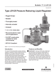
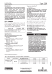
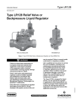
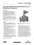
1
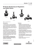
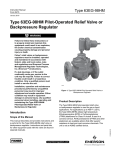
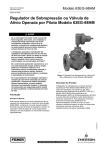
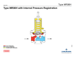
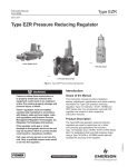
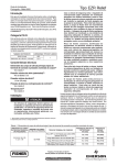
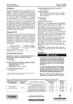
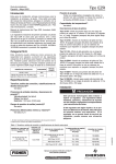
Bulletin 71.4:LR128
November 2014
Type LR128 Relief Valve or
Backpressure Liquid Regulator
•
Rugged design
•
Reliable
•
Thoroughly tested
•
Internally actuated
•
Compact
•
1, 2, 3 and 4 in. /
DN 25, 50, 80 and
100 body sizes
•
Recommended for water
and oil applications
•
Full SST construction
available for
harsh environments
•
API 614 Compliant
Figure 1. Type LR128 Relief Valve or Backpressure Regulator
Introduction
regulatorsandthespeciallyengineeredflowpath
deflectsdebris,protectingtheseatfromdamageand
erosion. The Type LR128 is used in conjunction with a
Type MR98H pilot and Type 112 restrictor. An internal
inlet strainer prevents large particles from entering the
main valve, limiting damage to internal parts.
D103577X012
The Type LR128 pilot-operated, pressure relief valve
or backpressure regulator is designed for liquid
industrial/commercial applications. The Type LR128
provides smooth operation, tight shutoff and long
life. Its internally actuated metal plug eliminates
disadvantagesassociatedwithflexibleelementstyle
www.fisherregulators.com
Bulletin 71.4:LR128
Specifications
Main Valve Body Sizes, End Connection Styles
and Structural Design Ratings(1)(2)
See Table 1
Maximum Inlet Pressure(1)
Type LR128 Main Valve: See Table 1
Type MR98H Pilot: See Table 2
Type 112 Restrictor: 1500 psig / 103 bar
Maximum Outlet Pressure
Type LR128 Main Valve: See Table 1
Type MR98H Pilot: 450 psig / 31.0 bar
Relief Set Pressure/Backpressure Control Ranges
See Table 3
Main Valve Plug Travel
1 in. / DN 25: 0.37 in. / 9.4 mm
2 in. / DN 50: 0.68 in. / 17 mm
3 in. / DN 80: 0.98 in. / 25 mm
4 in. / DN 100: 1.19 in. / 30 mm
Main Valve Minimum Differential Pressure(1)
See Table 5
Main Valve Maximum Differential Pressure(1)
See Table 6
Temperature Capabilities(1)
See Table 10
Main Valve Flow Direction
Up through the center of the cage and down
through the cage slots
Main Valve Internal Inlet Strainer Sizes
1 in. / DN 25: 12 Mesh (0.0661 in. / 1.68 mm)(3)
2, 3 and 4 in. / DN 50, 80 and 100:
10 Mesh (0.0787 in. / 2.00 mm)(3)
Flow and IEC Sizing Coefficients
Type LR128 Main Valve: See Table 7
Type MR98H Pilot: See Table 8
Type 112 Restrictor: See Table 9
Flow Capacities
See Table 13
Pressure Registration
External: 1/8 NPT
Spring Case Vent
Type Y602-12
Approximate Weights
See Table 11
Options
• Pre-piped Pilot Supply
• Travel Indicator
Construction Materials
Type LR128 Main Valve
Body: WCC Steel, CF8M or CF3M Stainless steel
Bonnet: LF2 Steel or 316/316L Stainless steel
Bonnet Bushing: 416 Hardened Stainless steel
Cage: 15-5 Stainless steel
Spring: 302 Stainless steel or 17-7 Stainless steel
Top Plug: 17-4 Stainless steel
Bottom Plug: 416 Stainless steel
Inlet Strainer: Stainless steel
Diaphragm: Nitrile (NBR) or Fluorocarbon (FKM)
O-Rings: Nitrile (NBR) or Fluorocarbon (FKM)
Flanged Locknut: 17-4 Stainless steel
Backup Rings: Polytetrafluoroethylene (PTFE)
Upper Spring Seat: 416 Stainless steel
Indicator Protector and Cover: Plastic
Indicator Stem: 303 Stainless steel
Indicator Fitting: 416 Stainless steel
Travel Indicator Plug: 416 Stainless steel
Type MR98H Pilot
Body: WCC Steel or 316 Stainless steel
Spring Case: WCC Steel or 316 Stainless steel
Orifice: 416 Stainless steel
Valve Plug: 416 Stainless Steel
Guide and Pusher Post: 416 Stainless steel
Gasket: Nitrile (NBR) or Fluorocarbon (FKM)
O-rings: Nitrile (NBR) or Fluorocarbon (FKM)
Diaphragm: Neoprene (CR) or
Fluorocarbon (FKM)
Mounting Parts
Pilot Mounting Pipe Nipple: Plated steel or
Stainless steel
Pipe Fittings: Plated steel or Stainless steel
Tubing: Stainless steel
Type 112 Restrictor
Body: 15-5 Stainless steel
Groove Valve: 416 Stainless steel
Retainer: 416 Stainless steel
Pipe Plug: 316 Stainless steel
O-rings: Nitrile (NBR) or Fluorocarbon (FKM)
1. The pressure/temperature limits in this Bulletin and any applicable standard or code limitation should not be exceeded.
2. Ratings and end connections other than ASME standards can usually be provided; contact your local Sales Office.
3. Nominal sieve opening.
2
Bulletin 71.4:LR128
7
TRIM PACKAGE
W7398
11
3
TYPE MR98H PILOT
9
TYPE MR98H PILOT
10
1
5
6
2
TYPE LR128 RELIEF VALVE OR BACKPRESSURE REGULATOR
Figure 2. Type LR128 Features and Benefits
Features and Benefits
1
2
3
Tight Shutoff – The Type LR128 uses a
diaphragm and metal plug, eliminating the
disadvantagesofflexibleelementstyleregulators.
Whenopen,themetalplugdeflectsparticlesand
debris away from the diaphragm. The result is
enhanced resistance to particle erosion, which
providesexcellentshutoffoveranextendedlife.
When closed, loading pressure and the main
spring push the diaphragm onto the taperededged seat on the cage.
Debris Protection – The specially engineered
flowpath,alongwiththemetalplug,allowsflow
through the regulator without seat impingement.
The addition of an internal inlet strainer prevents
large particles from entering the regulator,
minimizing damage to internal parts.
High Accuracy – Multiple control pressure ranges
offered by Type MR98H pilot and lower accuracy
class inherent to pilot operated pressure regulator
design provide the Type LR128 with tight and
accurate control.
4
Long Life – The robust design of the Type LR128
withitsmetalplugandspeciallyengineeredflow
pathallowsflowthroughtheregulatorwithoutseat
impingement. The diaphragm design eliminates
the possibility of taking a “set”, a common problem
withflexibleelementstyleregulators.Toprevent
damage, the diaphragm is fully supported in both
the open and closed positions. These features
enable the Type LR128 components to work
longer with less wear and tear.
5
Full Usable Capacity – Fisher® branded
regulatorsarelaboratorytested.Onehundred
percentofthepublishedflowcapacitycanbe
usedwithconfidence.
6
Thorough Laboratory Testing – Emerson
Process Management Regulator Technologies,
Inc.(Emerson™)state-of-the-artflowlaboratory
3
Bulletin 71.4:LR128
7
8
4
12
W7345
Figure 2. Type LR128 Features and Benefits (continued)
allows thorough testing of all new designs. Tests
are conducted on Fisher® branded regulators
forperformancefeaturessuchasflow,strength,
shutoff and material compatibility.
4
and shows the actual valve position. The travel
indicator makes in-service inspection and
troubleshooting easy. Also, it can be used for
remote alarming and monitoring stem position.
7
Easy In-Line Maintenance – Top-entry design
reduces maintenance time. Trim parts can
be inspected, cleaned and replaced without
removing the body from the pipeline. No
special alignment is required when replacing
the diaphragm.
10
Versatility – TheTypeLR128usestheE-body,
making available the standard construction
materialsandendconnections(ASMEandEN)
usedbyotherE-bodyregulatorsandcontrol
valves. Type MR98H can handle set pressures
up to 375 psig / 25.9 bar.
8
O-Ring Design – The Type LR128 uses
elastomerO-ringsinsteadofgaskets,reducing
maintenance and assembly time.
11
Easy-to-Maintain Pilot – The pilot is designed
to allow quick and simple in-line trim inspection
and parts replacement.
9
In-Service Travel Indicator – The optional
travel indicator responds to the precise
movement of the diaphragm and plug assembly
12
Powder Paint Coating – Carbon steel body is
powder paint coated providing superior impact,
abrasion and corrosion resistance.
Bulletin 71.4:LR128
Table 1. T
ype LR128 Main Valve Body Sizes, End Connection Styles, Structural Design Ratings and Maximum Operating
Relief (Inlet) Pressure(1)
MAIN VALVE
BODY SIZE
In.
MAIN VALVE
BODY
MATERIAL
END CONNECTION STYLE(2)
DN
WCC Steel
1, 2, 3
and 4
STRUCTURAL DESIGN
RATING(3)
25,
50, 80
and 100
CF8M
Stainless steel
maximum operating
relief (inlet)
pressure including
build-up(3)
Maximum Operating
Outlet Pressure
psig
bar
psig
bar
psig
bar
NPT or SWE
(1 and 2 in. only)
1500
103
450
31.0
450
31.0
CL150 RF
290
20.0
290
20.0
290
20.0
51.7
450
31.0
450
31.0
CL300 RF
750
CL600 RF
1500
103
PN 16/25/40 RF
580
40.0
NPT
(1 and 2 in. only)
1440
99.2
450
31.0
450
31.0
275
19.0
275
19.0
450
31.0
450
31.0
CL150 RF
275
19.0
CL300 RF
720
49.6
CL600 RF
1440
99.2
PN 16/25/40 RF
580
40.0
1. The pressure/temperature limits in this Bulletin and any applicable standard or code limitation should not be exceeded.
2. Ratings and end connections for other than ASME standard can usually be provided. Contact your local Sales Office for assistance.
3. Maximum cold working pressure (CWP) per ASME B16.34 or product bulletin limit, whichever is lowest. Temperature may decrease these maximum pressure.
Table 2. Type MR98H Pilot Maximum Cold Working Pressure(1)(2)
BODY SIZE
BODY AND SPRING
CASE MATERIAL
MAXIMUM INLET PRESSURE
MAXIMUM OUTLET PRESSURE
1/2 NPT
Steel
Stainless steel
450 psig / 31.0 bar
450 psig / 31.0 bar
1. The pressure/temperature limits in this Bulletin and any applicable standard or code limitation should not be exceeded.
2. Temperature and/or the body end connection may decrease these maximum pressure.
Table 3. Relief Set Pressure or Backpressure Control Ranges
PILOT
Type MR98H
SET PRESSURE RANGE
SPRING WIRE DIAMETER
SPRING FREE LENGTH
psig
bar
In.
mm
In.
mm
25 to 75
70 to 140
130 to 200
150 to 375(1)
1.7 to 5.2
4.8 to 9.7
9.0 to 13.8
10.3 to 25.9(1)
0.234
0.283
0.331
0.394
5.94
7.19
8.41
10.0
2.595
2.44
2.250
5.063
65.9
62.0
57.2
129
SPRING material
SPRING PART NUMBER
AND COLOR
Powder-coated steel
Powder-coated steel
Powder-coated steel
Powder-coated steel
ERAA01910A0, Green
ERAA01911A0 , Red
ERAA02889A0 , Blue
1N943427142 , Unpainted
1. 150 to 375 psig / 10.3 to 25.9 bar spring range is for the Type MR98HH pilot construction.
Pilot Type Description
Type MR98H – High-pressure relief pilot for 25 to
375 psig / 1.7 to 25.9 bar set pressure. Designed to
handle inlet pressure up to 450 psig / 31.0 bar.
A backpressure regulator is a device that maintains
a desired upstream pressure by varying the flow
in response to changes in upstream pressure. It
functions the same as a relief valve, i.e., it opens on
increasing upstream pressure.
Principle of Operation
Relief Valve
A pressure relief valve is a throttling pressure control
device that limits pressure build-up, it opens to prevent
the rise of internal pressure in excess of a specified
value. Fisher® relief valves cannot be used as ASME
safety relief valves.
As long as the inlet pressure is below the set pressure,
the Type MR98H pilot control spring keeps the pilot
valve plug closed (Figure 3). Inlet pressure passes
through the Type 112 restrictor and registers as
loading pressure on top of the Type LR128 diaphragm
5
Bulletin 71.4:LR128
TYPE 112 RESTRICTOR
TYPE MR98H PILOT
PM O C
MAIN SPRING
DIAPHRAGM AND
PLUG ASSEMBLY
internal
strainer
M1217
inlet pressure
outlet pressure
atmospheric pressure
loading pressure
Type LR128 with Type MR98H Pilot and tYPE 112 Restrictor
Figure 3. Type LR128 Operational Schematic
6
Bulletin 71.4:LR128
and plug assembly. Force from the main spring, in
addition to inlet pressure bleeding through the
Type 112 restrictor, provides a downward loading
pressure to keep the main valve diaphragm and plug
assembly tightly shutoff.
When the inlet pressure rises above the set pressure,
the pressure on the pilot diaphragm overcomes the
pilot control spring and opens the pilot valve plug. The
pilot then exhausts the loading pressure from the top
of the main valve diaphragm and plug assembly. The
inlet pressure unbalance overcomes the main spring
force and opens the diaphragm and plug assembly.
The pilot continuously exhausts process fluid when the
inlet pressure is above the set pressure.
As the inlet pressure drops below the set pressure,
the pilot control spring closes the pilot valve plug and
the exhaust to atmosphere stops. Force from the main
spring, along with pilot loading pressure, pushes the
diaphragm and plug assembly onto the tapered edge
seat, producing tight shutoff.
Backpressure Regulator
As long as inlet pressure remains below set pressure,
the Type MR98H pilot control spring keeps the pilot
valve plug closed. Force from the main spring,
in addition to inlet pressure bleeding through the
Type 112 restrictor, provides downward loading
pressure to keep the main valve diaphragm and plug
assembly tightly shutoff.
When inlet pressure rises above the set pressure,
pressure on the pilot diaphragm overcomes the control
spring to stroke the valve plug open. The pilot then
exhausts loading pressure from the top of the main
valve diaphragm. Inlet pressure unbalance overcomes
the main spring force to open the main valve
diaphragm and plug assembly.
As inlet pressure drops below set pressure, the pilot
control spring overcomes the diaphragm force to
stroke the valve plug down to close. Force from the
main spring, along with pilot loading pressure, pushes
the diaphragm and plug assembly onto the tapered
edge seat, producing tight shutoff.
Installation
The robust design of the Type LR128 allows this relief
valve or backpressure regulator to be installed indoors
or outdoors. Type LR128 is designed to withstand
the elements. The powder paint coating protects
against minor impacts, abrasions and c orrosion. When
installed outdoors, the Type LR128 does not require
protective housing. However, the Type MR98H pilot
should be oriented so that the pilot spring case vent
is pointed down. Otherwise, make sure the vent is
protected so that rain, moisture, insects or any debris
will not accumulate inside or block the vent assembly.
When installed indoors, install remote venting of the
pilot spring case as required by applicable codes
and regulations.
Cavitation Sizing
Note
The cavitation sizing graph in Figure 4 applies to water only. For cavitation
sizing for other liquids, contact your
local Sales Office.
Use Figure 4 to determine cavitation sizing of
Type L
R128. The Cavitation Prediction Curve depicts
P1 and P2 combinations where cavitation is likely
to occur. The curve shape was determined through
analysis and lab confirmation on water. Determine the
desired inlet pressure and outlet pressure of the system
and find the intersection of those values on the graph.
Continuous Service Region – Cavitation is not
expected in this region. Damage to regulator
components and piping is highly unlikely as a result
of cavitation.
Intermittent Service Region – Cavitation may
occur. Damage to regulator components and piping
is possible. This region is only suitable for intermittent
service. The risk of damage increases as P2
decreases and P1 increases or down and to the right
on the graph.
Note
Emerson™ denies responsibility for
damage and voids the warranty if
the product is used within the Full
Cavitation Region (see Figure 4).
Full Cavitation Region – Full cavitation expected.
This region is NOT recommended for service because
damage to regulator components can be expected
over time. Cavitation damage can be avoided by
dividing the total pressure drop into separate stages
that lie within the “Continuous Service Region”.
7
Bulletin 71.4:LR128
CAVITATION PREDICTION
375 /
26.0
335 /
23.1
OUTLET PRESSURE (P2)
psig / bar
295 /
20.3
255 /
17.6
215 /
14.8
175 /
12.1
135 /
9.3
95 /
6.6
55 /
3.8
15 /
1.0
0
45 /
3.1
90 /
6.2
135 /
9.3
180 /
12.4
225 /
15.5
270 /
18.6
315 /
21.7
360 /
24.8
405 /
27.9
450 /
31.0
INLET PRESSURE (P1)
psig / bar
CONTINUOUS SERVICE REGION
INTERMITTENT SERVICE REGION
FULL CAVITATION REGION
Figure 4. Cavitation Sizing for Water
Table 4. Build-up Pressure Needed to Begin Opening and Fully Open Main Valve and Pressure Drop Needed to Reseat Pilot
SPRING RANGE SPRING,
PART NUMBER AND
SPRING COLOR
25 to 75 psig / 1.7 to 5.2 bar
ERAA01910A0
(Green)
70 to 140 psig / 4.8 to 9.7 bar
ERAA01911A0
(Red)
130 to 200 psig / 9.0 to 13.8 bar
ERAA02889A0
(Blue)
150 to 375 psig / 10.3 to 25.9 bar
1N943427142
(Unpainted)
SET PRESSURE(1)
BUILDUP OVER SET
PRESSURE NEEDED TO
BEGIN OPENING OF
MAIN VALVE(2)
BUILDUP OVER SET
PRESSURE NEEDED TO
FULLY OPEN
MAIN VALVE(3)
psig
bar
psig
bar
psig
bar
psig
bar
25
1.7
1
0.07
1
0.07
2
0.14
50
3.4
1
0.07
1
0.07
2
0.14
75
5.2
1
0.07
6
0.41
2
0.14
70
4.8
1
0.07
4
0.28
5
0.34
100
6.9
1
0.07
10
0.69
5
0.34
125
8.6
1
0.07
13
0.90
5
0.34
140
9.7
1
0.07
16
1.1
5
0.34
130
9.0
1
0.07
14
0.97
6
0.41
150
10.3
1
0.07
14
0.97
6
0.41
175
12.1
1
0.07
17
1.2
6
0.41
200
13.8
1
0.07
17
1.2
6
0.41
150
10.3
1
0.07
9
0.62
7
0.48
200
13.8
1
0.07
10
0.69
7
0.48
250
17.2
1
0.07
11
0.76
7
0.48
300
20.7
1
0.07
15
1.03
7
0.48
350
24.1
1
0.07
15
1.03
7
0.48
375
25.9
1
0.07
25
1.7
7
0.48
1.Setpressureisdefinedasthepressureatwhichthepilotstarts-to-discharge.
2.Crackpointpressureofthemainvalveoftheinletpressurebuildupoverthesetpressureatwhichthemainvalvestartsaudibleflow.
3.Inletpressurebuildupoverthesetpressureforthemainvalvetoachievewide-openflowcapacity.
8
PRESSURE DROP BELOW
SET PRESSURE NEEDED
TO RESEAT PILOT
Bulletin 71.4:LR128
Table 5. Type LR128 Main Valve Minimum Differential Pressure(1)
MAIN VALVE
BODY SIZE
in.
DN
1
psid
bar d
psid
bar d
17E68 (standard)
Nitrile (NBR), Low Minimum Differential
30
2.1
30
2.1
17E97
Nitrile (NBR), High Erosion Resistance
35
2.5
35
2.5
17E88
Fluorocarbon (FKM),
High Temperature Capability
30
2.1
30
2.1
17E68 (standard)
Nitrile (NBR), Low Minimum Differential
18
1.2
19
1.3
17E97
Nitrile (NBR), High Erosion Resistance
24
1.7
24
1.7
17E88
Fluorocarbon (FKM),
High Temperature Capability
18
1.2
19
1.3
17E68 (standard)
Nitrile (NBR), Low Minimum Differential
21
1.5
28
1.9
17E97
Nitrile (NBR), High Erosion Resistance
23
1.6
23
1.6
17E88
Fluorocarbon (FKM),
High Temperature Capability
21
1.5
28
1.9
17E68 (standard)
Nitrile (NBR), Low Minimum Differential
16
1.1
30
2.1
17E97
Nitrile (NBR), High Erosion Resistance
16
1.1
34
2.3
17E88
Fluorocarbon (FKM),
High Temperature Capability
16
1.1
30
2.1
80
4
For 100% Capacity
Diaphragm Material
50
3
For 90% Capacity
Diaphragm Code
25
2
MINIMUM DIFFERENTIAL, PERCENT OF CAPACITY
Diaphragm
100
1. See Table 1 for Type LR128 main valve structural design ratings and Table 2 for Type MR98H pilot rating.
Table 6. Type LR128 Maximum Pressure Ratings and Diaphragm Selection Information(1)
Body Size
In.
maximum
Operating
inlet
pressure(3)
diaphragm
material
dn
1
25
2
50
3
80
4
100
maximum
operating
differential
pressure(3)
maximum
emergency inlet
and DifferEntial
Pressure
psig
bar
psid
bar d
psid
bar d
17E68 Nitrile (NBR), Low temperature
450
31.0
400
27.6
450
31.0
17E97 Nitrile (NBR), High-pressure
and/or erosion resistance
450
31.0
450(2)
31.0(2)
450
31.0
17E88 Fluorocarbon (FKM), High aromatic
hydrocarbon content resistance
450
31.0
450(2)
31.0(2)
450
31.0
17E68 Nitrile (NBR), Low temperature
450
31.0
400
27.6
450
31.0
17E97 Nitrile (NBR), High-pressure
and/or erosion resistance
450
31.0
450(2)
31.0(2)
450
31.0
17E88 Fluorocarbon (FKM), High aromatic
hydrocarbon content resistance
450
31.0
450(2)
31.0(2)
450
31.0
17E68 Nitrile (NBR), Low temperature
360
24.8
300
20.7
450
31.0
17E97 Nitrile (NBR), High-pressure
and/or erosion resistance
450
31.0
450(2)
31.0(2)
450
31.0
17E88 Fluorocarbon (FKM), High aromatic
hydrocarbon content resistance
450
31.0
450(2)
31.0(2)
450
31.0
17E68 Nitrile (NBR), Low temperature
360
24.8
300
20.7
450
31.0
17E97 Nitrile (NBR), High-pressure
and/or erosion resistance
450
31.0
450(2)
31.0(2)
450
31.0
17E88 Fluorocarbon (FKM), High aromatic
hydrocarbon content resistance
450
31.0
450(2)
31.0(2)
450
31.0
diaphragm
STyle
130
1. See Table 1 for main valve structural design ratings and Table 3 for pilot ratings.
2. For differential pressure above 400 psid / 27.6 bar d diaphragm temperatures are limited to 150°F / 66°C.
3. These are recommendations that provide the best regulator performance for a typical application. Please contact your local Sales Office for further information if a deviation from the
standard recommendations are required.
Table 7. Flow and Sizing Coefficients for Type LR128 Main Valve at 100% Capacity
main valve body size
Regulating
Coefficients
Wide-Open
Coefficients
Km
IEC Sizing Coefficients
in.
dn
Cv
C1
Cv
C1
XT
FD
FL
1
25
14.8
33.4
15.2
33.5
0.88
0.706
0.06
0.94
2
50
50.8
37.2
52.4
37.2
0.92
0.875
0.09
0.96
3
80
91.4
38.8
94.1
38.8
0.94
0.952
0.09
0.97
4
100
147
38.7
151
38.7
0.85
0.947
0.09
0.92
9
Bulletin 71.4:LR128
Table 8. Flow and Sizing Coefficients for Type MR98H Pilot
WIDE-OPEN COEFFICIENT
BODY SIZE
1/2 in. / DN 15
Cv
Cg
3.4
120
C1
Km
35.3
0.88
IEC SIZING COEFFICIENTS
XT
FD
FL
0.787
0.78
0.94
Km = FL2
Table 9. Type 112 Restrictor Flow Coefficients
Restrictor Setting
Cv
Setting 2
0.03
Setting 4
0.07
Setting 6
0.14
Setting 8
0.17
C1
35
Table 10. Diaphragm Material Selection Information
criteria
17E68 NITRILE (NBR)
(STANDARD)
17E97 NITRILE (NBR)
17E88 FLUOROcarbon (FKM)
Liquid Temperature
-20 to 150°F / -29 to 66°C
0 to 150°F / -18 to 66°C
0 to 250°F / -18 to 121°C(1)
General Applications
Best for low pressure differential
and cold temperature
service applications.
Best for abrasive or
erosive service applications.
Best for high
temperature applications.
Heavy Particle Erosion
Fair
Excellent
Good
1. Fluorocarbon (FKM) is limited to 200°F / 93°C in hot water.
Table 11. Approximate Weights Including Type MR98H Pilot and Restrictor
BODY SIZE
MAIN VALVE BODY, lbs / kg
in.
DN
NPT or SWE
CL150 RF
CL300 RF
CL600 RF
1
25
22 / 10
24 / 11
28 / 13
32 / 15
2
50
51 / 23
54 / 24
58 / 26
65 /29
3
80
103 / 47
107 / 49
110 / 50
123 / 56
4
100
139 / 63
145 / 66
159 / 72
192 / 87
Capacity Information
Note
Flow capacities are laboratory
verified; therefore, regulators may
be sized for 100% flow published
capacities. It is not necessary to reduce
published capacities.
The capacity information on the following pages is
based on percentages of pressure build-up over set
pressure (10%, 20%, 30% or 40%).
10
Table 12 shows Cv values at different percentages of
pressure build-up over set pressure and selected
set pressures.
Table 13 shows the liquid flow capacities of the
Type LR128 relief valve or backpressure regulator
at different percentages of pressure build-up over
set pressure and selected set pressure. Flows are in
gallons per minute (GPM) and liters per minute (L/min)
of water.
Bulletin 71.4:LR128
Table 12. Cv(1) at % Offset (Pressure Build-Up Above Setpoint)(2)
Spring Range,
Part Number
and Spring
Color
35 to 75 psig /
2.4 to 5.2 bar
1D7455T0012
(Green)
70 to 140 psig /
4.8 to 9.7 bar
1E395727192
(Red)
130 to 200 psig /
9.0 to 13.8 bar
1L380027142
(Blue)
100 to 375 psig /
6.9 to 26.0 bar
14B9942X022
(Unpainted)
BODY SIZE
Set
Pressure
1 in. / DN 25
2 in. / DN 50
3 in. / DN 80
4 in. / DN 100
psig
bar
10%
20%
30%
40%
10%
20%
30%
40%
10%
20%
30%
40%
10%
20%
30%
40%
35
2.4
14.8
14.8
14.8
14.8
50.8
50.8
50.8
50.8
91.4
91.4
91.4
91.4
147
147
147
147
50
3.4
14.8
14.8
14.8
14.8
50.8
50.8
50.8
50.8
91.4
91.4
91.4
91.4
147
147
147
147
75
5.2
14.8
14.8
14.8
14.8
50.8
50.8
50.8
50.8
91.4
91.4
91.4
91.4
147
147
147
147
70
4.8
14.8
14.8
14.8
14.8
50.8
50.8
50.8
50.8
91.4
91.4
91.4
91.4
147
147
147
147
100
6.9
14.8
14.8
14.8
14.8
50.8
50.8
50.8
50.8
91.4
91.4
91.4
91.4
147
147
147
147
125
8.6
12.5
14.8
14.8
14.8
43.0
50.8
50.8
50.8
77.4
91.4
91.4
91.4
124
147
147
147
140
9.7
13.3
14.8
14.8
14.8
51.7
50.8
50.8
50.8
87.7
91.4
91.4
91.4
141
147
147
147
130
9.0
12.0
14.8
14.8
14.8
51.9
50.8
50.8
50.8
83.7
91.4
91.4
91.4
135
147
147
147
150
10.3
14.8
14.8
14.8
14.8
50.8
50.8
50.8
50.8
91.4
91.4
91.4
91.4
147
147
147
147
175
12.1
14.8
14.8
14.8
14.8
50.8
50.8
50.8
50.8
91.4
91.4
91.4
91.4
147
147
147
147
200
13.8
14.8
14.8
14.8
14.8
50.8
50.8
50.8
50.8
91.4
91.4
91.4
91.4
147
147
147
147
100
6.9
14.8
14.8
14.8
14.8
50.8
50.8
50.8
50.8
91.4
91.4
91.4
91.4
147
147
147
147
150
10.3
14.8
14.8
14.8
14.8
50.8
50.8
50.8
50.8
91.4
91.4
91.4
91.4
147
147
147
147
200
13.8
14.8
14.8
14.8
14.8
50.8
50.8
50.8
50.8
91.4
91.4
91.4
91.4
147
147
147
147
250
17.2
14.8
14.8
14.8
14.8
50.8
50.8
50.8
50.8
91.4
91.4
91.4
91.4
147
147
147
147
300
20.7
14.8
14.8
14.8
14.8
50.8
50.8
50.8
50.8
91.4
91.4
91.4
91.4
147
147
147
147
350
24.1
14.8
14.8
14.8
14.8
50.8
50.8
50.8
50.8
91.4
91.4
91.4
91.4
147
147
147
147
375
25.9
14.8
14.8
14.8
14.8
50.8
50.8
50.8
50.8
91.4
91.4
91.4
91.4
147
147
147
147
1. Type LR128 on liquid service with 1/2 NPT Type MR98H Pilot, 100% Cage Capacity with Strainer and Type 112 Restrictor Setting of “6” for the 1 and 2 in. / DN 25 and 50 body sizes,
“6” or “8” for the 3 in. / DN 80 body size and “8” for the 4 in. / DN 100 body size.
2. Values published in this table are laboratory tested and are presented based on % offset (positive control deviation only) or pressure build-up above setpoint.
11
Bulletin 71.4:LR128
Table 13. Capacity(1), Water (GPM / L/min) for 1 and 2 in. / DN 25 and 50 Bodies at % Offset (Pressure Build-Up Above Setpoint)(2)
Spring Range,
spring Part
Number and
Spring Color
70 to 140 psig /
4.8 to 9.7 bar
1E395727192
(Red)
130 to 200 psig /
9.0 to 13.8 bar
1L380027142
(Blue)
100 to 375 psig /
6.9 to 26.0 bar
14B9942X022
(Unpainted)
1 in. / DN 25
10%
psig
35 to 75 psig /
2.4 to 5.2 bar
1D7455T0012
(Green)
BODY SIZE
Set
Pressure
20%
2 in. / DN 50
30%
40%
10%
20%
30%
40%
bar
GPM
L/min
GPM
L/min
GPM
L/min
GPM
L/min
GPM
L/min
GPM
L/min
GPM
L/min
GPM
L/min
35
2.4
92
348
81
307
84
318
88
333
266
1007
278
1052
290
1098
301
1139
50
3.4
110
416
115
435
119
450
124
469
377
1427
393
1488
410
1552
425
1609
75
5.2
134
507
140
530
146
553
152
575
461
1745
482
1824
502
1900
521
1972
70
4.8
130
492
136
515
141
534
147
556
446
1688
466
1764
485
1834
503
1904
100
6.9
155
587
162
613
169
640
175
662
533
2017
556
2104
579
2192
601
2275
125
8.6
147
556
181
685
189
715
196
742
504
1908
622
2354
648
2453
672
2544
140
9.7
165
625
192
727
200
757
207
783
642
2430
658
2491
685
2593
711
2691
130
9.0
143
541
185
700
192
727
200
757
621
2350
634
2400
660
2498
685
2593
150
10.3
190
719
199
753
207
783
214
810
653
2472
682
2581
709
2684
736
2786
175
12.1
205
776
214
810
223
844
232
878
705
2668
736
2786
766
2899
795
3009
200
13.8
220
833
229
867
239
905
248
937
753
2850
787
2979
819
3100
850
3217
100
6.9
155
587
162
613
169
640
175
662
533
2017
556
2104
579
2192
601
2275
150
10.3
190
720
199
753
207
783
214
810
653
2472
682
2581
709
2684
736
2786
200
13.8
220
833
229
867
239
905
248
939
753
2850
787
2979
819
3100
850
321
250
17.2
245
927
256
969
267
1011
277
1048
842
3187
880
3331
916
3467
950
3596
300
20.7
269
1018
281
1064
292
1105
303
1147
923
3494
964
3649
1003
3796
1041
3940
350
24.1
290
1098
303
1147
316
1196
328
1241
997
3774
1041
3940
1084
4103
1125
4258
375
25.9
301
1139
314
1188
327
1238
339
1283
1032
3906
1078
4080
1122
4247
1164
4406
1. Type LR128 on liquid service with 1/2 NPT Type MR98H Pilot, 100% Cage Capacity with Strainer and Type 112 Restrictor Setting of “6” for the 1 and 2 in. / DN 25 and 50 body sizes.
2. Values published in this table are laboratory tested and are presented based on % offset (positive control deviation only) or pressure build-up above setpoint.
12
Bulletin 71.4:LR128
Table 13. Capacity(1), Water (GPM / L/min) for 3 and 4 in. / DN 80 and 100 Bodies at % Offset (Pressure Build-Up
Above Setpoint)(2) (continued)
Spring Range,
Spring Part
Number and
Spring Color
70 to 140 psig /
4.8 to 9.7 bar
1E395727192
(Red)
130 to 200 psig /
9.0 to 13.8 bar
1L380027142
(Blue)
100 to 375 psig /
6.9 to 26.0 bar
14B9942X022
(Unpainted)
3 in. / DN 80
10%
psig
35 to 75 psig /
2.4 to 5.2 bar
1D7455T0012
(Green)
BODY SIZE
Set
Pressure
20%
4 in. / DN 100
30%
40%
10%
20%
30%
40%
bar
GPM
L/min
GPM
L/min
GPM
L/min GPM L/min GPM
L/min
GPM
L/min
GPM
L/min
GPM
L/min
35
2.4
479
1813
501
1896
521
1972
541
2048
771
2918
805
3047
838
3172
870
3293
50
3.4
678
2566
708
2680
737
2790
765
2895
1090
4126
1139
4311
1185
4485
1230
4656
75
5.2
830
3142
867
3282
903
3418
937
3547
1335
5053
1395
5280
1452
5496
1506
5700
70
4.8
802
3036
838
3172
872
3301
905
3425
1290
4883
1347
5098
1402
5307
1455
5507
100
6.9
959
3630
1001
3789
1042
3944
1081
4092
1542
5836
1610
6094
1676
6344
1739
6582
125
8.6
907
3433
1119
4235
1165
4410
1209
4576
1459
5522
1800
6813
1874
7093
1945
7362
140
9.7
1088
4118
1185
4485
1233
4667
1280
4845
1750
6624
1905
7210
1983
7506
2058
7790
130
9.0
1001
3789
1142
4322
1188
4497
1233
4667
1610
6094
1836
6949
1911
7233
1983
7506
150
10.3
1174
4444
1226
4640
1276
4830
1325
5015
1888
7146
1972
7464
2053
7771
2130
8062
175
12.1
1268
4799
1325
5015
1379
5220
1431
5416
2040
7721
2130
8062
2217
8391
2301
8709
200
13.8
1356
5132
1416
5360
1474
5579
1529
5787
2180
8251
2277
8618
2370
8970
2460
9311
100
6.9
959
3630
1001
3789
1042
3944
1081
4092
1542
5836
1610
6094
1676
6344
1739
6582
150
10.3
1174
4444
1226
4640
1276
4830
1325
5015
1888
7146
1972
7464
2053
7771
2130
8062
200
13.8
1356
5132
1416
5360
1474
5579
1529
5787
2180
8251
2277
8618
2370
8970
2460
9311
250
17.2
1516
5738
1583
5992
1648
6238
1710
6472
2438
9228
2546
9637
2650 10,030 2750
10,409
300
20.7
1660
6283
1734
6563
1805
6832
1873
7089
2670 10,106 2789 10,556 2903 10,988 3013
11,404
350
24.1
1793
6787
1873
7089
1950
7381
2023
7657
2884 10,916 3013 11,404 3136 11,870 3254
12,316
375
25.9
1856
7025
1939
7339
2018
7638
2094
7926
2986 11,302 3118 11,802 3246 12,286 3368
12,748
1. Type LR128 on liquid service with 1/2 NPT Type MR98H Pilot, 100% Cage Capacity with Strainer and Type 112 Restrictor Setting of “6” or “8” for the 3 in. / DN 80 body size and “8” for
the 4 in. / DN 100 body size.
2. Values published in this table are laboratory tested and are presented based on % offset (positive control deviation only) or pressure build-up above setpoint.
13
Bulletin 71.4:LR128
type MR98H Pilot
M
OPTIONAL
INDICATOR COVER
1/4 NPT VENT
travel indicator
t cover removal
clearance
TYPE 112
RESTRICTOR
1/8 NPT CONTROL
LINE connection
E
D
1/2 NPT PILOT
EXHAUST
connection
D1
1/4 NPT PILOT
SUPPLY connection
valve trim
v removal
clearance
G
A
B
ERAA03112_A
Figure 5. Type LR128 Dimensions Schematic
Table 15. Type LR128 Dimensions
Dimensions, In. / mm
body
size,
In. / DN
a
cl150 rf
CL300 RF
1 / 25
3.62 / 91.9
3.88 / 98.6 4.13 / 104.9 7.25 / 184.2
2 / 50
5.0 / 127.0
3 / 80
4 / 100
14
m
b
CL600 RF
CL150 RF
D
d1
E
G
CL300 RF
CL600 RF
7.75 / 196.9
8.25 / 209.6
7.40 /
189.0
5.40 /
137.0
11.39 /
289.3
5.3 / 133.4
5.6 / 143.0 10.00 / 254.0 10.50 / 266.7 11.25 / 286.0
9.00 /
229.0
6.89 /
175.0
5.9 / 149.3
6.3 / 158.8
6.6 / 168.3 11.75 / 298.5 12.50 / 317.5 13.25 / 336.6
13.30 /
338.0
9.33 /
236.9
6.9 / 176.3
7.3 / 184.2
7.8 / 196.9 13.88 / 352.6 14.50 / 368.3 15.50 / 393.7
T
v
Steel
SST
2.40 /
60.0
8.10 /
205.8
8.10 /
205.8
2.97 / 9.40 /
75.4 238.8
11.65 /
295.9
3.10 /
79.0
8.18 /
207.8
9.18 /
233.2
2.00 / 11.00 /
51.0 279.4
13.68 /
347.5
3.80 /
97.0
8.66 /
220.0
9.66 /
245.4
3.80 / 15.00 /
97.0 381.0
14.70 / 10.47 / 15.24 /
373.0 265.9 387.1
5.10 /
130.0
9.52 /
241.8
9.52 /
241.8
3.80 / 17.00 /
97.0 431.8
Bulletin 71.4:LR128
Ordering Information
Carefully review each specification on page 2, then
complete the Ordering Guide on this page. If a pilot
setpoint is not requested, the regulator will be factory
set at the approximate midrange. Please complete the
Specification Worksheet on page 16.
Ordering Guide
Body Size (Select One)
1 in. / DN 25***
2 in. / DN 50***
3 in. / DN 80***
4 in. / DN 100***
Body Material and End Connection Style
(Select One)
WCC Steel Body
NPT (Available in 1 in. and 2 in. bodies only)***
SWE (Available in 1 in. and 2 in. bodies only)***
CL150 RF***
CL300 RF***
CL600 RF***
PN 16/25/40 RF* _____________ specify
CF8M Stainless Steel Body
NPT (Available in 1 in. and 2 in. bodies only)***
CL150 RF***
CL300 RF***
CL600 RF***
PN 16/25/40 RF* _____________ specify
Main Valve Diaphragm Material (Select One)
17E68 Nitrile (NBR) (low minimum differential)
(standard)***
17E97 Nitrile (NBR) (high erosion resistance)***
17E88 Fluorocarbon (FKM)
(high temperature capability)*
Travel Indicator (Select One)
No (standard)***
Yes***
Inlet Body Tap (Select One)
Inlet body tap only (standard)***
Inlet body tap with pre-piped pilot supply***
Inlet/outlet body taps only***
Inlet/outlet body taps with pre-piped pilot supply
and pilot bleed***
Pilot Diaphragm Material (Select One)
Neoprene (CR) (standard)***
Fluorocarbon (FKM)**
Pilot Seat, Gasket and O-ring Material (Select One)
Nitrile (NBR) (standard)***
Fluorocarbon (FKM)***
Type MR98H Pilot Set Pressure Range (Select One)
25 to 75 psig / 1.7 to 5.2 bar, Green***
70 to 140 psig / 4.8 to 9.7 bar, Red***
130 to 200 psig / 9.0 to 13.8 bar, Blue***
150 to 375 psig(1) / 10.3 to 25.9 bar(1), Unpainted***
Main Valve Replacement Parts Kit (Optional)
Yes, send one diaphragm cartridge and O-rings
kit to match this order.
Pilot Replacement Parts Kit (Optional)
Yes, send one replacement kit to match this order.
Main Valve O-ring Material (Select One)
Nitrile (NBR) (standard)***
Fluorocarbon (FKM)**
1. 150 to 375 psig / 10.3 to 25.9 bar spring range is for the Type MR98HH pilot construction.
15
Bulletin 71.4:LR128
Ordering Guide (continued)
Specification Worksheet
Application:
Specific Use
Line Size
Fluid Type and Specific Gravity
Temperature
Upstream Regulator Specifications:
Brand of upstream regulator?
Orifice size of the upstream regulator?
Wide-open coefficient of the upstream regulator?
Maximum Inlet Pressure (P1max)
Downstream Pressure Setting(s) (P2)
Maximum Flow (Qmax)
Regulators Quick Order Guide
***
**
*
Readily Available for Shipment
Allow Additional Time for Shipment
Special Order, Constructed from Non-Stocked Parts.
Consult your local Sales Representative for Availability.
Relief Valve Specifications:
Relief Valve Setpoint
Accuracy Requirements?
Need for Extremely Fast Response?
Other Requirements:
Availability of the product being ordered is determined by the component with the
longest shipping time for the requested construction.
Industrial Regulators
Natural Gas Technologies
TESCOM
Emerson Process Management
Regulator Technologies, Inc.
Emerson Process Management
Regulator Technologies, Inc.
Emerson Process Management
Tescom Corporation
USA - Headquarters
McKinney, Texas 75070 USA
Tel: +1 800 558 5853
Outside U.S. +1 972 548 3574
USA - Headquarters
McKinney, Texas 75070 USA
Tel: +1 800 558 5853
Outside U.S. +1 972 548 3574
USA - Headquarters
Elk River, Minnesota 55330-2445, USA
Tels: +1 763 241 3238
+1 800 447 1250
Asia-Pacific
Shanghai 201206, China
Tel: +86 21 2892 9000
Asia-Pacific
Singapore 128461, Singapore
Tel: +65 6770 8337
Europe
Selmsdorf 23923, Germany
Tel: +49 38823 31 287
Europe
Bologna 40013, Italy
Tel: +39 051 419 0611
Europe
Bologna 40013, Italy
Tel: +39 051 419 0611
Chartres 28008, France
Tel: +33 2 37 33 47 00
Asia-Pacific
Shanghai 201206, China
Tel: +86 21 2892 9499
Middle East and Africa
Dubai, United Arab Emirates
Tel: +971 4811 8100
Middle East and Africa
Dubai, United Arab Emirates
Tel: +971 4811 8100
For further information visit www.emersonprocess.com/regulators
The Emerson logo is a trademark and service mark of Emerson Electric Co. All other marks are the property of their prospective owners. Fisher is a mark owned by Fisher Controls International LLC,
a business of Emerson Process Management.
The contents of this publication are presented for informational purposes only, and while every effort has been made to ensure their accuracy, they are not to be construed as warranties or
guarantees, express or implied, regarding the products or services described herein or their use or applicability. We reserve the right to modify or improve the designs or specifications of such
products at any time without notice.
Emerson Process Management Regulator Technologies, Inc. does not assume responsibility for the selection, use or maintenance of any product. Responsibility for proper selection, use and
maintenance of any Emerson Process Management Regulator Technologies, Inc. product remains solely with the purchaser.
©Emerson Process Management Regulator Technologies, Inc., 2012, 2014; All Rights Reserved