1
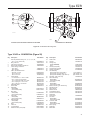
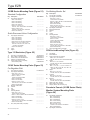
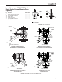
Type EZR
Instruction Manual
Form 5468
March 2014
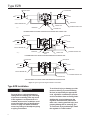
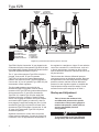
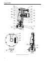
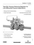
Type EZR Pressure Reducing Regulator
W7430
W8346
161AY SERIES PILOT
TYPE PRX PILOT
W7399
TYPE EZR REGULATOR
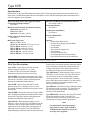
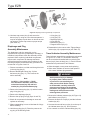
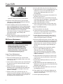
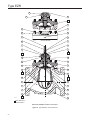
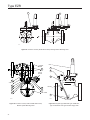
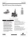
Figure 1. Type EZR Pressure Reducing Regulator
!
Introduction
WARNING
Failure to follow these instructions or
to properly install and maintain this
equipment could result in an explosion
and/or fire causing property damage and
personal injury or death.
Fisher® regulators must be installed,
operated and maintained in accordance
with federal, state and local codes, rules
and regulations and Emerson Process
Management Regulator Technologies, Inc.
(Regulator Technologies) instructions.
If the regulator vents gas or a leak
develops in the system, service to the unit
may be required. Failure to correct trouble
could result in a hazardous condition.
This instruction manual provides installation,
startup, adjustment, maintenance and parts ordering
information for Type EZR pressure reducing
regulator, Type 112 restrictor, 161AY, 161EB and
PRX Series pilot. Any accessories used with this
regulator are covered in their respective
instruction manuals.
Product Description
The Type EZR pilot-operated, pressure reducing
regulators are used for natural gas, air or other
non-corrosive gas applications and include a
Type 112 restrictor and a 161EB, 161AY or PRX Series
pilot. For applications that have high-pressure drops,
using a Type 161AYM or 161EBM monitor pilot will
increase the accuracy of the regulator.
D102600X012
Call a gas service person to service the
unit. Only a qualified person must install
or service the regulator.
Scope of the Manual
www.fisherregulators.com
Type EZR
Specifications
Specifications for the Type EZR regulator are shown below. The control spring range for the pilot is marked on the
spring case of 161EB Series pilots and on the nameplate of 161AY and PRX Series pilots. Other information for the
main valve appears on the nameplate.
Main Valve Body Sizes, End Connection Styles
and Structural Design Ratings(1)(2)
See Table 1
Maximum Inlet Pressures and Pressure Drops(1)
Main Valve: See Table 10
Pilots: See Table 3
Restrictor: 1500 psig / 103 bar
Minimum and Maximum Differential Pressures(1)
See Tables 4 and 10
Proportional Bands
See Table 2
Temperature Capabilities(1)
See Table 8
Outlet (Control) Pressure Ranges
See Table 2
Pressure Registration
External
Main Valve Plug Travel
NPS 1, 1-1/4 x 1, 2 x 1 /
DN 25, 32 x 25, 50 x 25: 0.37-inch / 9.4 mm
NPS 2 / DN 50: 0.68-inch / 17 mm
NPS 3 / DN 80: 0.98-inch / 25 mm
NPS 4 / DN 100: 1.19-inch / 30 mm
NPS 6 / DN 150: 1.5-inch / 38 mm
NPS 8 / DN 200: 1.75-inch / 44 mm
Options
• Integral Slam-Shut Device
• Pre-piped Pilot Supply and Pilot Bleed
• Travel Indicator
• Inlet Strainer
• Type 252 Pilot Supply Filter
• Trim Package
• Restricted Capacity Trim
• Pilot Diaphragm for Pressure Loading
• Quick Disconnect Union in Pilot Mounting
1. The pressure/temperature limits in this Instruction Manual and any applicable standard or code limitation should not be exceeded.
2. End connections for other than ASME standard can usually be provided, contact your local Sales Office for assistance.
Pilot Type Descriptions
Type 161AY—Low-pressure pilot with an outlet
pressure range of 6 inches w.c. to 7 psig /
15 mbar to 0.48 bar. Pilot bleeds (exhausts)
downstream through the sense (control) line.
Type 161AYM—The monitor version of the Type 161AY
pilot. The pilot bleed (exhaust) is isolated from the sense
(control) line. This pilot is used in monitoring systems
requiring an isolated pilot bleed (exhaust).
Type 161EB—High accuracy pilot with an outlet
pressure range of 5 to 350 psig / 0.34 to 24.1 bar.
Pilot bleeds (exhausts) downstream through the sense
(control) line.
Type 161EBM—The monitor version of the Type 161EB
pilot. The pilot bleed (exhaust) is isolated from the sense
(control) line. This pilot is used in monitoring systems
requiring an isolated pilot bleed (exhaust).
Type PRX/120—Outlet pressure range of 14.5 to
435 psig / 1.00 to 30.0 bar. The Type PRX/120 can be
used as the pilot on single-stage pressure reducing
regulators or as the monitor pilot or working pilot in
wide-open monitor systems. The Type PRX has a
double diaphragm which provides increased accuracy
2
and sensitivity, an integral restrictor adjustment which
allows adjustable opening and closing speeds and
a damper adjustment which adjusts inlet pressure
variability and loading pressure oscillations.
Type PRX/120-AP—Outlet pressure range of 435 to
1000 psig / 30.0 to 69.0 bar. The Type PRX/120-AP
can be used as the pilot on single-stage pressure
reducing regulators, as the monitor pilot or working
pilot in wide-open monitor systems or as the working
pilot for monitoring and working regulators in the
working monitoring systems.
Type PRX/125—Identical to the Type PRX/120 except
the restriction screw is removed. The Type PRX/125
can only be used as the monitor override pilot on
working monitor applications.
Type PRX/125-AP—Identical to the Type PRX/120-AP
except the restriction screw is removed. The
Type PRX/125-AP can only be used as the monitor
override pilot on working monitor applications.
Note
For applications requiring extremely
tight control, using a Type 161AYM or
161EBM monitor pilot will increase the
accuracy of the regulator.
Type EZR
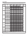
Table 1. Main Valve Body Sizes, End Connection Styles and Body Ratings
MAIN VALVE BODY SIZE, NPS / DN
MAIN VALVE BODY MATERIAL
2 x 1, 2, 3, 4 and 6 /
50 x 25, 50, 80, 100 and 150
Cast iron
1, 1-1/4 x 1 , 2 x 1, 2, 3, 4,
6 x 4(4), 8 x 4(4), 6, 8 x 6(4) and 12 x 6(4) /
25, 32 x 25, 50 x 25, 50, 80,
100,150 x 100, 200 x 100, 150,
200 x 150 and 300 x 150
WCC Steel
8 / 200
LCC Steel
END CONNECTION STYLES(1)
STRUCTURAL DESIGN
RATING(2)
NPT (NPS 2 x 1 and 2 / DN 50 x 25 and 50 only)
400 psig / 27.6 bar
CL125 FF
200 psig / 13.8 bar
CL250 RF
500 psig / 34.5 bar
NPT or SWE (NPS 1, 2 x 1 and 2 /
DN 25, 50 x 25 and 50 only)
1500 psig / 103 bar
CL150 RF
290 psig / 20.0 bar
(3)
CL300 RF
750 psig / 51.7 bar
CL600 RF or BWE
1500 psig / 103 bar
CL150 RF
290 psig / 20.0 bar
CL300 RF
750 psig / 51.7 bar
CL600 RF
1500 psig / 103 bar
1. Ratings and end connections for other than ASME standard can usually be provided. Contact your local Sales Office for assistance.
2. See Tables 3, 8, 10 and 11 for diaphragm materials and additional pressure ratings.
3. Available in steel NPT only.
4. NPS 6 x 4, 8 x 4, 8 x 6, 12 x 6 / DN 150 x 100, 200 x 100, 200 x 150, 300 x 150 Types EZR and 399 bodies are not the same as the EW valve bodies and are not interchangeable.
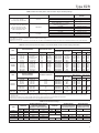
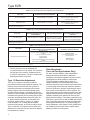
Table 2. Outlet (Control) Pressure Ranges, Proportional Bands and Pilot Control Spring Information
OUTLET (CONTROL)
PRESSURE RANGE
TYPE
psig
161AY or
161AYM
bar
6 to 15 inches w.c.
15 to 37
0.5 to 1.2
34 to 83
1.2 to 2.5
83 mbar to 0.17 bar
2.5 to 4.5
0.17 to 0.31
4.5 to 7
0.31 to 0.48
PILOT CONTROL SPRING INFORMATION
PROPORTIONAL BAND(1)(3)
Wire Diameter
Free Length
Inch
mm
Inch
mm
Olive drab
Yellow
Light green
Light blue
Black
0.105
0.114
0.156
0.187
0.218
2.67
2.90
3.96
4.75
5.54
3.75
4.31
4.13
3.94
4.13
95.2
109
105
100
105
Part Numbers
Color Code
3 mbar(2)
3 mbar(2)
34 mbar(2)
34 mbar(2)
34 mbar(2)
1B653927022
1B537027052
1B537127022
1B537227022
1B537327052
psig
bar
1-inch w.c.
1-inch w.c.
0.5
0.5
0.5
161EB or
161EBM
5 to 15
10 to 40
30 to 75
70 to 140
130 to 200
200 to 350
0.34 to 1.0
0.69 to 2.8
2.1 to 5.2
4.8 to 9.7
9.0 to 13.8
13.8 to 24.1
0.5
0.5
0.6
1.3
1.5
3
34 mbar(2)
34 mbar(2)
41 mbar(2)
90 mbar(2)
0.10(2)
0.21(2)
17B1260X012
17B1262X012
17B1259X012
17B1261X012
17B1263X012
17B1264X012
White
Yellow
Black
Green
Blue
Red
0.120
0.148
0.187
0.225
0.262
0.294
3.05
3.76
4.75
5.71
6.65
7.47
3.75
3.75
4.00
3.70
3.85
4.22
95.2
95.2
102
94.0
97.8
107
161EB(4)
30 to 300
2.1 to 20.7
6
0.41
15A9258X012
Green
0.243
6.17
1.88
47.7
OUTLET (CONTROL)
PRESSURE RANGE
TYPE
PRX/120
PRX/125
PRX/120-AP
PRX/125-AP
PILOT CONTROL SPRING INFORMATION
ACCURACY CLASS (AC)(1)
Part Numbers
Color Code
Wire Diameter
Free Length
psig
bar
Inch
mm
Inch
mm
14.5 to 26
23 to 44
41 to 80
73 to 123
1.00 to 1.8
1.6 to 3.0
2.8 to 5.5
5.0 to 8.5
2.5%
2.5%
2.5%
2.5%
M0255240X12
M0255230X12
M0255180X12
M0255220X12
Yellow
Green
Blue
Black
0.110
0.126
0.138
0.157
2.79
3.20
3.50
3.99
2.16
54.9
116 to 210
203 to 334
319 to 435
8.0 to 14.5
14.0 to 23.0
22.0 to 30.0
1%
1%
1%
M0255210X12
M0255200X12
M0255860X12
Silver
Gold
Aluminum
0.177
0.197
0.236
4.50
5.00
5.99
2.16
2.00
2.00
54.9
50.8
50.8
435 to 1000
30.0 to 69.0
1%
M0273790X12
Clear
0.335
8.51
3.93
99.8
1. Proportional band and Accuracy Class include outlet pressure drop plus hysteresis (friction), but do not include lockup.
2. P
roportional band was determined with a pressure drop ranging from 50 to 150 psig / 3.5 to 10.3 bar. Approximately double the proportional band if the pressure drop is less than
50 psig / 3.5 bar.
3. With Type 112 restrictor set on 2. With Type PRX restrictor turn the restrictor screw one turn counterclockwise from fully seated.
4. Should only be used as the intermediate reduction pilot on the Type EZR worker/monitor systems.
Table 3. Pilot Pressure Ratings
TYPE
MAXIMUM INLET
PRESSURE
MAXIMUM EMERGENCY OUTLET
PRESSURE OR MAXIMUM
EMERGENCY SENSE PRESSURE(1)
MAXIMUM OUTLET
PRESSURE
psig
bar
psig
bar
psig
bar
161AY
150
10.3
150
10.3
150
10.3
161EB
1500
103
1200
82.7
750
51.7
161AYM
150
10.3
150
10.3
161EBM
1500
103
1200
82.7
PRX Series
1480
102
1480
102
---1480
102
MAXIMUM BLEED
(EXHAUST) PRESSURE
FOR MONITOR PILOTS
psig
bar
MAXIMUM SENSE
(CONTROL) PRESSURE
FOR MONITOR PILOTS
psig
----
bar
----
150
10.3
150
10.3
1500
103
750
51.7
1480
102
1480
102
1. Maximum pressure to prevent the casings from bursting during abnormal operation (leaking to atmosphere and internal parts damage may occur).
3
Type EZR
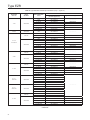
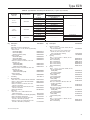
Table 4. Main Valve Minimum Differential Pressures(1)
MAIN VALVE
BODY SIZE,
NPS / DN
MAIN SPRING PART
NUMBER AND
COLOR CODE
19B2400X012, Light Blue
1 and 1-1/4 x 1 /
25 and 32 x 25
GE12727X012, Black
19B2401X012,
Black with White Stripe(3)
19B2400X012, Light Blue
2 x 1 / 50 x 25
19B2401X012,
Black with White Stripe
GE12501X012,
Red Stripe(3)
19B0951X012, Yellow
2 / 50
(2)
18B2126X012, Green
18B5955X012, Red(3)
GE05504X012, Purple(3)
T14184T0012, Yellow(2)
3 / 80
4, 6 x 4 and, 8 x 4 /
100, 150 x 100
and 200 x 100
6, 8 x 6 and
12 x 6 /
150, 200 x 150
and 300 x 150
8 / 200
19B0781X012, Light Blue
19B0782X012, Black(3)
T14184T0012, Yellow(2)
18B8501X012, Green
18B8502X012, Red(3)
19B0364X012, Yellow(2)
19B0366X012, Green
19B0365X012, Red(3)
GE09393X012, Yellow(2)
GE09396X012, Green
GE09397X012, Red(3)
DIAPHRAGM
MATERIAL
MINIMUM DIFFERENTIAL, PERCENT OF CAGE CAPACITY
FOR 90% CAPACITY
FOR 100% CAPACITY
100% Trim
60% Trim
30% Trim
100% Trim
60% Trim
30% Trim
psi bar
psi bar
psi
bar
psi bar
psi bar
psi bar
17E68 and 17E88
17E97
17E68 and 17E88
24
35
30
1.7
2.5
2.1
29
38
35
2.0
2.7
2.4
31
42
39
2.2
2.9
2.7
24
35
30
1.7
2.5
2.1
31
39
36
2.2
2.7
2.5
40
52
52
2.8
3.6
3.6
17E88 and 17E97
43
3.0
50
3.4
56
3.9
43
3.0
53
3.7
68
4.7
17E68 and 17E88
17E97
17E68 and 17E88
24
43
43
1.7
3.0
3.0
29
50
50
2.0
3.4
3.4
31
56
56
2.2
3.9
3.9
24
43
43
1.7
3.0
3.0
31
53
53
2.2
3.7
3.7
40
68
68
2.8
4.7
4.7
17E97
68
4.7
73
5.0
88
6.1
72
5.0
81
5.6
102
7.0
17E68 and 17E88
17E97
17E68 and 17E88
12
24
18
0.83
1.7
1.2
15
25
20
1.0
1.7
1.4
15
26
22
1.0
1.8
1.5
12
24
19
0.83
1.7
1.3
25
30
26
1.7
2.1
1.8
20
37
28
1.4
2.6
1.9
17E88 and 17E97
29
2.0
29
2.0
31
2.1
31
2.1
35
2.4
43
3.03
17E68, 17E88 and 17E97
17E97
17E68 and 17E88
17E88 and 17E97
17E68, 17E88 and 17E97
17E97
17E68 and 17E88
17E88 and 17E97
17E97
17E88
17E97
17E88
17E88 and 17E97
16
23
21
32
10
16
16
21
10
10
14
17
23
16
20
26
1.1
1.6
1.5
2.2
0.69
1.1
1.1
1.5
0.69
0.69
0.97
1.2
1.6
1.1
1.4
1.8
19
23
22
33
12
17
17
24
11
13
22
21
29
1.3
1.6
1.5
2.3
0.83
1.2
1.2
1.7
0.76
0.90
1.5
1.5
2.0
24
23
28
43
14
21
20
26
14
13
22
21
29
1.7
1.6
1.9
3.0
0.97
1.5
1.4
1.8
0.97
0.90
1.5
1.5
2.0
23
23
28
38
25
34
30
40
12
12
19
20
30
19
23
30
1.6
1.6
1.9
2.6
1.7
2.3
2.1
2.8
0.83
0.83
1.3
1.4
2.1
1.3
1.6
2.1
23
23
28
38
25
34
30
40
16
21
29
36
41
1.6
1.6
1.9
2.6
1.7
2.3
2.1
2.8
1.1
1.5
2.0
2.5
2.8
29
25
33
50
25
34
30
40
16
21
29
36
41
2.0
1.7
2.3
3.4
1.7
2.3
2.1
2.8
1.1
1.5
2.0
2.5
2.8
17E97
----
----
----
----
1. See Table 1 for structural design ratings, Table 3 for pilot ratings and Table 10 for maximum pressure ratings.
2. The white and yellow springs are only recommended for inlet pressures under 100 psig / 6.9 bar.
3. The red, black, purple, red stripe and black with white stripe springs are only recommended for applications where the maximum inlet pressure can exceed 500 psig / 34.5 bar.
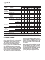
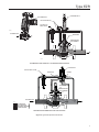
Principle of Operation
As long as the outlet (control) pressure is above the
outlet pressure setting, the pilot valve plug or disk
remains closed (Figure 2). Force from the main spring,
in addition to inlet pressure bleeding through the
Type 112 restrictor (the restrictor is integral in the
PRX Series pilots), provides downward loading
pressure to keep the main valve diaphragm and plug
assembly tightly shutoff.
When the outlet pressure decreases below the pilot
outlet pressure setting, the pilot plug or disk assembly
opens. Loading pressure bleeds downstream through
the pilot faster than it can be replaced through the
Type 112 restrictor. This reduces loading pressure on
4
top of the main valve diaphragm and plug assembly.
The force imbalance on the diaphragm allows the inlet
pressure to overcome the loading pressure and main
spring force and open the Type EZR diaphragm and
plug assembly.
As the outlet pressure rises toward the outlet pressure
setting, it compresses the pilot diaphragm against the
pilot control spring and allows the pilot valve plug or
disk close. Loading pressure begins building on the
Type EZR diaphragm and plug assembly. The loading
pressure, along with force from the main spring,
pushes the diaphragm and plug assembly onto the
tapered-edged seat, producing tight shutoff.
Type EZR
161EB SERIES PILOT
161AY SERIES PILOT
TYPE 112 RESTRICTOR
TYPE 252 PILOT
SUPPLY FILTER
B2625_2
FLOW DIRECTION
MAIN SPRING
DIAPHRAGM AND
PLUG ASSEMBLY
W7438
TYPE EZR WITH TYPES 161EB PILOT, 112 RESTRICTOR AND 252 FILTER
TYPE PRX PILOT
TYPE 252 SUPPLY FILTER
RESTRICTOR
PORT S
RU
PORT B
N 4
2
DAMPER
6
S TA
R
8
T
PORT L
PORT A
MAIN SPRING
DIAPHRAGM AND
PLUG ASSEMBLY
FLOW DIRECTION
E0790
INLET PRESSURE
OUTLET PRESSURE
ATMOSPHERIC PRESSURE
LOADING PRESSURE
TYPE EZR WITH PRX SERIES PILOT AND TYPE 252 FILTER
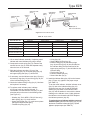
Figure 2. Type EZR Operational Schematic
5
Type EZR
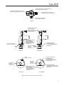
BLOCK VALVE
BLOCK VALVE
INLET
OUTLET
HAND VALVE
SUPPLY PRESSURE LINE
CONTROL LINE
ALTERNATE CONTROL LINE
RESTRICTOR
B2605_A
161 SERIES PILOT
161 SERIES SINGLE PILOT INSTALLATION WITH PILOT EXHAUST INTO CONTROL LINE
BLOCK VALVE
BLOCK VALVE
INLET
OUTLET
PILOT
EXHAUST
HAND VALVE
SUPPLY PRESSURE LINE
RESTRICTOR
B2605_B
161 SERIES
PILOT
ALTERNATE CONTROL LINE
CONTROL LINE
161 SERIES SINGLE PILOT INSTALLATION WITH SEPARATE PILOT EXHAUST LINE
BLOCK VALVE
BLOCK VALVE
INLET
OUTLET
PILOT
EXHAUST
SUPPLY PRESSURE LINE
HAND VALVE
TYPE PRX PILOT
ALTERNATE CONTROL LINE
CONTROL LINE
TYPE PRX SINGLE-PILOT INSTALLATION WITH SEPARATE PILOT EXHAUST LINE
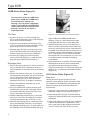
Figure 3. Typical Type EZR Single Installation Schematics
Type EZR Installation
!
WARNING
Personal injury, equipment damage or
leakage due to escaping gas or bursting
of pressure-containing parts may result
if this regulator is overpressured or is
installed where service conditions could
exceed the limits given in Specifications
section on page 2 or where conditions
exceed any ratings of the adjacent piping
or piping connections.
6
To avoid such injury or damage, provide
pressure-relieving or pressure-limiting
devices (as required by the appropriate
code, regulation or standard) to prevent
service conditions from exceeding limits.
Additionally, physical damage to the
regulator could break the pilot off the
main valve, causing personal injury and
property damage due to escaping gas.
To avoid such injury and damage, install
the regulator in a safe location.
Type EZR
All Installations
The robust design of the Type EZR allows this regulator
to be installed indoors or outdoors. When installed
outdoors, the Type EZR does not require protective
housing. This regulator is designed to withstand the
elements. The powder paint coating protects against
minor impacts, abrasions and corrosion.
When installed indoors, no remote venting is required
except on the pilot spring case. This regulator can
also be installed in a pit that is subject to flooding
by venting the pilot spring case above the maximum
possible flood level so the pilot setting can be
referenced at atmospheric pressure.
1. Only personnel qualified through training and
experience should install, operate and maintain a
regulator. Before installation, make sure that there is
no damage to or debris in the regulator. Also, make
sure that all tubing and piping are clean
and unobstructed.
Note
The Type EZR optional inlet strainer is
intended to prevent occasional large
particles from entering the main valve.
If the gas contains continuous particles,
upstream filtration is recommended.
When using an inlet strainer (key 23), do
not use the shim (key 23) and vice versa.
2. Type EZR regulator may be installed in any
orientation, as long as flow through the regulator
matches the direction of the arrow on the main
valve body. However, for easier maintenance,
install the regulator with the bonnet up.
CAUTION
When installing a Type EZR trim package
in an existing E-body, make sure flow is
up through the center of the cage and
down through the cage slots. In some
cases, correct flow path is achieved
by removing the body from the line
and turning it around. If this is done,
change the flow arrow to indicate the
correct direction. Damage may result
if flow is not in the correct direction.
After assembly, check the regulator for
shutoff and leakage to atmosphere.
300 x 150) are different than EW valve
bodies and are not interchangeable.
Install trims only in correct restricted
trim bodies.
3. The standard pilot mounting position is as shown in
Figure 1. Other mounting positions are available.
4. Apply a good grade of pipe compound to the external
pipeline threads for a threaded body or use suitable
line gaskets for a flanged body. When installing butt
weld end connections, remove trim before welding
and make sure to use approved welding practices.
Use approved piping procedures when installing
the regulator.
CAUTION
A regulator may vent some gas to the
atmosphere. In hazardous or flammable
gas service, vented gas may accumulate
and cause personal injury, death or
property damage due to fire or explosion.
Vent a regulator in hazardous gas service
to a remote, safe location away from
air intakes or any hazardous location.
Protect the vent line or stack opening
against condensation or clogging.
5. A clogged pilot spring case vent may cause the
regulator to function improperly. To prevent plugging
(and to keep the spring case from collecting moisture,
corrosive chemicals or other foreign material) point
the vent down, orient it to the lowest possible point
on the spring case or otherwise protect it. Inspect the
vent regularly to make sure it has not been plugged.
To remotely vent a spring case, remove the vent and
install obstruction-free tubing or piping into the
1/4 NPT vent tapping. Provide protection on a remote
vent by installing a screened vent cap onto the remote
end of the vent pipe. The 161AY Series pilot has a
vent restriction (key 55, Figure 20) to enhance low
flow stability. Do not remove this restriction.
!
WARNING
To avoid freeze-up because of pressure
drop and moisture in the gas, use
antifreeze practices, such as heating the
supply gas or adding a de-icing agent to
the supply gas.
Types EZR/399 restricted trim bodies
(NPS 6 x 4, 8 x 4, 8 x 6 and 12 x 6 /
DN 150 x 100, 200 x 100, 200 x 150 and
7
Type EZR
6. As shown in Figure 3, run a supply pressure line
from the upstream pipeline to the restrictor inlet
(use 3/8 NPT outer diameter tubing or larger).
Install a Type 252 pilot supply filter upstream of the restrictor, if needed, to keep the supply source
from clogging the restrictor or pilot. Inspect and
clean this filter regularly to make sure it has not
been plugged.
7. Install a downstream pressure control line (as
shown in the appropriate view of Figure 3) to the
pilot control line connection. Connect the other
end of the control line at a minimum of 8 to 10 pipe
diameters downstream of the regulator in a straight
run of pipe. Do not place a control line connection in
a turbulent area, such as in or directly downstream
of a swage or elbow. Significant restrictions in the
control line can prevent proper pressure registration.
When using a hand valve, it should be a full flow
valve, such as a full port ball valve. With a
Type 161EBM or 161AYM pilot, run a downstream
exhaust bleed line to the downstream bleed line
connection in the pilot body assembly.
8. Good piping practices usually require swaging up
to larger downstream piping to obtain reasonable
downstream fluid velocity.
Wide-Open Monitor Installations
1. Follow the procedures in the All Installations section
and then continue with step 2 of this section.
2. Pilot supply for the downstream monitoring regulator
must be obtained between the two regulators as
shown in Figure 4. With this arrangement, the
downstream monitoring regulator diaphragm
changes position with every load change. For sizing
purposes, add the minimum differential pressure
for each regulator together to establish the required
pressure drop across the station. System lock-up
pressure is equal to the setpoint of the working
regulator pilot when a Type 161EBM or a
Type 161AYM is used on an upstream regulator,
otherwise lock-up pressure is equal to monitor pilot
lock-up pressure.
Working Monitor Installations
On working monitor installations, the working monitor
regulator is always upstream and acts as a first-stage
regulator through the working pilot during normal
operation. This arrangement allows the working
monitor’s performance to be observed at all times.
Then, should the second-stage regulator fail open,
the working monitor regulator assumes the entire
pressure reduction function of the system through the
monitoring pilot.
8
Use the following procedure when installing a working
monitor system.
1. Follow the procedures in the All Installations
section and then continue with step 2 of
this section.
2. Pilot supply pressure for the downstream
Type EZR regulator must be made directly
upstream of the Type EZR using
intermediate pressure.
3. Significant restrictions in the control line can
prevent proper pressure registration. Connect the
control line a minimum of 8 to 10 pipe diameters
downstream of the regulator in a straight run of
pipe. Do not make the control line connection in a
turbulent area, such as in or directly downstream
of a swage or elbow. When used, a hand valve
should be a full flow valve such as a full port
ball valve.
4. Table 9 gives the spread between normal
distribution pressure and the minimum pressure at
which the monitor pilot can be set to take over if
the working regulator fails open.
5. Table 4 shows the minimum differential pressure
requirements across an individual regulator.
Because this application uses a first-stage
and second-stage pressure reduction, add the
minimum differential pressure for each regulator
together to establish the required pressure drop
across the station. Do not exceed maximum pilot
ratings given in Table 3.
Type EZR/PRX Working Monitor
On working monitor installations, the working monitor
regulator is always upstream and acts as a first-stage
regulator through the working pilot during normal
operation. This arrangement allows the working
monitor’s performance to be observed at all times.
Then, should the second-stage regulator fail open,
the working monitor regulator assumes the entire
pressure reduction function of the system through the
monitoring pilot. Use the following procedure when
installing a working monitor system.
As shown in Figure 5, run a supply pressure line
(use 3/8 NPT outer diameter tubing or larger) from the
upstream pipeline to the inlet (Port S) of the upstream
Type PRX-120 pilot. Install a Type 252 pilot supply
filter upstream of the pilot, if needed, to keep the
supply source from clogging the restrictor in the pilot.
Inspect and clean this filter regularly to make sure it
has not been plugged.
Connect the loading port (Port L) of the upstream
Type PRX-120 pilot to the bonnet of the upstream
Type EZR regulator. Connect the “B” port of the upstream
Type PRX-120 pilot to the “S” port of the upstream
Type EZR
BLOCK VALVE
DOWNSTREAM
REGULATOR
UPSTREAM REGULATOR
BLOCK VALVE
INLET
OUTLET
SUPPLY
PRESSURE LINE
HAND VALVE
SUPPLY
PRESSURE
LINE
RESTRICTOR
CONTROL
LINE
161 SERIES
PILOT
PILOT
RESTRICTOR
EXHAUST
161 SERIES PILOT
HAND
VALVE
B2605_C
ALTERNATE
CONTROL LINE
CONTROL LINE
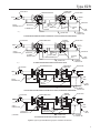
161 SERIES WIDE-OPEN MONITORING SYSTEM INSTALLATION (UPSTREAM OR DOWNSTREAM)
BLOCK VALVE
WORKING
REGULATOR
MONITOR REGULATOR
BLOCK VALVE
INLET
OUTLET
SUPPLY
PRESSURE LINE
HAND VALVE
SUPPLY
PRESSURE
LINE
RESTRICTOR
161 SERIES
MONITOR PILOT
RESTRICTOR
CONTROL LINE
161 SERIES WORKING PILOT
161 SERIES
PILOT
CONTROL LINE
B2605_D
161 SERIES WORKING MONITORING SYSTEM INSTALLATION
ALTERNATE
CONTROL LINE
DOWNSTREAM
REGULATOR
UPSTREAM REGULATOR
BLOCK VALVE
HAND
VALVE
BLOCK VALVE
OUTLET
INLET
TYPE PRX
PILOT
SUPPLY
PRESSURE LINE
SUPPLY
PRESSURE
LINE
HAND
VALVE
TYPE PRX
PILOT
PILOT
EXHAUST
HAND
VALVE
CONTROL LINE
ALTERNATE
CONTROL LINE
TYPE PRX WIDE-OPEN MONITORING SYSTEM INSTALLATION (UPSTREAM OR DOWNSTREAM)
BLOCK VALVE
WORKING
REGULATOR
MONITOR REGULATOR
OUTLET
INLET
L
SUPPLY
PRESSURE LINE
S
TYPE PRX-120
WORKING PILOT
(1) PLUGGED
BLOCK VALVE
A
B
S
A
L(1)
B
TYPE PRX-125
MONITOR PILOT
HAND
VALVE
SUPPLY
PRESSURE
LINE
CONTROL LINE
TYPE PRX WORKING MONITOR SYSTEM INSTALLATION
HAND
VALVE
ALTERNATE
CONTROL LINE
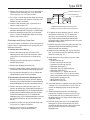
Figure 4. Typical Type EZR Monitoring System Installation Schematics
9
Type EZR
TYPE PRX/120
TYPE PRX/125
WORKING
MONITOR PILOT
PILOT
(NO RESTRICTOR SCREW)
B
S
S
A
ATMOSPHERIC PRESSURE
LOADING PRESSURE
INTERMEDIATE PRESSURE
B
A
FILTER
OUTLET
INLET
OUTLET PRESSURE
L
A
(PLUGGED)
FILTER
INLET PRESSURE
S
B
L
L
M1001
TYPE PRX/120
PILOT
INTERMEDIATE
TYPE PRX:
S- SUPPLY PORT
B- BLEED PORT
L- LOADING PORT
A - SENSING PORT
Figure 5. Type EZR-PRX-PRX Working Monitor Schematic
Type PRX-125 pilot. Connect the “A” port (located on the
underside of the pilot) of the upstream Type PRX-120 pilot
to the intermediate pressure between the first and second
Type EZR regulators as shown in Figure 5.
The “L” port of the upstream Type PRX-125 pilot is
plugged. Connect the “B” port of upstream
Type PRX-125 pilot to the intermediate pressure
between the first and second Type EZR regulators.
Connect the “A” port of upstream Type PRX-125 pilot
downstream of both regulators.
The pilot supply pressure connection for the
downstream Type EZR regulator must be directly
upstream of the Type EZR using intermediate pressure
and connected to the “S” port of the downstream
Type PRX-120. Install a Type 252 pilot supply filter
upstream of the pilot, if needed, to keep the supply
source from clogging the restrictor in the pilot. Inspect
and clean this filter regularly to make sure it has not
been plugged. Connect the loading port (Port L) of the
downstream Type PRX-120 pilot to the bonnet of the
downstream Type EZR regulator. Connect the “A” and
“B” ports of the downstream Type PRX-120 pilot to
downstream pressure.
Significant restrictions in control lines can prevent
proper pressure registration. Connect the control line
a minimum of 8 to 10 pipe diameters downstream of
10
the regulator in a straight run of pipe. Do not make the
control line connection in a turbulent area, such as in
or directly downstream of a swage or elbow. When
used, a hand valve should be a full flow valve such as
full port ball valve.
Table 4 shows the minimum differential pressure
requirements across an individual regulator. Because
this application uses a first-stage and second-stage
pressure reduction, add the minimum differential
pressure for each regulator together to establish the
required pressure drop across the station. Do not
exceed maximum pilot ratings given in Table 3.
Startup and Adjustment
Note
Table 10 shows the maximum inlet
and differential pressures for specific
constructions. Use pressure gauges to
monitor inlet pressure, outlet pressure
and any intermediate pressure
during startup.
CAUTION
To prevent damage to the Type PRX pilot
during startup, the sense and bleed lines
Type EZR
of the Type PRX should be located on the
same side of the downstream block valve.
Keep sense and bleed lines separate.
Startup for Both Single-Regulator and
Monitoring Installations
1. Make sure all block and vent valves are closed.
2. Back out the pilot adjusting screw(s).
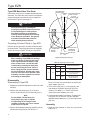
3. For easy initial startup, set the restrictor to the “8”
position. For future startups, the restrictor can be
left in the desired run position.
4. SLOWLY OPEN the valves in the following order:
a. Pilot supply and control line valve(s), if used
b. Inlet block valve
c. Outlet block valve
5. F
or a 161 Series pilot with Type 112 restrictor,
turn the restrictor(s) to position “2” or to the
desired run position. For a PRX Series pilot, turn
the restrictor screw 1 turn counterclockwise from
fully seated (turn restrictor fully clockwise then
1 turn counterclockwise) and the damper screw
fully counterclockwise.
6. F
or a single regulator, set the pilot to the desired
outlet (control) pressure according to the pilot
adjustment procedure.
F
or a wide-open downstream monitor
installation, adjust the upstream working pilot until
intermediate pressure is higher than the desired
setpoint of the monitor pilot. Adjust the downstream
monitoring pilot to the desired monitoring takeover
pressure. Reduce the upstream pilot to the normal
outlet pressure setting.
F
or a wide-open upstream monitor installation,
adjust the downstream working pilot to a setpoint
higher than the setpoint of the monitor pilot.
Adjust the upstream monitoring pilot to the desired
monitor takeover pressure. Reduce the downstream
pilot setting to normal outlet pressure setting.
F
or a working monitor installation, adjust the
setpoint of the upstream monitor pilot to the desired
maximum pressure. Adjust the upstream working
pilot to the desired intermediate pressure setting.
Adjust the downstream pilot to a pressure setting
slightly above the upstream monitor pilot pressure
setting. Adjust the upstream monitor pilot to its desired
setpoint. The setpoint of the monitor pilot should be
adjusted at least to the guidelines shown in Table 9.
The maximum may be greater. Then, establish
final desired downstream pressure by adjusting the
downstream working regulator pilot.
W4559_1
Figure 6. Restrictor Adjustment
Pilot Adjustment
For 161 Series pilots, remove the pilot closing cap
(key 16, Figure 19 or key 22, Figure 20) and, on
161EB Series only, loosen the locknut (key 12,
Figure 19). Turn the adjusting screw (key 11,
Figure 19 or key 35, Figure 20) into the spring case
(key 2, Figure 19 or key 3, Figure 20) to increase the
downstream pressure. Turn the adjusting screw out of
the spring case to decrease the downstream pressure.
For PRX Series pilots (Figure 27), loosen locknut
(key 2) and turn the adjusting screw into the spring case
to increase (or out of the spring case to decrease) the
downstream pressure. When the required downstream
pressure is maintained for several minutes, tighten the
locknut to lock the adjusting screw in position
and replace the pilot closing cap.
The Restrictor and Damper screws on the PRX Series
pilot control the regulator’s proportional band (droop)
and speed of response. Table 7 includes the appropriate
settings for low flow operation. For additional tuning
follow the steps outlined below:
1. Start with the restrictor screw 1 turn
counterclockwise from fully seated (turn restrictor
fully clockwise then 1 turn counterclockwise) and the
damper screw fully counterclockwise.
2. Turn damper screw clockwise until desired
performance is achieved. This reduces the flow path
of the damper. If the damper becomes fully seated
(no longer able to turn clockwise) and the desired
performance has not been achieved, return the
damper screw to the fully counterclockwise position.
!
WARNING
The damper screw should not be left in
the fully seated position, as it will lock
the regulator in last position which could
cause incorrect pressure regulation.
11
Type EZR
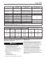
Table 5. 161 and 161EB Series Pilot Adjustment Recommendations
PILOT TYPE
RECOMMENDED TYPE 112 RESTRICTOR
SETTINGS FOR LOW FLOW OPERATION
TYPE 112 RESTRICTOR SETTINGS TO AVOID
AT LOW FLOW
161/161H Series Pilots
Restrictor Setting of “5” or greater
Avoid restrictor setting of “2” or less if continuous
flows are expected to be less than 5%
of maximum capacity
161EB Series Pilots
Restrictor Setting of “5” or greater
Avoid restrictor setting of “2” or less if continuous
flows are expected to be less than 5%
of maximum capacity
Note: Higher Type 112 restrictor settings will increase proportional band. Adjustment of the Type 112 restrictor will also cause a shift in setpoint. Setpoint should be checked and adjusted
following restrictor setting adjustment.
Table 6. Type 161AY/161AYM Pilot Adjustment Recommendations
PILOT TYPE
RECOMMENDED TYPE 112
RESTRICTOR SETTINGS FOR LOW
FLOW OPERATION
RECOMMENDED ORIFICE SIZE(S)
FOR LOW FLOW OPERATION
TYPE 112 RESTRICTOR SETTINGS
AND ORIFICE SIZES TO AVOID AT
LOW FLOW
161AY Series Pilots
Restrictor Setting of “5” or greater
3/32 or 1/8-inch / 2.38 or 3.18 mm
(3/32-inch / 2.38 mm is standard)
Avoid restrictor setting of “2” or less if
continuous flows are expected to be
less than 5% of maximum capacity
Note: Higher Type 112 restrictor settings will increase proportional band. Adjustment of the Type 112 restrictor will also cause a shift in setpoint. Setpoint should be checked and adjusted
following restrictor setting adjustment.
Table 7. Type PRX Pilot Adjustment Recommendations
PILOT TYPE
PRX/120 and PRX/120-AP Series
RECOMMENDED TYPE PRX RESTRICTOR AND DAMPER
SCREW SETTINGS FOR LOW FLOW OPERATION
TYPE PRX RESTRICTOR AND DAMPER SCREW
SETTINGS TO AVOID AT LOW FLOW
Restrictor Screw
- 1 turn out (counterclockwise) from fully seated for most
low flows
- 2-1/2 turns out (for flows less than
5% of maximum)
Restrictor Screw
- Fully seated (clockwise) or full out
(counterclockwise)
Damper Screw
- Fully out (counterclockwise) from seated for most
low flows
- One turn out (for flows less than 5% of maximum)
Damper Screw
- Full in (clockwise)
Note: Counterclockwise adjustment of the Type PRX restrictor screw will increase proportional band. Adjustment of the restrictor screw will also cause a shift in setpoint. Setpoint should
be checked and adjusted following restrictor screw adjustment.
3. Turn the restrictor screw an additional turn
counterclockwise from fully seated. This increases
the flow path of the restrictor. If additional tuning
is required, repeat step 2. Follow this method until
desired performance is achieved.
Type 112 Restrictor Adjustment
The Type 112 restrictor controls the regulator’s
proportional band (droop) and speed of response. The
restrictor can be used to fine tune the regulator for
maximum performance by decreasing the restrictor
setting for tighter control (increased opening speed,
decreased closing speed); or increasing the restrictor
setting for maximum stability (decreased opening speed,
increased closing speed). A lower setting also provides
a narrower proportional band for better accuracy. The
“8” position has the largest flow, is most stable and
easiest for startup, however, using the “8” position
is not necessary. The “0” setting has the smallest
(minimum) flow passage; at no point of rotation will the
Type 112 restrictor be completely shut off. After initial
adjustment, the restrictor does not need to be adjusted
for maintenance or startup.
12
Pilot Adjustment –
(For Low Flow Applications Only)
For stable, low flow operation, other considerations
besides pilot settings should also be addressed.
Installation of an oversized regulator may make low flow
operation difficult. When possible, a smaller-sized Type EZR should be installed. During design of a
regulator installation, the downstream piping volume
should be maximized. Control lines should not be located
in or near piping sections that may experience turbulent
flow, such as elbows or swages. Larger diameter control
lines are also recommended in low flow conditions. The
larger control lines are less restrictive and will reduce pilot
exhaust bleed backpressure to the pilot that may cause
instability. Separate sense and exhaust lines may also
help at low flow conditions. This feature is provided on the
PRX Series, Types 161M, 161HM, 161EBM and 161AYM
pilots. Control line taps should be located in straight pipe;
several pipeline diameters (8 to 10 of largest piping on
outlet) downstream of the regulator. These guidelines are
not mandatory but have been used to improve station
stability at low flow in some systems.
Type EZR
Table 8. Diaphragm Material Selection Information
17E68
NITRILE (NBR)
17E97(1)
NITRILE (NBR)
17E88
FLUOROCARBON (FKM)
Gas Temperature
(for lower temperatures
contact your local Sales Office)
-20 to 150°F / -29 to 66°C
0 to 150°F / -18 to 66°C
0 to 260°F / -18 to 127°C(2)
General Applications
Best for cold temperatures.
Best for high pressure conditions, i.e.
transmission service or high pressure
industrial service. It is also the best for
abrasive or erosive service applications.
Best for natural gas having aromatic
hydrocarbons. It is also the best for high
temperature applications.
Fair
Excellent
Good
Up to 3% aromatic hydrocarbon content(3)
Good
Excellent
3 to 15% aromatic
hydrocarbon content(3)
Poor
Good
15 to 50% aromatic
hydrocarbon content(3)
Not recommended
Poor
Good
Good
Heavy Particle Erosion
Natural Gas With:
Up to 3% H2S (hydrogen
sulfide or sour gas)
Up to 3% ketone
Up to 10% alcohol
Fair
Fair
Good
Good
Fair
Fair
Up to 3% synthetic lube
Excellent
Good
Fair
Good
1. The NPS 6 / DN 150, 17E97 diaphragm will perform in gas temperatures as low as -20°F / -29°C.
2. For differential pressures above 400 psig / 27.6 bar diaphragm temperature is limited to 150°F / 66°C.
3. The aromatic hydrocarbon content is based on percent volume.
Table 9. Type EZR Working Monitor Performance
MONITORING PILOT
Construction
Outlet (Control) Pressure Range
Spring Part Number
MINIMUM PRESSURE OVER NORMAL DISTRIBUTION
PRESSURE AT WHICH MONITOR PILOT CAN BE SET
WITH A RESTRICTOR SETTING OF 2
Type 161AY or
161AYM
6 to 15 inches w.c.
0.5 to 1.2 psig
1.2 to 2.5 psig
2.5 to 4.5 psig
4.5 to 7 psig
15 to 37 mbar
34 to 83 mbar
83 mbar to 0.17 bar
0.17 to 0.31 bar
0.31 to 0.48 bar
1B653927022
1B537027052
1B537127022
1B537227022
1B537327052
1-inch w.c.
1-inch w.c.
0.5 psig
0.5 psig
0.5 psig
2 mbar(1)
2 mbar(1)
34 mbar(1)
34 mbar(1)
34 mbar(1)
Type 161EBM
5 to 15 psig
10 to 40 psig
30 to 75 psig
70 to 140 psig
130 to 200 psig
200 to 350 psig
0.34 to 1.0 bar
0.69 to 2.8 bar
2.1 to 5.2 bar
4.8 to 9.7 bar
9.0 to 13.8 bar
13.8 to 24.1 bar
17B1260X012
17B1262X012
17B1259X012
17B1261X012
17B1263X012
17B1264X012
0.5 psig
0.5 psig
0.6 psig
1.3 psig
1.5 psig
3 psig
34 mbar(1)
34 mbar(1)
41 mbar(1)
90 mbar(1)
0.10 bar(1)
0.21 bar(1)
Type 161EB
30 to 300 psig
2.1 to 20.7 bar
15A9258X012
----
1. Monitor pilot minimum setpoint was determined with a pressure drop ranging from 50 to 150 psig / 3.5 to 10.3 bar. Approximately double the minimum monitor pilot setpoint.
Shutdown for Both Single-Regulator and
Monitoring Installations
!
WARNING
If pilot supply pressure is shut down
first, the downstream system may be
subjected to full inlet pressure.
1. If the pilot setting must be disturbed, be sure to
keep some tension on the spring. This will prevent
trapping inlet pressure during blow down.
2. Close the valves shown in Figure 3 or 4, in the
following order:
a. Inlet block valve
b. Outlet block valve
c. Control line valve(s), if used
Maintenance
Regulator parts are subject to normal wear and must
be inspected periodically and replaced as necessary.
Due to the care Regulator Technologies takes in
meeting all manufacturing requirements (heat treating,
dimensional tolerances, etc.), use only replacement
parts manufactured or furnished by Regulator
Technologies. Also, when lubrication is required,
use a good quality lubricant and sparingly coat the
recommended part. The frequency of inspection
and parts replacement depends upon the severity of
service conditions, applicable codes and government
regulations and company inspection procedures.
Table 12 lists various regulator problems and possible
solutions for them.
3. Open the vent valves to depressurize the system.
13
Type EZR
Table 10. Main Valve Maximum Pressure Ratings, Diaphragm Selection Information and Main Spring Selection(1)
BODY SIZE
NPS / DN
1 and 1-1/4 x 1 /
25 and 32 x 25
DIAPHRAGM
MATERIAL
3 / 80
4, 6 x 4
and 8 x 4 /
100, 150 x 100
and 200 x 100
6, 8 x 6
and 12 x 6 /
150, 200 x 150
and 300 x 150
8 / 200
MAXIMUM
EMERGENCY INLET
AND DIFFERENTIAL
PRESSURE
MAIN SPRING
COLOR CODE
psig
bar
psid
bar d
psid
100
6.9
100
6.9
100
6.9
Light Blue
460
31.7
400
27.6
460
31.7
Black
17E97 Nitrile (NBR)
High pressure and/or erosion
resistance
500
34.5
500
34.5
1050
72.4
Black
72.4
Black with White
Stripe(2)
Light Blue
17E68 Nitrile (NBR)
Low temperature
2 / 50
MAXIMUM
OPERATING
DIFFERENTIAL
PRESSURE(4)
17E68 Nitrile (NBR)
Low temperature
17E88 Fluorocarbon (FKM)
High aromatic hydrocarbon
content resistance
2 x 1 / 50 x 25
MAXIMUM
OPERATING INLET
PRESSURE(4)
1050
72.4
800
100
6.9
500
34.5
750
100
bar d
55.2
1050
100
6.9
100
6.9
500
34.5(3)
750
51.7
Black
51.7
500
34.5(3)
750
51.7
Black with White
Stripe(2)
6.9
100
6.9
100
6.9
Light Blue
360
24.8
300
20.7
360
24.8
Black with White
Stripe
500
34.5
500
34.5
500
34.5
Black with White
Stripe
1050
72.4
800
55.2
1050
72.4
Red Stripe(2)
17E88 Fluorocarbon (FKM)
High aromatic hydrocarbon
content resistance
100
6.9
100
6.9
100
6.9
Light Blue
750
51.7
500
34.5
51.7
Black with White
Stripe
17E68 Nitrile (NBR)
Low temperature
100
6.9
100
6.9
100
6.9
Yellow
460
31.7
400
27.6
460
31.7
Green
17E97 Nitrile (NBR)
High pressure and/or erosion
resistance
500
34.5
500
34.5
1050
72.4
Green
1050
72.4
800
55.2
1050
72.4
Red(2) or Purple(2)
Yellow
17E97 Nitrile (NBR)
High pressure and/or erosion
resistance
(3)
750
DIAPHRAGM
DESIGNATION
17E88 Fluorocarbon (FKM)
High aromatic hydrocarbon
content resistance
100
6.9
100
6.9
100
6.9
500
34.5
500
34.5(3)
750
51.7
Green
750
51.7
500
34.5(3)
750
51.7
Red(2) or Purple(2)
17E68 Nitrile (NBR)
Low temperature
100
6.9
100
6.9
100
6.9
Yellow
360
24.8
300
20.7
500
34.5
Light Blue
17E97 Nitrile (NBR)
High pressure and/or
erosion resistance
500
34.5
500
34.5
1050
72.4
Light Blue
1050
72.4
800
55.2
1050
72.4
Black(2)
17E88 Fluorocarbon (FKM)
High aromatic hydrocarbon
content resistance
100
6.9
100
6.9
100
6.9
Yellow
500
34.5
500
34.5(3)
750
51.7
Light Blue
750
51.7
500
34.5(3)
750
51.7
Black(2)
17E68 Nitrile (NBR)
Low temperature
100
6.9
100
6.9
100
6.9
Yellow
360
24.8
300
20.7
500
34.5
Green
17E97 Nitrile (NBR)
High pressure and/or
erosion resistance
100
6.9
100
6.9
100
6.9
Yellow
500
34.5
500
34.5
1050
72.4
Green
1050
72.4
800
55.2
1050
72.4
Red(2)
17E88 Fluorocarbon (FKM)
High aromatic hydrocarbon
content resistance
100
6.9
100
6.9
100
6.9
Yellow
500
34.5
500
34.5(3)
750
51.7
Green
750
51.7
500
34.5(3)
750
51.7
Red(2)
17E97 Nitrile (NBR)
High pressure and/or
erosion resistance
100
6.9
100
6.9
100
6.9
Yellow
500
34.5
500
34.5
1050
72.4
Green
1050
72.4
800
55.2
1050
72.4
Red(2)
17E88 Fluorocarbon (FKM)
High aromatic hydrocarbon
content resistance
100
6.9
100
6.9
100
6.9
Yellow
500
34.5
500
34.5(3)
750
51.7
Green
750
51.7
500
34.5(3)
750
51.7
Red(2)
17E97 Nitrile (NBR)
High pressure and/or
erosion resistance
100
6.9
100
6.9
100
6.9
Yellow
500
34.5
500
34.5
1050
72.4
Green
1050
72.4
800
55.2
1050
72.4
Red(2)
130
1. See Table 1 for main valve structural design ratings and Table 3 for pilot ratings.
2. The red, black, purple, red stripe and black with white stripe springs are only recommended for applications where the maximum inlet pressure can exceed 500 psig / 34.5 bar.
3. For differential pressures above 400 psid / 27.6 bar d diaphragm temperatures are limited to 150°F / 66°C.
4. These are recommendations that provide the best regulator performance for a typical application. Please contact your local Sales Office for further information if a deviation from the
standard recommendations is required.
14
Type EZR
LOADING CONNECTION: 1/4 NPT PIPE CONNECTS TO
TYPE EZR DIAPHRAGM LOADING PORT
PILOT SUPPLY CONNECTION: 1/4 NPT PIPE
CONNECTS TO UPSTREAM PILOT SUPPLY TAP
OUTLET CONNECTION: 1/4 NPT PIPE
CONNECTS TO PILOT INLET CONNECTION
OPTIONAL LOADING CONNECTION:
1/4 NPT NORMALLY PLUGGED
11B5004-A
TYPE 112
CONTROL LINE CONNECTION:
1/2 NPT PRESSURE
REGISTRATION ONLY. USE
3/8 NPT O.D. TUBING OR LARGER
FOR CONTROL LINE.
CONTROL LINE CONNECTION:
3/4 NPT PRESSURE
REGISTRATION AND PILOT
BLEED (EXHAUST). USE
3/4 NPT PIPE MINIMUM FOR
CONTROL LINE.
INLET 3/4 NPT CONNECTS
TO 1/4 NPT TYPE 112 OUTLET
PILOT BLEED (EXHAUST)
CONNECTION: 3/4 NPT. USE
1/2 NPT PIPE MINIMUM FOR BLEED
(EXHAUST) LINE.
INLET 3/4 NPT
CONNECTS
TO 1/4 NPT
TYPE 112 OUTLET
B2609
TYPE 161AY
TYPE 161AYM
1/4 NPT
NORMALLY PLUGGED
SENSE
OUT
INLET 1/4 NPT
CONNECTS
TO 1/4 NPT
TYPE 112 OUTLET
IN
OUT
IN
INLET 1/4 NPT
CONNECTS
TO 1/4 NPT
TYPE 112 OUTLET
CONTROL LINE CONNECTION:
1/4 NPT PRESSURE
REGISTRATION ONLY. USE
3/8 NPT O.D. TUBING OR LARGER
FOR CONTROL LINE.
PILOT BLEED (EXHAUST)
CONNECTION: 1/4 NPT. USE 3/8 NPT
O.D. TUBING OR LARGER FOR BLEED
(EXHAUST) LINE.
CONTROL LINE CONNECTION:
1/4 NPT PRESSURE
REGISTRATION AND PILOT BLEED
(EXHAUST). USE 3/8 NPT
O.D. TUBING LARGER FOR
CONTROL LINE.
21B5005-A
TYPE 161EB
TYPE 161EBM
Figure 7. Pilot Port Function and Connection Sizes
15
Type EZR
Type EZR Main Valve Trim Parts
ELASTOMER/FABRIC
MATERIAL CODE
THICKNESS
CODE
Instructions are given for complete disassembly and
assembly. The main valve may remain in the pipeline
during maintenance procedures. Key numbers are
referenced in Figures 14 through 18.
YEAR OF MANUFACTURE
RADIAL LOCATION
TO LOCATE
IMPRINT CODE
CAUTION
Avoid personal injury or damage to
property from sudden release of pressure
or uncontrolled gas or other process
fluid. Before starting to disassemble,
carefully release all pressures according
to the Shutdown procedure. Use gauges
to monitor inlet and outlet pressures
while releasing these pressures.
1 11
1
1
1
1
1
Converting a Fisher® E-Body to Type EZR
Remove all trim parts from the main valve and clean
the body interior. Then follow procedure in Assembly
section to convert a Fisher® E-body to a Type EZR.
LOCATE INK CODE
BETWEEN RADII
THICKNESS INK
CODE (USE ONE
LOCATION ONLY)
MANUFACTURER
CODE
MATERIAL
INK CODE
CAUTION
When installing a Type EZR trim package
make sure flow is up through the center
of the cage and down through the cage
slots. In some cases, correct flow path
is achieved by removing the body from
the line and turning it around. If this is
done, change the flow arrow to indicate
the correct direction. Damage may result
if flow is not in the correct direction. After
assembly, check the regulator for shutoff
and leakage to atmosphere.
DOME IDENTIFICATION
Figure 8. Diaphragm Markings
Table 11. Diaphragm Imprint Codes
STYLE
MATERIAL
Imprint Ink Mark Imprint Ink Mark
2
130
DIAPHRAGM MATERIALS
2
17E68
17E68 - Nitrile (NBR)
(low temperature)
4
17E88
17E88 - Fluorocarbon (FKM)
(high aromatic hydrocarbon
content resistance)
5
17E97
17E97 - Nitrile (NBR)
(high pressure and/or
erosion resistance)
Disassembly
Disassembly of Type EZR
1. Shutdown, isolate and depressurize the main valve
and pilot.
2. Remove the cap screws (key 3). Lift up and
remove the bonnet (key 2) from the body (key 1).
Note
For the NPS 8 / DN 200 body, the
lifting flange (key 143) is capable
of supporting the full weight of the
regulator assembly and can be utilized
to lift bonnet if required.
3. Remove the diaphragm and plug assembly (key 9)
and bonnet O-ring (key 28). For NPS 2 x 1 /
16
DN 50 x 25 sizes, use a screwdriver to remove the
upper adaptor (key 131).
4. Pull out the cage (key 7), O-ring (key 8), and
inlet strainer or strainer shim (key 23) (if no
strainer). For NPS 2 x 1 / DN 50 x 25 sizes,
remove the lower adaptor (key 132).
5. Clean parts and replace if necessary. To change the
O-ring (key 121) on a 6-inch / 152 mm cage with
attached restrictor plate (key 71), remove cap screws
(key 126).
Assembly
1. Install the inlet strainer or shim (key 23) into the
body (key 1).
Type EZR
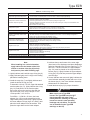
Table 12. Troubleshooting Guide
PROBLEM
POSSIBLE SOLUTION
Outlet pressure suddenly rises above
setpoint and approaches inlet pressure
• If travel indicator is in UP position, check restrictor and pilot supply filter for plugging
• If travel indicator is in DOWN position, check main valve for debris or diaphragm damage
Outlet pressure normal at low flow but
falls below setpoint at high flow
• Check main valve inlet strainer for plugging
• Check inlet pressure at high flow condition
• Check sizing calculations to be sure main valve body is large enough for load
• Check for undersized or restricted control line (use the minimum size given in step 6 of All Installations of the
Type EZR Installation section).
• Adjust restrictor to a lower setting
Outlet pressure cycles
• Adjust restrictor to a higher setting
• Check control line placement. Make sure it is not located in a turbulent area.
• Make sure there is not a restriction in the control line, such as a needle valve.
Gas escapes from pilot spring case
• Replace pilot diaphragm assembly
Gas escapes from travel indicator
• Replace indicator stem O-ring, if indicator is not desired, convert to a non-travel indicator assembly
Regulator unexpectedly closes or falls
below setpoint
• Check pilot for ice. Moisture in the gas can cause ice to form and build up in the pilot, blocking the flow.
This most commonly occurs when ambient temperature is 30 to 40°F / -1 to 4°C. Heating the regulator or
adding a de-icing agent will reduce the possibility of icing.
Outlet pressure approaches inlet
pressure when no flow is desired
• Check main valve O-rings for damage or improper installation
• Check cage and diaphragm surfaces for erosion or trapped debris
• Check pilot valve plug and seat for seating surface damage or debris
• Check pilot for ice
Regulator will not open
• Check for clogged control line
• Make sure control line is installed and open
• Check for damage to the main valve diaphragm
• On new installations, make sure the control line and pilot supply are properly connected
Regulator will not close
• Make sure the pilot supply is properly connected
• Check restrictor for clogging
• Check the main valve diaphragm for damage
• Check for a broken control line
High lock-up pressure with slow shutdown
• Check for debris on main valve or pilot seat
High lock-up pressure with fast shutdown
• Adjust restrictor to a higher setting
Note: If you were unable to solve your problem using this troubleshooting guide, contact your local Sales Office.
Note
When installing in a vertical orientation,
apply lubricant to the bottom of the inlet
strainer or strainer shim (key 23) to help
hold parts in place while installing cage.
2. Lightly lubricate and install the cage O-ring (key 8).
3. Apply lubricant lightly to all O-rings or the mating
part before installing them.
4. Install the cage (key 7) and lightly lubricate and
install the bonnet O-ring (key 28).
To assemble a 6-inch / 152 mm cage with attached
restrictor plate (key 71), lightly lubricate the O-ring
(key 121) and place it on the restrictor plate.
Secure the cage to the restrictor plate with the
cap screws (key 126), using a torque of 10 to
12 foot-pounds / 14 to 16 N•m.
F
or NPS 2 x 1 / DN 50 x 25 sizes, the lower
adaptor (key 132) must be assembled on the
cage before placing in the body. Lightly lubricate
the lower adaptor O-rings (keys 121 and 67) and
place the lower adaptor on a flat surface. Then
press the cage down into the lower adaptor.
5. Lubricate the top and bottom of the outer edge
(bead area) of the diaphragm and place diaphragm
and plug assembly (key 9) on the cage (key 7). For
NPS 2 x 1 / DN 50 x 25 sizes, the upper adaptor
(key 131) must be placed on the cage before the
bonnet (key 2). Lightly lubricate the upper adaptor
O-ring (key 133) and then press the upper adaptor
onto the cage.
6. If travel indicator was removed, lightly lubricate the
travel indicator assembly threads and screw it into
the bonnet (key 2). See Travel Indicator Assembly
Maintenance for maintenance.
7. Install the bonnet (key 2) in proper orientation.
CAUTION
Make sure to use a Type EZR
bonnet. The Type EZR bonnet is NOT
interchangeable with other Fisher®
E-body bonnets. Installing an improper
bonnet can result in stem assembly
breakage and unit failure. The bonnet
can be identified by the Type EZR
markings on the top.
17
Type EZR
DIAPHRAGM
(KEY 9)
BOTTOM PLUG
(KEY 11)
O-RING
(KEY 14)
FLANGED
LOCKNUT
(KEY 13)
O-RING
(KEY 70)
TOP PLUG
(KEY 5)
O-RING
(KEY 10)
W7394
Figure 9. Diaphragm and Plug Assembly Components
8. Lubricate cap screws (key 3) and secure the bonnet (key 2), using an even crisscross pattern. It may be necessary to push down on bonnet to start
cap screws. Tighten cap screws to proper torque
(see Table 13).
Diaphragm and Plug
Assembly Maintenance
The diaphragm and plug assembly can be
replaced as a single unit (a diaphragm cartridge) or
individual components within the assembly can be
replaced. When replacing individual components,
inspect each component for damage and wear
and replace parts as needed. Key numbers for the
following assembly and disassembly procedure are
referenced in Figures 9 and 14.
1. Place a screwdriver or similar tool through the hole
in the top plug (key 5).
2. Remove the fl anged locknut (key 13) from the bottom plug (key 11). This loosens the entire assembly.
Note
On NPS 1, 1-1/4 x 1 and 2 x 1 / DN 25,
32 x 25 and 50 x 25 bodies, remove the
socket head screw (key 129) and lock
washer (key 130) from the bottom plug.
3. Remove the bottom plug (key 11) and the bottom plug O-ring (key 10).
4. Remove the diaphragm (key 9).
• O-ring (key 14)
• O-ring (key 70)
• Diaphragm (key 9)
• O-ring (key10)
• Bottom Plug (key 11)
• Flanged Locknut (key 13)
9. Reassemble in the reverse order. Tighten fl ange locknut (key 13) to proper torque (see Table 13).
Travel Indicator Assembly Maintenance
Travel indicator assembly key numbers are referenced in Figures 10, 14 and 18. The indicator assembly
can be removed and installed without removing the
bonnet (key 2) from the body (key 1). Travel indicator maintenance is performed for two reasons:
a. When damaged or worn parts need replacing.
b. When travel indicator is removed and replaced
with a travel indicator plug assembly.
!
WARNING
Avoid personal injury or damage
to property from sudden release
of pressure or uncontrolled gas or
other process fluid. Before starting
to disassemble, carefully release all
pressures according to the shutdown
procedure. Use gauges to monitor inlet,
loading and outlet pressures while
releasing these pressures.
5. Remove the top plug O-rings (keys 14 and 70).
1. Remove the indicator protector (key 22, Figure 14) and indicator cover (key 21).
6. Check all components for damage or wear and replace as necessary.
2. Remove the fi rst hex nut (key 4) and the indicator washer (key 20). 7. When reassembling, be sure to lubricate all O-rings
before installing.
8. Hold the top plug (key 5). Place the parts on the top plug in the following order:
18
3. Unscrew the second hex nut (key 4) on the top of the indicator stem (key 15). Do not remove.
4. Use a wrench to remove indicator fi tting (key 19).
Type EZR
INDICATOR FITTING
(KEY 19)
INDICATOR COVER
(KEY 21)
W7400_1
O-RING
(KEY 18)
HEX NUTS
(KEY 4)
INDICATOR
WASHER (KEY 20)
UPPER SPRING
SEAT (KEY 17)
INDICATOR
O-RING (KEY 6)
MAIN SPRING
(KEY 12)
BACK-UP
RINGS
(KEY 16)
INDICATOR STEM
(KEY 15)
WASHER (KEY 79)
(NPS 6 / DN 150 SIZE ONLY)
Figure 10. Travel Indicator Parts
Table 13. Torque Values
BODY SIZE, NPS / DN
1 or 1-1/4 x 1 / 25 or 32 x 25
TORQUE, FOOT-POUNDS / N•m
Cap Screws
Flange Locknut
Indicator Fitting
Indicator Plug
75 to 95 / 102 to 129
4 to 6 / 5.4 to 8.1
90 to 160 / 122 to 217
90 to 160 / 122 to 217
2 x 1 or 2 / 50 x 25 or 50
55 to 70 / 75 to 95
6 to 8 / 8.1 to 11
90 to 160 / 122 to 217
90 to 160 / 122 to 217
3 / 80
100 to 130 / 136 to 176
19 to 25 / 26 to 34
200 to 300 / 271 to 407
200 to 300 / 271 to 407
4, 6 x 4 or 8 x 4 /
100, 150 x 100 or 200 x 100
160 to 210 / 217 to 285
19 to 25 / 26 to 34
200 to 300 / 271 to 407
200 to 300 / 271 to 407
6, 8 x 6 or 12 x 6 /
150, 200 x 150 or 300 x 150
275 to 300 / 373 to 407
50 to 100 / 68 to 136
300 to 425 / 407 to 577
300 to 425 / 407 to 577
8 / 200
400 to 450 / 542 to 610
90 to 110 / 122 to 149
300 to 425 / 407 to 577
300 to 425 / 407 to 577
5. Lift out travel indicator assembly. If replacing travel indicator with travel indicator plug, skip to step 9.
6. Compress the main spring (key 12). Remove the second hex nut (key 4). Parts will separate easily when the hex nut is removed.
7. Slide the indicator stem (key 15) out of the indicator fi tting (key 19). The main spring (key 12) and upper spring seat (key 17) will be free.
8. If necessary, use the indicator stem (key 15) to pry the back-up rings (key 16) and O-ring (key 18) out of the indicator fi tting (key 19).
9. Check the indicator fi tting O-ring (key 6). Lubricate and replace if necessary.
10. To replace travel indicator parts, lubricate
all O-rings, back-up rings and threads. To reassemble, hold the indicator stem (key 15) and place the parts on the stem in the following order
(see Figure 10).
• Washer (key 79 for NPS 6 / DN 150 size only)
• Main Spring (key 12), small end fi rst
• U
pper Spring Seat (key 17), make sure to place the large end toward the spring
• First Back-up Ring (key 16)
• O-ring (key 18)
• Second Back-up Ring (key 16)
• I ndicator Fitting (key 19), the back-up rings (key 16) and O-ring (key 18) should slide into the indicator fi tting and the small end of the upper spring seat (key 17) should slide into the indicator fi tting.
• First Hex Nut (key 4)
• Indicator Washer (key 20)
• Second Hex Nut (key 4)
11. Install the indicator fi tting (key 19) into the bonnet (key 2, Figure 14), tighten to the proper torque (see Table 13).
To set the travel indicator, hold the indicator cover
(key 21) next to the indicator fi tting (key 19). Screw the hex nuts (key 4) and the indicator washer (key 20) down on the indicator stem (key 15) until the washer is even with the lowest marking on the indicator cover. Lightly lubricate the indicator cover threads and install. Replace
the indicator protector (key 22).
To replace the travel indicator with the non-travel
indicator option, place the main spring (key 12) into the bonnet. Install the indicator plug (key 19) and tighten to proper torque (see Table 13).
19
Type EZR
161EB Series Pilots (Figure 19)
Note
This procedure covers all 161EB Series
pilots. Types 161EB and 161EBM rated
for outlet pressure settings over
200 psig / 13.8 bar require a diaphragm
limiter. Types 161EB and 161EBM pilots
rated for outlet pressure settings under
200 psig / 13.8 bar do not require a
diaphragm limiter.
Trim Parts
1. As shown in Figure 11, remove the body plug
(key 3) to let the plug spring (key 6) and valve plug
(key 4) drop freely from the body.
2. Inspect the removed parts and body plug O-ring
(key 15), replace as necessary and make sure the
plug seating surfaces are free from debris.
3. Sparingly apply lubricant to the body plug O-ring
(key 15) and the threads of the body plug (key 3).
Install the body plug O-ring over the body plug.
4. Stack the plug spring (key 6) and valve plug
(key 4) on the body plug (key 3). Install the body plug with stacked parts into the body (key 1).
Diaphragm Parts
1. Remove the closing cap (key 16), loosen the locknut
(key 12) and back out the adjusting screw (key 11)
until compression is removed from the control spring
(key 9).
2. Remove the machine screws (key 13, not shown)
and separate the spring case (key 2) from the body
(key 1). Remove the control spring seat (key 8),
the control spring (key 9). If used, remove the
diaphragm limiter (key 10). Replace if necessary.
3. Remove the diaphragm assembly (key 7) and
inspect the diaphragm.
4. On Type 161EBM pilots, inspect the stem guide
seal assembly (key 19) and, if damaged, replace
the complete assembly. Inspect the outer O-ring
(key 22) and replace if necessary.
5. Install the diaphragm assembly (key 7) and push
down on it to see if the valve plug (key 4) strokes
smoothly and approximately 1/16-inch / 1.6 mm.
6. Stack the control spring (key 9), control spring seat
(key 8) and diaphragm limiter (key 10) (if used) on
the diaphragm assembly (key 7). If used, make sure
the diaphragm limiter is installed beveled side up on
20
W4570-1
Figure 11. 161EB Series Pilot Trim Removal/Installation
Types 161EB and 161EBM pilots with 200 to
350 psig / 13.8 to 24.1 bar outlet pressure range.
Lightly apply lubricant to the control spring seat.
7. Install the spring case (key 2) on the body (key 1)
with the vent (key 18) properly oriented. Make sure
the vent is not directly over inlet or outlet piping due
to possible icing. Install the machine screws (key 13,
not shown), using a crisscross pattern, torque them
to 5 to 7 foot-pounds / 6.8 to 9.5 N•m for stainless
steel bodies and 2 to 3 foot-pounds / 2.7 to 4.1 N•m
for aluminum bodies. Lubricate the adjusting
screw threads.
8. When maintenance is complete, refer to the Startup
and Adjustment section to put the regulator back
into operation and adjust the pressure setting.
Tighten the locknut (key 12), replace the closing cap
gasket (key 17) if necessary and install the closing
cap (key 16).
161AY Series Pilots (Figure 20)
Body Area
Use this procedure to gain access to the disk
assembly, orifice and body O-ring. All pressure must
be released from the diaphragm casing and the disk
assembly must be open, before these steps can
be performed.
1. Remove the cap screws (key 2) and separate the
diaphragm casing (key 4) from the body (key 1).
2. Remove body seal O-ring (key 11) and the back-up
ring (key 50). Inspect the body seal O-ring and replace
if necessary.
3. Inspect and replace the orifice (key 5) if necessary. Lubricate the threads of the replacement orifice
with a good grade of light grease and install with
29 to 37 foot-pounds / 39 to 50 N•m of torque.
Type EZR
4. Remove the cotter pin (key 15) if it is necessary to replace the disk assembly (key 13) or the throat seal O-ring (key 31) of a Type 161AYM.
5. For a Type 161AYM, inspect the throat seal O-ring
(key 31) and remove the machine screw (key 33). Replace O-ring if necessary.
6. Install the disk assembly (key 13) and secure it with the cotter pin (key 15).
7. Place back-up ring (key 50) into the body (key 1) then place the body seal O-ring (key 11) into the body. 8. Place the diaphragm casing (key 4) on the body (key 1). Secure the diaphragm casing to the body with the cap screws (key 2).
Diaphragm and Spring Case Area
Use this procedure to change the control spring and to inspect, clean or replace parts in the spring case and
diaphragm assembly.
To Change the Control Spring:
1. Remove the closing cap (key 22) and turn the adjusting screw (key 35) counterclockwise until all compression is removed from the control spring
(key 6). 2. Change the control spring (key 6) to match the desired spring range.
3. Replace the adjusting screw (key 35).
4. Install the replacement closing cap gasket (key 25) if necessary and reinstall the closing cap (key 22).
5. If the spring was changed, be sure to change the
stamped spring range on the nameplate.
To Disassemble and Reassemble Diaphragm Parts
1. Remove the closing cap (key 22) and turn adjusting screw (key 35) counterclockwise to remove adjusting screw, baffl e plate (key 56) and control spring (key 6).
2. Remove the spring case hex nuts (key 23, not shown), cap screws (key 24) and spring case (key 3).
3. Remove the diaphragm (key 10) and attached parts by tilting them so that the pusher post (key 8) slips off the lever assembly (key 16). To separate the diaphragm (key 10) from the attached parts, unscrew the machine screw (key 38) from the pusher post (key 8).
4. Inspect the pusher post (key 8) and the body seal O-ring (key 11), replace if required.
5. Remove hex nut (key 21) to separate the diaphragm (key 10) and attached parts.
BODY SEAL O-RING (KEY 11)
BACK-UP RING (KEY 50)
BODY (KEY 1)
Figure 12. Expanded View of the Body Area
Showing the O-ring and Back-up Ring Placement
6. To replace the lever assembly (key 16), remove the machine screws (key 17). To replace the stem (key 14) or access the stem seal O-ring (key 30) also perform Body Area Maintenance procedure steps 1 and 4 and pull the stem out of the
diaphragm casing (key 4).
7. Install the stem (key 14) into the guide insert (key 18) and perform Body Area Maintenance procedure
steps 6 through 8 as necessary.
8. Install the lever assembly (key 16) into the stem (key 14) and secure the lever assembly with the machine screws (key 17).
9. Install the parts on the pusher post in the order
listed below:
• Pusher Post (key 8)
• Pusher Post Connector (key 40)
• Connector Seal O-ring (key 49)
• Diaphragm Head (key 7)
• Diaphragm (key 10), pattern side up
• Diaphragm Head (key 7)
• Hex Nut (key 21) — Tighten the hex nut 9 to 11 foot-pounds / 12 to 15 N•m to secure parts to the pusher post connector (key 40)
• Overpressure Spring (key 39)
• Spring Holder (key 37)
• Machine Screw (key 38)
10. Insert and tighten the machine screw (key 38) with a torque of 1 to 3 foot-pounds / 1.4 to 4.1 N•m to secure the diaphragm parts to the pusher post
(key 8).
11. Install the assembled parts in the diaphragm
casing (key 4). Make sure the lever (key 16) fi ts in the pusher post (key 8) and that the holes in the diaphragm (key 10) align with the holes in the diaphragm casing.
12. Place the spring case (key 3) on the diaphragm casing (key 4) so the vent assembly (key 26) is oriented correctly and secure with the cap screws
(key 24) and hex nuts (key 23, not shown), fi ngertight only.
21
Type EZR
6. Set the pad holder (key 22) in the body (key 16).
7. Lightly lubricate the rims of the diaphragm (key 14)
and place it on top of the pad holder (key 22).
Set the upper diaphragm plate (key 13) on
the diaphragm.
8. Lightly lubricate the O-ring (key 18) and place it in
the lower cover (key 21).
W4573
Figure 13. Pushing Groove Valve Up With Retainer
13. Insert the control spring (key 6) into the spring
case (key 3), followed by the baffle plate (key 56)
and adjusting screw (key 35).
14. Turn the adjusting screw (key 35) clockwise until
there is enough spring (key 6) force to provide proper
slack to the diaphragm (key 10). Using a crisscross
pattern, tighten the cap screws (key 24) and hex nuts
(key 23, not shown) to 14 to 17 foot-pounds /
19 to 23 N•m of torque. To adjust the outlet pressure
to the desired setting, refer to Startup and
Adjustment section.
9. Place the washer (key 11) and stem nut (key 20)
on the stem (key 23) and tighten. If also performing
Upper Case Maintenance, skip to step 2 of the
Upper Case Maintenance section.
10. Insert machine screws (key 10) in the lower cover
(key 21) and tighten uniformly to ensure proper seal.
Upper Case Maintenance
1. Remove pressure from the pilot.
2. Loosen locknut (key 2) and back out adjusting
screw (key 1) until compression is removed from
the spring (key 7). Remove cap (key 3).
15. Install a replacement closing cap gasket (key 25) if
necessary and then install the closing cap (key 22).
3. Lift the upper spring seat (key 6), spring (key 7)
and O-ring (key 4) out of the upper cover (key 8).
Inspect O-ring and replace if necessary.
PRX Series Maintenance
4. Remove machine screws (key 10) from lower cover
(key 21) and the separate lower cover from the body
(key 16), unless removed during lower diaphragm
maintenance. Use a wrench to hold stem (key 23)
securely while removing the upper diahragm nut
(key 26).
CAUTION
Always remove spring compression before
performing maintenance on this unit.
To remove spring compression, loosen
locknut (key 2, Figure 27) and back out
adjusting screw (key 1) until compression
is removed from the spring (key 7).
Lower Case Maintenance
1. Remove pressure from the pilot.
2. Remove machine screws (key 10) from lower
cover (key 21) and the separate lower cover from
the body (key 16).
3. Use a wrench to hold the stem (key 23) and loosen
the stem nut (key 20). Remove the stem nut and
washer (key 11).
4. Remove the upper diaphragm plate (key 13),
diaphragm (key 14), pad holder (key 22) and O-ring
(key 18). Inspect parts for damage or wear and
replace if necessary.
5. Remove orifice (key 19) and O-ring (key 17).
Inspect the parts for damage or wear and replace if
necessary. Lightly lubricate the O-ring and place in
the body (key 16). Install the orifice.
22
5. Remove remaining loose components: washer
(key 11), upper diaphragm plate (key 13),
diaphragm (key 14), lower diaphragm plate
(key 15) and O-rings (keys 18 and 25). Inspect
diaphragm and O-rings for damage or wear and
replace if necessary.
6. Lightly lubricate the O-ring (key 25). Place O-ring
over the stem (key 23) and press it down into the
body (key 16).
7. Set the lower diaphragm plate (key 15) into the
body (key 16).
8. Lightly lubricate the rims of the diaphragm (key 14)
and place it in the body (key 16) on top of the lower
diaphragm plate (key 15).
9. Set the upper diaphragm plate (key 13) on top of
the diaphragm (key 14).
10. Place washer (key 11) and upper diaphragm nut
(key 26) on the stem (key 23) and tighten using a
wrench to hold the stem.
11. Set the upper spring seat (key 6).
Type EZR
Damper and Restrictor Maintenance
Parts Ordering
1. Remove screw (key 31, Figure 27) and plate (key 29).
When corresponding with your local Sales Office about
this equipment, reference the equipment serial number
or FS number found on a nameplate attached to the
bonnet. When ordering replacement parts, reference
the key number of each needed part as found in
the following parts list. Separate kit containing all
recommended spare parts is available.
2. Remove ring nuts (key 30).
3. Remove damper adjusting screw (key 27).
Remove and inspect O-ring (key 28) for damage
or wear and replace if necessary. Lightly lubricate
O-ring before placing on the adjusting screw. Insert
damper adjusting screw into the body (key 16) and
tighten. Insert ring nut (key 30) and tighten. Back
out damper adjusting screw until it stops.
4. Remove restrictor adjusting screw with hole (key 32).
Remove and inspect O-ring (key 28) for damage or
wear and replace if necessary. Lightly lubricate O-ring
before placing on the adjusting screw. Insert restrictor
adjusting screw into the body (key 16) and completely
tighten. Insert ring nut (key 30) and completely
tighten. Back out restrictor adjusting screw 1/2 turn.
Note
When using a Type PRX/120 pilot with a
Type PRX/125 pilot as a monitor, use the
following settings:
• Restrictor - completely tighten and
then back out three full turns.
• Damper - back out until it stops.
5. Install plate (key 29) and screw (key 31).
Type 112 Restrictor
Perform this procedure only if O-rings are leaking.
Key numbers are referenced in Figure 22.
1. Unscrew the groove valve (key 22) and retainer
(key 23) just enough to loosen them, but do not
completely separate.
2. As shown in Figure 14, push on the retainer
(key 23) to push the groove valve (key 22) out of
the body (key 21), then complete disassembly.
3. Replace the groove valve O-rings (key 24) if
necessary, being sure to lightly apply lubricant to
the replacement O-rings before installing them in
the groove valve and retainer.
4. Install the groove valve (key 22) into the same
side of the body where the scale appears. Install
the retainer into the opposite side of the body and
tighten until both are secure.
5. When all maintenance is complete, refer to the
Startup and Adjustment section to put the regulator
back into operation.
Parts List
Type EZR Main Valve (Figures 14 to 18)
Note
On an NPS 1-1/4 x 1, 2 x 1, 6 x 4, 8 x 4, 8 x 6
or 12 x 6 / DN 32 x 25, 50 x 25, 150 x 100,
200 x 100, 200 x 150 or 300 x 150 body, the
first digit indicates the end connection size
and the second digit indicates the trim size.
Order parts according to trim size unless
otherwise indicated.
Key Description Part Number
Parts Kits
Diaphragm Cartridge and O-rings (Included are keys 5,
6, 8, 9, 10, 11, 13, 14, 16, 18, 28, 66, 67, 70 and 121)
NPS 1 and 1-1/4 x 1 / DN 25 and 32 x 25
17E68 Nitrile (NBR)
10C0502X032
17E97 Nitrile (NBR)
REZRX00CS12
17E88 Fluorocarbon (FKM)
10C0502X052
NPS 2 x 1 / DN 50 x 25
17E68 Nitrile (NBR)
10C0502X042
17E97 Nitrile (NBR)
REZRX00CS92
17E88 Fluorocarbon (FKM)
10C0502X022
NPS 2 / DN 50
17E68 Nitrile (NBR)
18B5959X012
17E97 Nitrile (NBR)
18B5959X022
17E88 Fluorocarbon (FKM)
18B5959X062
NPS 3 / DN 80
17E68 Nitrile (NBR)
18B9884X022
17E97 Nitrile (NBR)
18B9884X032
17E88 Fluorocarbon (FKM)
18B9884X072
NPS 4, 6 x 4, 8 x 4 / DN 100, 150 x 100, 200 x 100
17E68 Nitrile (NBR)
18B8508X022
17E97 Nitrile (NBR)
18B8508X032
17E88 Fluorocarbon (FKM)
18B8508X072
NPS 6, 8 x 6, 12 x 6 / DN 150, 200 x 150, 300 x 150
17E97 Nitrile (NBR)
REZRX00CS62
17E88 Fluorocarbon (FKM)
19B2840X042
NPS 8 / DN 200
17E97 Nitrile (NBR)
REZRX00CS82
Diaphragm and O-rings (Included are
keys 6, 8, 9, 10, 13, 14, 18, 28 and 70)
NPS 1 / DN 25
17E68 Nitrile (NBR)
19B2412X022
17E97 Nitrile (NBR)
REZRX000S12
17E88 Fluorocarbon (FKM)
19B2412X072
NPS 2 x 1 / DN 50 x 25
17E68 Nitrile (NBR)
19B2412X062
17E97 Nitrile (NBR)
REZRX000S92
17E88 Fluorocarbon (FKM)
19B2412X052
23
Type EZR
Table 14. Type EZR Main Valve Body Part Numbers (key 1, Figure 14)
BODY SIZE,
NPS / DN
1 / 25
1-1/4 x 1 /
32 x 25
BODY
MATERIAL
GE11581X012
GE11440X012
CL150 RF
GE11583X012
14B5623X032
CL300 RF
GE11607X012
14B5623X042
CL600 RF
GE11608X012
14B5623X052
SCH 40 BWE
GE11610X012
14B5623X122
SCH 80 BWE
GE11611X012
WCC Steel
NPT
GE11582X012
NPT
GE10583X012
Cast iron
CL125 FF
GE10585X012
14B5834X012
CL250 RF
GE10587X012
14B5834X022
NPT
GE10588X012
SWE
GE10682X012
CL150 RF
GE10676X012
14B5834X032
CL300 RF
GE10678X012
14B5834X042
CL600 RF
GE10679X012
14B5834X052
SCH 40 BWE
GE10680X012
14B5834X072
SCH 80 BWE
GE10681X012
WCC Steel
Cast iron
3 / 80
WCC Steel
Cast iron
4 / 100
WCC Steel
WCC Steel
WCC Steel
Cast iron
6 / 150
WCC Steel
-----------
-----------
-----------
CL125 FF
GE10689X012
CL250 RF
GE10698X012
CL150 RF
GE10699X012
14B5835X032
CL300 RF
GE10700X012
14B5835X042
CL600 RF
GE10701X012
14B5835X052
SCH 40 BWE
GE10702X012
14B5835X102
SCH 80 BWE
GE10703X012
-----------
CL125 FF
GE10707X012
CL250 RF
GE10822X012
CL150 RF
GE10835X012
14B5836X032
CL300 RF
GE10839X012
14B5836X042
CL600 RF
GE10842X012
14B5836X052
SCH 40 BWE
GE10843X012
14B5836X092
SCH 80 BWE
GE10844X012
CL150 RF
GE11772X012
CL300 RF
GE16359X012
CL600 RF
GE17626X012
SCH 40 BWE
GE16448X012
SCH 80 BWE
GE16561X012
CL150 RF
GE17629X012
CL300 RF
GE17630X012
-----------
-----------
CL600 RF
GE17631X012
SCH 40 BWE
GE17627X012
SCH 80 BWE
GE17628X012
CL125 FF
GE11444X012
CL250 RF
GE11445X012
CL150 RF
GE11447X012
24B5837X032
CL300 RF
GE11449X012
24B5837X042
CL600 RF
GE11451X012
24B5837X052
SCH 40 BWE
GE11452X012
24B5837X072
SCH 80 BWE
GE11453X012
-----------
- continued -
24
Tapped Inlet and Tapped Outlet
NPT
WCC Steel
8x4/
200 x 100
BODY STYLE
Standard
(Included Tapped Inlet)
SWE
2 x 1, 2 /
50 x 25, 50
6x4/
150 x 100
END CONNECTION
STYLE
Type EZR
Table 14. Type EZR Main Valve Body Part Numbers (key 1, Figure 14) (continued)
BODY SIZE,
NPS / DN
8x6/
200 x 150
12 x 6 /
300 x 150
BODY MATERIAL
END CONNECTION
STYLE
BODY STYLE
Standard
(Included Tapped Inlet)
CL150 RF
GE19084X012
CL300 RF
GE19089X012
CL600 RF
GE19090X012
SCH 40 BWE
GE19091X012
SCH 80 BWE
GE19092X012
CL150 RF
GE19095X012
CL300 RF
GE19096X012
CL600 RF
GE19097X012
SCH 40 BWE
GE19093X012
SCH 80 BWE
GE19094X012
WCC Steel
WCC Steel
CL150 RF
8 / 200
CL300 RF
LCC Steel
CL600 RF
Parts Kits
Diaphragm and O-rings (Included are
keys 6, 8, 9, 10, 13, 14, 18, 28 and 70) (continued)
NPS 2 / DN 50
17E68 Nitrile (NBR)
17E97 Nitrile (NBR)
17E88 Fluorocarbon (FKM)
NPS 3 / DN 80
17E68 Nitrile (NBR)
17E97 Nitrile (NBR)
17E88 Fluorocarbon (FKM)
NPS 4, 6 x 4 and 8 x 4 / DN 100, 150 x 100
and 200 x 100
17E68 Nitrile (NBR)
17E97 Nitrile (NBR)
17E88 Fluorocarbon (FKM)
NPS 6, 8 x 6 and 12 x 6 / DN 150, 200 x 150
and 300 x 150
17E97 Nitrile (NBR)
17E88 Fluorocarbon (FKM)
NPS 8 / DN 200
17E97 Nitrile (NBR)
1
Valve Body
2
Bonnet Assembly
NPS 1 and 1-1/4 x 1 / DN 25 and 32 x 25 bodies
NPS 2 x 1 and 2 / DN 50 x 25 and 50 bodies
NPS 3 / DN 80 body NPS 4, 6 x 4 and 8 x 4 / DN 100, 150 x 100
and 200 x 100 bodies
NPS 6, 8 x 6 and 12 x 6 / DN 150, 200 x 150
and 300 x 150 bodies
NPS 8 / DN 200 body
3 Cap Screw
NPS 1 and 1-1/4 x 1 / DN 25 and 32 x 25
bodies (4 required) NPS 2 x 1 or 2 / DN 50 x 25 or 50 body (8 required)
NPS 3 / DN 80 body (8 required)
NPS 4, 6 x 4 and 8 x 4 / DN 100, 150 x 100
and 200 x 100 bodies (8 required)
NPS 6, 8 x 6 and 12 x 6 / DN 150, 200 x 150
and 300 x 150 bodies (12 required)
Part Number
18B5952X012
18B5952X022
18B5952X062
18B9885X022
18B9885X032
18B9885X072
18B8507X022
18B8507X032
18B8507X072
REZRX000S62
19B2837X042
REZRX000S82
See Table 14
39B2403X022
38B2122X022
38B5963X022
38B2133X022
49B0355X022
GE18697X022
1R281124052
1A453324052
1A454124052
1A440224052
1U513124052
-----------
FA144718X12
-----------
SCH 40 BWE
Key Description Tapped Inlet and Tapped Outlet
FA144717X12
FA144716X12
49B5961X022
Key Description Part Number
4
Hex Nut (2 required)
NPS 1, 1-1/4 x 1, 2 x 1 and 2 / DN 25, 32 x 25
50 x 25 and 50 body
1H322228982
NPS 3, 4, 6 x 4, 8 x 4, 6, 8 x 6 and 12 x 6 /
DN 80, 100, 150 x 100, 200 x 100, 150,
200 x 150 and 300 x 150 body
1L286338992
NPS 8 / DN 200 body
1A573528982
5
Top Plug
NPS 1, 1-1/4 x 1 and 2 x 1 / DN 25, 32 x 25
and 50 x 25 bodies 29B2404X012
NPS 2 / DN 50 body 28B2130X012
NPS 3 / DN 80 body 28B8511X012
NPS 4 / DN 100 body 28B5964X012
NPS 6 / DN 150 body
39B0370X012
NPS 8 / DN 200 body
39B5071X012
6* O-ring
NPS 1, 1-1/4 x 1, 2 x 1 and 2 / DN 25, 32 x 25,
50 x 25 and 50 bodies
Nitrile (NBR)
18B3438X012
Fluorocarbon (FKM)
1N430306382
NPS 2 / DN 50 body
Nitrile (NBR)
18B3438X012
Fluorocarbon (FKM)
1N430306382
NPS 3 / DN 80 body
Nitrile (NBR)
10A8931X012
Fluorocarbon (FKM)
10A8931X052
NPS 4, 6 x 4 and 8 x 4 / DN 100, 150 x 100
and 200 x 100 bodies
Nitrile (NBR)
10A8931X012
Fluorocarbon (FKM)
10A8931X052
NPS 6, 8 x 6 and 12 x 6 / DN 150, 200 x 150
and 300 x 150 bodies
Nitrile (NBR)
10A3800X012
Fluorocarbon (FKM)
1R727606382
NPS 8 / DN 200 body
Nitrile (NBR)
10A3800X012
Fluorocarbon (FKM)
1R727606382
7
Cage
NPS 1, 1-1/4 x 1 and 2 x 1 / DN 25, 32 x 25
and 50 x 25 bodies 39B2413X012
NPS 2 / DN 50 body
37B9748X012
*Recommended Spare Part
25
Type EZR
Key Description 7
Cage (continued)
NPS 3 / DN 80 body NPS 4 / DN 100 body
NPS 6 x 4 / DN 150 x 100 body
NPS 8 x 4 / DN 200 x 100 body
NPS 6, 8 x 6 and 12 x 6 / DN 150, 200 x 150
and 300 x 150 bodies
NPS 8 / DN 200 body
8* Cage O-ring (not required for NPS 2 x 1 or 8 x 6 /
DN 50 x 25 or 200 x 150) bodies
NPS 1 / DN 25 body
Nitrile (NBR)
Fluorocarbon (FKM)
NPS 2 / DN 50 body
Nitrile (NBR)
Fluorocarbon (FKM)
NPS 3 / DN 80 body
Nitrile (NBR)
Fluorocarbon (FKM)
NPS 4, 6 x 4 and 8 x 4 / DN 100, 150 x 100
and 200 x 100 bodies
Nitrile (NBR)
Fluorocarbon (FKM)
NPS 6, 8 x 6 and 12 x 6 / DN 150, 200 x 150
and 300 x 150 bodies
Nitrile (NBR)
Fluorocarbon (FKM)
NPS 8 / DN 200 body
Nitrile (NBR)
Fluorocarbon (FKM)
9*Diaphragm
NPS 1, 1-1/4 x 1 and 2 x 1 / DN 25, 32 x 25
and 50 x 25 bodies
17E97 Nitrile (NBR), high pressure
17E88 Fluorocarbon (FKM)
17E68 Nitrile (NBR), low pressure
NPS 2 / DN 50 body
17E68 Nitrile (NBR), low temperature
17E97 Nitrile (NBR), high pressure
17E88 Fluorocarbon (FKM)
NPS 3 / DN 80 body
17E68 Nitrile (NBR), low temperature
17E97 Nitrile (NBR), high pressure
17E88 Fluorocarbon (FKM)
NPS 4, 6 x 4 and 8 x 4 / DN 100, 150 x 100
and 200 x 100 bodies
17E68 Nitrile (NBR), low temperature
17E97 Nitrile (NBR), high pressure
17E88 Fluorocarbon (FKM)
NPS 6, 8 x 6 and 12 x 6 / DN 150, 200 x 150
and 300 x 150 bodies
17E97 Nitrile (NBR)
17E88 Fluorocarbon (FKM)
NPS 8 / DN 200 body
17E97 Nitrile (NBR)
10*O-ring
NPS 1, 1-1/4 x 1, 2 x 1 and 2 / DN 25, 32 x 25,
50 x 25 and 50 bodies
Nitrile (NBR)
Fluorocarbon (FKM)
NPS 2 / DN 50 body
Nitrile (NBR)
Fluorocarbon (FKM)
NPS 3, 4, 6 x 4 and 8 x 4 / DN 80, 100,
150 x 100 and 200 x 100 bodies
Nitrile (NBR)
Fluorocarbon (FKM)
NPS 6, 8 x 6 and 12 x 6 / DN 150, 200 x 150
and 300 x 150 bodies
Nitrile (NBR)
Fluorocarbon (FKM)
*Recommended Spare Part
26
Part Number
48B5961X012
48B2135X012
29B1881X012
29B1883X012
49B0353X012
59B5955X012
14A5713X012
13A2351X012
10B4428X012
10B4428X022
10B4366X012
10B4366X022
10B4373X012
10B4373X022
1H862306992
1H8623X0022
1V9229X0042
1V9229X0022
GE11960X012
39B2397X022
30C1009X012
29B1909X012
28B2123X052
29B2715X012
38B9886X012
39B2726X012
38B8512X022
38B8509X012
39B3996X012
39B1154X012
49B0357X012
40C1035X012
40C1888X012
1E216306992
1L949306382
1E216306992
1L949306382
1J4888X0052
1J4888X0032
11A8741X052
11A8741X012
Key Description 10* O-ring (continued)
NPS 8 / DN 200 body
Nitrile (NBR)
Fluorocarbon (FKM)
11 Bottom Plug
NPS 1, 1-1/4 x 1 and 2 x 1 / DN 25, 32 x 25
and 50 x 25 bodies
NPS 2 / DN 50 body
NPS 3 / DN 80 body
NPS 4, 6 x 4 and 8 x 4 / DN 100, 150 x 100
and 200 x 100 bodies
NPS 6, 8 x 6 and 12 x 6 / DN 150, 200 x 150
and 300 x 150 bodies
NPS 8 / DN 200 body
12 Main Spring
NPS 1, 1-1/4 x 1 and 2 x 1 / DN 25, 32 x 25
and 50 x 25 bodies
White
Black
Red Stripe (NPS 2 x 1 / DN 50 x 25 body only)
Light Blue
Black with White Stripe
NPS 2 / DN 50 body
Yellow
Green
Red for use with travel indicator
Purple for use with non-travel indicator
NPS 3 / DN 80 body
Yellow
Light Blue
Black
NPS 4, 6 x 4 and 8 x 4 / DN 100, 150 x 100
and 200 x 100 bodies
Yellow
Green
Red
NPS 6, 8 x 6 and 12 x 6 / DN 150, 200 x 150
and 300 x 150 bodies
Yellow
Green
Red
NPS 8 / DN 200 body
Yellow
Green
Red
13 Flanged Locknut NPS 2 / DN 50 body
NPS 3, 4, 6 x 4 and 8 x 4 / DN 80, 100,
150 x 100 and 200 x 100 bodies
NPS 6, 8 x 6, 12 x 6 / DN 150,
200 x 150 and 300 x 150 bodies
NPS 8 / DN 200 body
14* Top Plug O-ring
NPS 1, 1-1/4 x 1 and 2 x 1 / DN 25, 32 x 25
and 50 x 25 bodies
Nitrile (NBR)
Fluorocarbon (FKM)
NPS 2 / DN 50 body
Nitrile (NBR)
Fluorocarbon (FKM)
NPS 3, 4, 6 x 4 and 8 x 4 / DN 80, 100,
150 x 100 and 200 x 100 bodies
Nitrile (NBR)
Fluorocarbon (FKM)
NPS 6, 8 x 6 and 12 x 6 / DN 150, 200 x 150
and 300 x 150 bodies
Nitrile (NBR)
Fluorocarbon (FKM)
NPS 8 / DN 200 body
Nitrile (NBR)
Fluorocarbon (FKM)
Part Number
1F4636X0032
1N571406382
19B2407X012
18B2127X012
18B8513X012
18B5966X012
29B0763X012
29B5958X012
19B2399X012
GE12727X012
GE12501X012
19B2400X012
19B2401X012
19B0951X012
18B2126X012
18B5955X012
GE05504X012
T14184T0012
19B0781X012
19B0782X012
T14184T0012
18B8501X012
18B8502X012
19B0364X012
19B0366X012
19B0365X012
GE09393X012
GE09396X012
GE09397X012
18B2139X012
15A7591X012
19B0361X012
10C1267X012
13A1584X052
13A1584X022
13A1584X052
13A1584X022
10A3803X062
10A3803X032
T12050X0012
T12050X0022
T12050X0012
T12050X0022
Type EZR
21
22
20
15
19
4
17
6
2
18
14
16
70
64
12
10
48B2142
B2617_2
28
11
9
5
13
7
1
8
23
MAIN VALVE ASSEMBLY FOR NPS 1, 1-1/4 x 1, 2 x 1, 2, 3, 4, 6 x 4 AND 8 x 4 / DN 25, 32 x 25, 50 x 25, 50, 80, 100, 150 x 100 AND 200 x 100 BODY SIZES
(NOTE: SEE NPS 2 x 1 / DN 50 X 25 ASSEMBLY FOR ADDITIONAL PARTS)
Figure 14. Type EZR Main Valve
Key Description 15 Stem
NPS 1, 1-1/4 x 1 and 2 x 1 /
DN 25, 32 x 25 and 50 x 25 bodies
NPS 2 / DN 50 body with travel indicator
NPS 3 and 4 / DN 80 and 100 bodies
NPS 6 / DN 150 body
NPS 8 / DN 200 body
16 Back-up Ring (2 required)
NPS 1, 1-1/4 x 1, 2 x 1 and 2 /
DN 25, 32 x 25, 50 x 25 and 50 bodies
NPS 3, 4, 6 x 4, 8 x 4, 6, 8 x 6 and 12 x 6 /
DN 80, 100, 150 x 100, 200 x 100, 150,
200 x 150 and 300 x 150 bodies
NPS 8 / DN 200 body
17 Upper Spring Seat
NPS 1, 1-1/4 x 1 and 2 x 1 /
DN 25, 32 x 25 and 50 x 25 bodies
NPS 2 / DN 50 body with travel Indicator
NPS 3, 4, 6 x 4 and 8 x 4 /
DN 80, 100, 150 x 100 and 200 x 100 bodies
NPS 6, 8 x 6 and 12 x 6 /
DN 150, 200 x 150 and 300 x 150 bodies
NPS 8 / DN 200 body
Part Number
T14185T0012
T14185T0012
T21074T0012
29B0366X012
29B5076X012
1N659106242
1J418806992
1K786806992
18B2129X012
18B2129X012
18B5968X012
29B0764X012
20C1357X012
Key Description Part Number
18* O-ring
NPS 1, 1-1/4 x 1, 2 x 1 and 2 / DN 25, 32 x 25,
50 x 25 and 50 bodies
Nitrile (NBR)
1H2926X0032
Fluorocarbon (FKM)
1H2926X0022
NPS 3, 4, 6 x 4, 8 x 4, 6, 8 x 6 and 12 x 6 / DN 80,
100, 150 x 100, 200 x 100, 150, 200 x 150
and 300 x 150 bodies
Nitrile (NBR)
1D191706992
Fluorocarbon (FKM)
1N423906382
NPS 8 / DN 200 body
Nitrile (NBR)
1E472706992
Fluorocarbon (FKM)
1N430406382
19 Indicator Fitting
NPS 1, 1-1/4 x 1, 2 x 1 and 2 / DN 25, 32 x 25,
50 x 25 and 50 bodies
28B2128X012
NPS 3, 4, 6 x 4 and 8 x 4 / DN 80, 100,
150 x 100 and 200 x 100 bodies
28B5969X012
NPS 6, 8 x 6, 12 x 6 / DN 150, 200 x 150
and 300 x 150 bodies
39B0358X012
NPS 8 / DN 200 body
30C1356X012
*Recommended Spare Part
27
Type EZR
Key Description 19
Indicator Plug
NPS 1, 1-1/4 x 1 and 2 x 1 / DN 25, 32 x 25
and 50 x 25 bodies
NPS 2 / DN 50 body
NPS 3, 4, 6 x 4 and 8 x 4 / DN 80, 100,
150 x 100 and 200 x 100 bodies
NPS 6, 8, 8 x 6 and 12 x 6 / DN 150, 200,
200 x 150 and 300 x 150 bodies
20
Indicator Washer
NPS 1, 1-1/4 x 1, 2 x 1 and 2 / DN 25, 32 x 25,
50 x 25 and 50 bodies
NPS 3, 4, 6 x 4, 8 x 4, 6, 8 x 6 and 12 x 6 / DN 80,
100, 150 x 100, 200 x 100, 150, 200 x 150
and 300 x 150 bodies
NPS 8 / DN 200 body
21 Indicator Cover
NPS 1, 1-1/4 x 1, 2 x 1 and 2 / DN 25, 32 x 25,
50 x 25 and 50 bodies
NPS 3, 4, 6 x 4 and 8 x 4 / DN 80, 100,
150 x 100 and 200 x 100 bodies
NPS 6, 8, 8 x 6 and 12 x 6 / DN 150, 200,
200 x 150 and 300 x 150 bodies
22 Indicator Protector
NPS 1, 1-1/4 x 1, 2 x 1 and 2 / DN 25, 32 x 25,
50 x 25 and 50 bodies
NPS 3, 4, 6 x 4, 8 x 4, 6, 8, 8 x 6 and 12 x 6 / DN 80,
100, 150 x 100, 200 x 100, 150, 200, 200 x 150
and 300 x 150 bodies
23 Inlet Strainer
NPS 1 and 1-1/4 x 1 / DN 25 and 32 x 25 bodies
NPS 2 x 1 and 2 / DN 50 x 25 and 50 bodies
NPS 3 / DN 80 body
NPS 4 / DN 100 body
NPS 6 / DN 150 body
NPS 8 / DN 200 body
23 Strainer Replacement Shim
NPS 1 and 1-1/4 x 1 / DN 25 and 32 x 25 bodies
NPS 2 x 1 and 2 / DN 50 x 25 and 50 bodies
NPS 3 / DN 80 body
NPS 4 / DN 100 body
NPS 6 / DN 150 body
NPS 8 / DN 200 body
24 Nameplate
25 Flow Arrow
NPS 1 to 1-1/4 x 1 / DN 25 to 32 x 25 bodies
NPS 2 x 1, 2, 3, 4, 6 and 8 / DN 50 x 25, 50,
80, 100, 150 and 200 bodies
26 Drive Screw
For NPS 1 and 1-1/4 x 1 / DN 25
and 32 x 25 (4 required)
For NPS 2 x 1, 2, 3, 4 and 6 / DN 50 x 25, 50,
80, 100 and 150 (5 required)
For NPS 8 / DN 200 (6 required)
28* O-ring
NPS 1 and 1-1/4 x 1 / DN 25 and 32 x 25 bodies
Nitrile (NBR)
Fluorocarbon (FKM)
NPS 2 x 1 and 2 / DN 50 x 25 and 50 bodies
Nitrile (NBR)
Fluorocarbon (FKM)
NPS 3 / DN 80 body
Nitrile (NBR)
Fluorocarbon (FKM)
NPS 4 / DN 100 body
Nitrile (NBR)
Fluorocarbon (FKM)
NPS 6 / DN 150 body
Nitrile (NBR)
Fluorocarbon (FKM)
*Recommended Spare Part
28
Part Number
19B2409X012
GE17585X012
28B5970X012
39B0767X012
18B2138X012
18B8503X012
20C2461X012
T14188T0012
19B2270X012
19B4691X012
24B1301X012
29B2269X012
20B8004X012
10B4409X012
20B4367X012
20B4374X012
20B7853X012
29B5966X012
13B8061X012
13B8062X012
13B8063X012
13B8064X012
13B8065X012
39B5967X012
----------1V105938982
1V106038982
1A368228982
19B2838X012
19B2838X022
18B2124X012
18B2124X022
18B8514X012
18B8514X022
18B2140X012
18B2140X022
19B0359X012
10A3591X012
Key Description 28* O-ring (continued)
NPS 8 / DN 200 body
Nitrile (NBR)
Fluorocarbon (FKM)
47
Hex Nut, SA194-2H
(NPS 8 / DN 200 body only) (8 required)
63
Pilot Supply Pipe Plug (2 required)
64
Bonnet Pipe Plug
For NPS 2, 3, 4 and 8 / DN 50, 80, 100 and 200 For NPS 6 / DN 150
66
O-ring (NPS 8 x 6 / DN 200 x 150 body only)
Nitrile (NBR)
Fluorocarbon (FKM)
67O-ring
NPS 2 x 1 / DN 50 x 25 body
Nitrile (NBR)
Fluorocarbon (FKM)
NPS 8 x 6 / DN 200 x 150 body
Nitrile (NBR)
Fluorocarbon (FKM)
70*O-ring
NPS 1, 1-1/4 x 1 and 2 x 1 / DN 25, 32 x 25
and 50 x 25 bodies
Nitrile (NBR)
Fluorocarbon (FKM)
NPS 2 / DN 50 body
Nitrile (NBR)
Fluorocarbon (FKM)
NPS 3 and 4 / DN 80 and 100 bodies
Nitrile (NBR)
Fluorocarbon (FKM)
NPS 6 / DN 150 body
Nitrile (NBR)
Fluorocarbon (FKM)
NPS 8 / DN 200 body
Nitrile (NBR)
Fluorocarbon (FKM)
71
Restrictor Plate
NPS 1, 1-1/4 x 1 and 2 x 1 / DN 25, 32 x 25
and 50 x 25 bodies
For 60% Capacity Trim
For 30% Capacity Trim
NPS 2 / DN 50 body
For 60% Capacity Trim
For 30% Capacity Trim
NPS 3 / DN 80 body
For 60% Capacity Trim
For 30% Capacity Trim
NPS 4, 6 x 4 and 8 x 4 / DN 100, 150 x 100
and 200 x 100 bodies
For 60% Capacity Trim
For 30% Capacity Trim
NPS 6 / DN 150 body
For 100% Capacity Trim
For 60% Capacity Trim
For 30% Capacity Trim
NPS 8 x 6 / DN 200 x 150 body
For 100% Capacity Trim
For 60% Capacity Trim
For 30% Capacity Trim
NPS 12 x 6 / DN 300 x 150 body
For 100% Capacity Trim
For 60% Capacity Trim
For 30% Capacity Trim
72 E-Ring, for Restricted Trim
NPS 1, 1-1/4 x 1 and 2 x 1 / DN 25, 32 x 25
and 50 x 25 bodies
NPS 2 / DN 50 body
NPS 3 / DN 80 body
NPS 4 / DN 100 body
Part Number
1P5585X0022
1P5585X0032
1A4452X0612
1A767524662
1A767524662
1A369224492
18A2556X022
18A2556X032
10B4428X012
10B4428X022
1V335006562
1V3350X0012
13A1584X052
13A1584X022
13A1584X052
13A1584X022
10A3803X062
10A3803X032 T12050X0012
T12050X0022
T12050X0012
T12050X0022
19B2835X012
19B2836X012
18B2144X012
18B2145X012
28B8516X012
28B8517X012
28B8504X012
28B8505X012
49B0367X012
49B0368X012
49B0369X012
49B0768X012
49B0776X012
49B0775X012
49B0769X012
49B2396X012
49B0777X012
19B2411X012
16A7882X012
18B8518X012
18B8506X012
6
Type EZR
TOP PLUG (KEY 5)
O-RING (KEY 14)
O-RING (KEY 70)
DIAPHRAGM (KEY 9)
BOTTOM PLUG (KEY 11)
O-RING (KEY 10)
LOCK WASHER (KEY 130)
SOCKET HEAD SCREW (KEY 129)
19B2408
NPS 1, 1-1/4 x 1 AND 2 x 1 / DN 25, 32 x 25 AND 50 x 25
DIAPHRAGM ASSEMBLY
22
21
21
20
20
22
19
15
17
17
2
2
14
14
70
64
11
12
10
28
11
10
5
7
4
6
4
19
70
15
18
6
16
18
5
79
7
121
71
126
12
28
79
9
121
13
9
131
13
121
8
126
8
1
67
23
1
71
133
64
16
132
23
MAIN VALVE ASSEMBLY FOR NPS 6, 8 x 6 AND 12 x 6 /
DN 150, 200 x 150 AND 300 x 150 BODY SIZES
49B5067
NPS 2 x 1 / DN 50 x 25 MAIN VALVE ASSEMBLY
121
126
66
66
66
67
67
67
NPS 8 x 6 / DN 200 x 150 RESTRICTOR PLATE O-RING PLACEMENT
Figure 14. Type EZR Main Valve (continued)
29
Type EZR
144
143
19
L
136
24
47
26
25
21
4
22
20
2
19
16
6
L
L
18
64
17
12
142
15
28
137
L
40C3570-C
70
14
L
9
10
11
13
7
5
8
1
L
23
APPLY LUBRICANT (L)
PARTS NOT SHOWN: 63
MAIN VALVE ASSEMBLY FOR NPS 8 / DN 200 BODY
Figure 14. Type EZR Main Valve (continued)
30
Type EZR
3
24
25
26
B2617_A2
Figure 15. Type EZR Nameplate and Flow Arrow
8
72
71
23
B2617_D
B2617_C
Figure 16. Type EZR Restricted Trim
Figure 17. Type EZR Cage O-ring Placement
19
19
3
3
B2617_E
NPS 1, 1-1/4 x 1, 2 x 1, 2, 3 AND 4 /
DN 25, 32 x 25, 50 x 25, 50, 80 AND 100 BODY SIZES
NPS 6 x 4, 8 x 4, 6, 8 x 6, 12 x 6 /
DN 150 x 100, 200 x 100, 150, 200 x 150, 300 x 150 BODY SIZES
Figure 18. Type EZR Travel Indicator Plug Option
31
Type EZR
11
12
16
16
11
17
8
17
12
L
9
L
8
2
2
38
9
10
38
18
7
18
7
19
L
1
1
L
22
15
4
15
L
4
3
6
6
3
37B1199
37B1193
APPLY LUBRICANT (L)
TYPE 161EB PILOT
TYPE 161EBM PILOT
19
22
SENSE
(CONTROL)
PORT
19
1
22
SENSE
(EXHAUST)
PORT
31B5012-A
TYPE 161EBM PILOT
Figure 19. 161EB Series Pilots
32
Type EZR
Table 15. 161EB Series Pilot Part Numbers (keys 7, 8, 9, 10 and 11, Figure 19)
OUTLET (CONTROL) PRESSURE RANGE AND SPRING COLOR CODE
KEY
PART
NAME
Type 161EB or 161EBM
Type 161EB(3)
5 to 15 psig /
0.34 to 1.0 bar
White
10 to 40 psig /
0.69 to 2.8 bar
Yellow
30 to 75 psig /
2.1 to 5.2 bar
Black
70 to 140 psig /
4.8 to 9.7 bar
Green
130 to 200 psig /
9.0 to 13.8 bar
Blue
200 to 350 psig /
13.8 to 24.1 bar
Red
30 to 300 psig /
2.1 to 20.7 bar
Green
Diaphragm Assembly,
Nitrile (NBR)
17B9055X022(1)
17B9055X022(1)
17B9055X022(1)
17B9055X022(1)
17B9055X022(1)
17B9055X032(2)
17B9055X032(2)
Diaphragm Assembly,
Fluorocarbon (FKM)
17B9055X062(1)
17B9055X062(1)
17B9055X062(1)
17B9055X062(1)
17B9055X062(1)
17B9055X052(2)
17B9055X052(2)
8
Spring Seat
17B0515X012
17B0515X012
17B0515X012
17B0515X012
17B0515X012
17B0515X012
19B9059X012
9
Spring
17B1260X012
17B1262X012
17B1259X012
17B1261X012
17B1263X012
17B1264X012
15A9258X012
10
Diaphragm Limiter
-----------
-----------
-----------
-----------
-----------
10B4407X012
10B4407X012
11
Adjusting Screw
10B3081X012
10B3081X012
10B3081X012
10B3081X012
10B3081X012
10B3080X012
17B1227X012
7
1. Standard assembly for stainless steel construction; 1/32-inch / 0.8 mm thick diaphragm and 1-3/4-inch / 45 mm diaphragm plate diameter.
2. Standard assembly for stainless steel construction; 1/32-inch / 0.8 mm thick diaphragm and 1-1/2-inch / 38 mm diaphragm plate diameter.
3. Should only be used as the intermediate reduction pilot on the Type EZR worker/monitor systems.
Key Description Part Number
79
Washer (NPS 6, 8 x 6 and 12 x 6 / DN 150, 200 x 150
and 300 x 150 bodies)
19B0362X012
121O-ring
NPS 2 x 1 / DN 50 x 25 body
Nitrile (NBR)
T12587T0012
Fluorocarbon (FKM)
T12587T0022
NPS 6, 8 x 6 and 12 x 6 / DN 150, 200 x 150
and 300 x 150 bodies
Nitrile (NBR)
1D269206992
Fluorocarbon (FKM)
1D2692X0022
126 Cap Screw (4 required)
NPS 6 / DN 150 body
1L7325X0042
NPS 8 x 6 / DN 200 x 150 body
1V6816X0012
NPS 12 x 6 / DN 300 x 150 body
19B3650X022
129 Socket Head Screw
For NPS 1, 1-1/4 x 1 and 2 x 1 / DN 25, 32 x 25
and 50 x 25 only
1D6170X0012
130 Lock Washer
For NPS 1, 1-1/4 x 1 and 2 x 1 / DN 25, 32 x 25
and 50 x 25 only
1A329128982
131 Upper Adaptor (NPS 2 x 1 / DN 50 x 25 body only) 29B5963X012
132 Lower Adaptor (NPS 2 x 1 / DN 50 x 25 body only) 19B5964X012
133*O-ring
NPS 2 x 1 / DN 50 x 25 body only
Nitrile (NBR)
1F262906992
Fluorocarbon (FKM)
1F2629X0012
NPS 8 / DN 200 body only
1N3330X0032
136 Stud, SA193-B7
(NPS 8 / DN 200 body only) (8 required)
11A5189X282
137 Lower Spring Seat
NPS 8 / DN 200 body only
GE09140X012
143 Lifting Flange
NPS 8 / DN 200 body only
30C1724X012
144 Yoke Locknut
NPS 8 / DN 200 body only
1E832723062
*Recommended Spare Part
161EB Series Pilots (Figure 19)
Key Description Type 161EB Parts Kit, Nitrile (NBR)
(included are keys 4, 6, 7 and 15)
5 to 200 psig / 0.34 to 13.8 bar
200 to 350 psig / 13.8 to 24.1 bar
Type 161EBM Parts Kit, Nitrile (NBR)
(included are keys 4, 6, 7, 15, 17, 19 and 22)
5 to 200 psig / 0.34 to 13.8 bar
200 to 350 psig / 13.8 to 24.1 bar
1 Body Assembly, CF8M Stainless steel
Types 161EB
Types 161EBM
2 Spring Case, Stainless steel 3
Body Plug, 303 Stainless steel 4* Valve Plug,
Nitrile (NBR) with stainless steel stem Fluorocarbon (FKM) with stainless steel stem 6
Plug Spring, 302 Stainless steel 7* Diaphragm Assembly, Diaphragm
with Stainless steel diaphragm plate 8 Control Spring Seat, Plated steel 9 Control Spring, Zinc-plated steel 10 Diaphragm Limiter, 303 Stainless steel 11
Adjusting Screw, Plated steel 12 Locknut, Zinc-plated steel 13 Machine Screw, Plated steel (6 required)
Types 161EB and 161EBM
14 Pipe Plug
Type 161EB
15 Body Plug O-ring, Nitrile (NBR)
16
Closing Cap
Nylon (PA)
Metal, for pressure loading
Types 161EB and 161EBM only
17* Closing Cap Gasket,
Pressure loading for metal closing cap
Types 161EB and 161EBM only
18 Type Y602-12 Vent Assembly, Plastic 19* Stem Guide Seal Assembly
Type 161EBM
Stainless steel seal and
seal retainer with Nitrile (NBR) O-ring 22
O-ring (Type 161EBM)
38
Lower Spring Seat
Part Number
R161X000012
R161X000022
R161MX00012
R161MX00022
1B7971X0252
30B8715X012
27B9722X012
1B7975X0052
20B9389X052
20B9389X062
1E701337022
See Table 15
See Table 15
See Table 15
See Table 15
See Table 15
1D667728982
1V4360X0022
1A767535072
1F113906992
24B1301X012
17B1406X012
1C659804022
27A5516X012
10B8711X012
10A0904X012
18B1248X012
33
Type EZR
27
55
10
48
39
4
6
49
56
8
25
40
38
22
7
16
37
17
35
21
14
3
12
18
11
15
50
13
1
5
TYPE 161AY
B2631
26
47
46
24
30
31
33
2
B2632
B2631
TYPE 161AYM
Figure 20. Types 161AY and 161AYM Pilots
34
Type EZR
29
80
81
N 4
R
2 U
6
RU
N 4
2
6
34B7733A
STA
8
RT
30B4383
29
OPTIONAL QUICK DISCONNECT UNION PILOT MOUNTING
STANDARD PILOT MOUNTING
Figure 21. 161EB Series Mounting Parts
Type 161AY or 161AYM Pilot (Figure 20)
Key Description Parts Kit (included are keys 10, 11, 12, 13, 15, 25,
30, 31, 33, 45, 48 and 49)
1
Body, Cast iron
2
Cap Screw (2 required)
3
Spring Case Assembly, Ductile iron
4
Lower Casing, Ductile iron
Type 161AY
Type 161AYM
5
Orifice, 303 Stainless steel
3/32-inch / 2.4 mm
1/4-inch / 6.4 mm
1/8-inch / 3.2 mm
6
Control Spring
6 to 15 inches w.c. / 15 to 37 mbar
0.5 to 1.2 psig / 34 to 83 mbar
1.2 to 2.5 psig / 83 mbar to 0.17 bar
2.5 to 4.5 psig / 0.17 to 0.31 bar
4.5 to 7 psig / 0.31 to 0.48 bar
7
Diaphragm Head
8
Pusher Post
10Diaphragm
Nitrile (NBR)
Fluorocarbon (FKM)
11
Body Seal
Nitrile (NBR)
Fluorocarbon (FKM)
12
Insert Seal
Nitrile (NBR)
Fluorocarbon (FKM)
13
Disk Assembly
Nitrile (NBR)
Fluorocarbon (FKM)
14Stem
15
Cotter Pin
16
Lever Assembly
17 Machine Screws (2 required)
Part Number
RY690AX0012
1E987119012
1C856228992
13B0109X042
17B5352X012
47B3063X012
0R044135032
0B042035032
1A936735032
1B653927022
1B537027052
1B537127022
1B537227022
1B537327052
17B9723X032
27B5354X012
37B9720X012
23B0101X052
1H993806992
1H9938X0012
1B885506992
1B8855X0012
1C4248X0202
1C4248X0052
17B3423X012
1A866537022
1B5375000B2
19A7151X022
Key Description Part Number
18 Guide Insert
27B4028X022
21
Hex Nut 1A354024122
22
Closing Cap
Plastic (standard)T13524T0062
Steel
1E422724092
23 Hex Nut (8 required)
1A352724122
24
Cap Screw (8 required)
1A352524052
25
Closing Cap Gasket
1P753306992
26
Vent Assembly
Spring Case Down (Type Y602-1)
Type Y602X1-A1
Spring Case Up (Type Y602-11)
Type Y602X1-A11
Spring Case Sideways (Type Y602-12)
Type Y602X1-A12
27
Pipe Plug, Type 161AY only
1A369224492
30
Stem Seal O-ring
Nitrile (NBR)
1H2926G0012
Fluorocarbon (FKM)
1H2926X0022
31
Throat Seal
Nitrile (NBR)
1D682506992
Fluorocarbon (FKM)
1D6825X0012
33
Machine Screw, Type 161AYM only
18A0703X022
35
Adjusting Screw
1B537944012
37
Spring Holder
1R982025072
38
Machine Screw
10B6189X022
39
Overpressure Spring
1B541327022
40
Pusher Post Connector
27B7982X012
46Nameplate
47 Drive Screw
1A368228982
48
Post Seal
Nitrile (NBR)
1D687506992
Fluorocarbon (FKM)
1N430406382
49
Connector Seal
Nitrile (NBR)
13A1584X012
Fluorocarbon (FKM)
13A1584X022
50
Back-up Ring
18B3446X012
55Restriction
1D483514012
56 Baffle Plate
11B4292X012
35
Type EZR
161EB Series Mounting Parts (Figure 21)
For Working Monitor Set
Standard Configuration
Key Description Part Number
4
Nut, SA194 (2 required)
29 Pipe Nipple, Plated Steel
NPS 1 and 1-1/4 x 1 /
DN 25 and 32 x 25 bodies NPS 2 x 1 and 2 / DN 50 x 25 and 50 bodies NPS 3 / DN 80 body NPS 4 / DN 100 body NPS 6, 8 x 6 and 12 x 6 /
DN 150, 200 x 150 and 300 x 150 bodies 38 Pipe Nipple, Plated Steel 45 Bushing Plated Steel 46 Washer 47 Nut 48 U-Bolt 49 Mounting Bracket
NPS 1 and 1-1/4 x 1 /
DN 25 and 32 x 25 bodies NPS 2 x 1 and 2 /
DN 50 x 25 and 50 bodies NPS 3 / DN 80 body NPS 4 / DN 100 body NPS 6, 8 x 6 and 12 x 6 /
DN 150, 200 x 150 and 300 x 150 bodies NPS 8 / DN 200 body 73
Stud, Zinc-plated steel (2 required)
1C330624072
Key Description 29 Pipe Nipple, Plated steel
NPS 1 / DN 25 body NPS 2 / DN 50 body NPS 3 / DN 80 body
NPS 4 / DN 100 body
NPS 6, 6 x 4 and 8 x 4 /
DN 150, 150 x 100 and 200 x 100 bodies
NPS 8 x 6 and 12 x 6 /
DN 200 x 150 and 300 x 150 bodies
NPS 8 / DN 200 body
Part Number
- - - - - - - - - - - ---------------------------------------------------
Quick Disconnect Union Configuration
29 Pipe Nipple, Plated steel
NPS 1 / DN 25 body NPS 2 / DN 50 body NPS 3 / DN 80 body
NPS 4 and 6 / DN 100 and 150 bodies NPS 6 x 4, 8 x 4, 8 x 6 and 12 x 6 /
DN 150 x 100, 200 x 100, 200 x 150
and 300 x 150 bodies
NPS 8 / DN 200 body 80 Union
81 Nipple
---------------------------------------------------------------------------------
Type 112 Restrictor (Figure 22)
14 21 22 23 24* Pipe Plug, 316 Stainless steel Body, CB7Cu-2 Stainless steel
Groove Valve, 416 Stainless steel Retainer, 416 Stainless steel Groove Valve O-ring (2 required),
Fluorocarbon (FKM)
1A767535072
20B4429X012
20B4403X012
10B4402X012
1C8538X0052
161AY Series Mounting Parts (Figure 23)
For Regulator Pilot
4
Nut, SA194 (2 required)
29 Pipe Nipple, Plated Steel
NPS 1 and 1-1/4 x 1 /
DN 25 and 32 x 25 bodies NPS 2 x 1 and 2 /
DN 50 x 25 and 50 bodies NPS 3 / DN 80 body NPS 4 / DN 100 body NPS 6, 8 x 6 and 12 x 6 /
DN 150, 200 x 150 and 300 x 150 bodies NPS 8 / DN 200 body
45 Bushing, Plated Steel 46 Washer 47 Nut 48 U-Bolt 49 Mounting Bracket
NPS 1 and 1-1/4 x 1 /
DN 25 and 32 x 25 bodies NPS 2 x 1 and 2 / DN 50 x 25 and 50 bodies NPS 3 / DN 80 body NPS 4 / DN 100 body NPS 6, 8 x 6 and 12 x 6 /
DN 150, 200 x 150 and 300 x 150 bodies
NPS 8 / DN 200 body 73
Stud, Zinc-plated steel (2 required)
*Recommended Spare Part
36
1C330624072
---------------------------------------------------------------------------------------------------------------------------------------------------------------------------
- - - - - - - - - - -
- - - - - - - - - - -
- - - - - - - - - - -
- - - - - - - - - - -
- - - - - - - - - - -
- - - - - - - - - - -
- - - - - - - - - - -
- - - - - - - - - - -
- - - - - - - - - - -
- - - - - - - - - - -
-----------------------------------------------------------------------
PRX Series Mounting Parts (Figure 23)
13
Pipe Nipple
21
External Elbow
61
Tubing Connection (2 required)
NPS 6, 8 x 6, 12 x 6 and 8 /
DN 150, 200 x 150, 300 x 150 and 200 bodies
62Tubing
NPS 6, 8 x 6, 12 x 6 and 8 /
DN 150, 200 x 150, 300 x 150 and 200 bodies
63
Nipple, Pipe, Hex
NPS 1, 1-1/4, 2x 1, 2, 3, 4, 6 x 4 and 8 x 4 /
DN 25, 32, 50 x 25, 50, 80, 100, 150 x 100
and 200 x 100 bodies
64 Nipple
NPS 6, 8 x 6, 12 x 6, 8 /
DN 150, 200 x 150, 300 x 150, 200 bodies
65
Coupling
NPS 6, 8 x 6, 12 x 6, 8 /
DN 150, 200 x 150, 300 x 150, 200 bodies
66Bushing
NPS 6, 8 x 6, 12 x 6, 8 /
DN 150, 200 x 150, 300 x 150, 200 bodies
67
Nipple, Pipe, NPT, All sizes
68
Elbow, FNPT, Pipe, All sizes
69Adaptor, NPS 4 / DN 100 body only
- - - - - - - - - - -
- - - - - - - - - - -
---------------------
- - - - - - - - - - -
- - - - - - - - - - -
- - - - - - - - - - -
- - - - - - - - - - -
- - - - - - - - - - -
- - - - - - - - - - -
- - - - - - - - - - -
Pounds to Pounds (161EB Series Pilots)
Monitor System Mounting Parts
(Figure 24)
29 Pipe Nipple, Plated steel
NPS 1 / DN 25 body NPS 2 / DN 50 body NPS 3 / DN 80 body
NPS 4 / DN 100 body NPS 6 / DN 150 body
NPS 8 x 6 and 12 x 6 /
DN 200 x 150 and 300 x 150 bodies
NPS 8 / DN 200 body
38 Pipe Nipple, Plated steel ---------------------------------------------------------------------------------
Type EZR
Pounds to Inches (161AY/161EB Series
Pilots) Monitor System Mounting Parts
(Figure 25)
-------------------------------------------------------------
Pipe Nipple, Galvanized Steel
Bushing, Plated Steel (2 required)
Pipe Nipple, Galvanized Steel
Coupling, Steel
Bushing, Plated Steel
Pipe Nipple, Galvanized Steel
RU
38 45 138 139
140
141
21
N4
STA
R
6
8
24
14
2
Part Number
T
Key Description 23
22
20B4393-A
APPLY LUBRICANT
Figure 22. Type 112 Restrictor
TYPE 252
NPS 1 / DN 25 ONLY
OR 4 73
13
50
TYPE PRX
49
29
21
45
63
1
TYPE 161AY
OR 161AYM
TYPE 112
46
69
TYPE PRX PILOT
40C1205
41B3471
47
48
NOTE:
1 NPS 4 / DN 100 BODY ONLY
TYPE 161AY PILOT
MOUNTING FOR NPS 1 THROUGH 4 /
DN 25 THROUGH 100 TYPE EZR REGULATOR
MOUNTING FOR NPS 1 THROUGH 6 /
DN 25 THROUGH 150 TYPE EZR REGULATOR
NPS 1 / DN 25 ONLY
OR 4 73
50
49
29
64
65
45
66
TYPE 252
46
67
13
21
TYPE PRX
41B3471
GE18431
47
48
TYPE PRX PILOT
MOUNTING FOR NPS 6 AND 8 / DN 150 AND 200
TYPE EZR REGULATOR
TYPE 161AY
OR 161AYM
TYPE 112
TYPE 161AY PILOT
MOUNTING FOR NPS 8 / DN 200
TYPE EZR REGULATOR
Figure 23. Types PRX and 161AY Pilot Mounting Parts
37
Type EZR
29
38
B2612
Figure 24. Pounds to Pounds (161EB Series Pilots) Working Monitor Mounting Parts
TYPE 399A
OR EZR
50
PILOT
81
68
TYPE 161
OR 161M
62
29
TYPE 112
45
46
38
47
45
48
TYPE 252
TYPE 161AYM
61
41B5009
Figure 25. Pounds to Inches (161AY/161EB Series Pilots)
Monitor System Mounting Parts
38
37B8952
Figure 26. Pre-piped Type EZR with Type 161EB Pilot,
Type 112 Restrictor and Type 252 Pilot Supply Filter
Type EZR
Pre-piped Pilot Supply (Figure 26)
Key Description 1
Part Number
59
Pipe Nipple, for use without Type 252 filter
NPS 1 / DN 25 body NPS 2, 3 and 4 / DN 50, 80 and 100 bodies
NPS 6, 8 x 6 and 12 x 6 /
DN 150, 200 x 150 and 300 x 150 bodies
60
Elbow, for use without Type 252 filter
61
Tubing Connector, for use without
Type 252 filter (1 required with Type 252,
2 required without Type 252)
Steel
Stainless Steel
62
Tubing, Stainless steel
68
External Elbow, for use with Type 252 filter
Steel
Stainless Steel
81
Nipple, for mounting Type 252 filter
NPS 1, 2, 3 and 4 /
DN 25, 50, 80 and 100 bodies NPS 6, 8 x 6 and 12 x 6 /
DN 150, 200 x 150 and 300 x 150 bodies
NPS 8 / DN 200 body
2
---------------------
3
---------------------
4
5
-------------------------------
6
---------------------
8
-------------------------------
7
26
9
11
10
18
11
25
12
13
4
35
4
24
14
23
15
22
16
21
17
11
14
10
20
11
13
19
18
TYPE PRX/120 OR PRX/125
TYPE PRX/120-AP OR PRX/125-AP
L
33
S
27
L
S
S - SUPPLY PORT
B - BLEED PORT
L - LOADING PORT
A - SENSING PORT
D - DAMPER
R - RESTRICTOR
27
28
28
B
B
29
29
D
D
32
R
28
30
30
31
28
31
34
30
TYPE PRX/120 OR PRX/120-AP
TYPE PRX/125 OR PRX/125-AP
Figure 27. PRX Series Pilot Assembly
39
Type EZR
PRX Series Pilots (Figure 27)
Key Description Part Number
Parts Kits
Elastomer Parts Kits (includes keys: 4, 5, 14, 17,
18, 25 and 28)
Types PRX/120 and PRX/125
Nitrile (NBR)
RPRX00X0N12
Fluorocarbon (FKM)
RPRX00X0F12
Types PRX/120-AP and PRX/125-AP
Nitrile (NBR)
RPRXAPX0N12
Fluorocarbon (FKM)
RPRXAPX0F12
1
Adjusting Screw M0253340X12
2
Locknut M5036008X12
3
Cap
M0253350X12
4*
Upper Cover O-ring See Parts Kits
5*
O-ring See Parts Kits
6
Upper Spring Seat M0253360X12
7
Spring See Table 2
8
Upper Cover M0298540X12
9
Lower Spring Seat M0253380X12
10
Machine Screw M5011018X12
11
Washer (14 required)
M5055001X12
12
Filter M4500367X12
13
Upper Diaphragm Plate (2 required)
M0253390X12
14* Diaphragm See Parts Kits
15
Lower Diaphragm Plate M0253410X12
16
Body M0253310X12
Key Description Part Number
17* Orifice O-ring 18* Lower Cover O-ring 19
Orifice 20
Nut 21
Lower Cover 22* Pad Holder
Polyurethane (PU) Fluorocarbon (FKM) 23
Stem 24
Nameplate 25* Stem O-ring 26
Upper Diaphragm Nut 27
Damper Adjusting Screw with Hole
28* Restrictor/Damper O-ring 29
Plate 29
Damper/Restrictor Plate
Types PRX/120 and PRX/120-AP
Types PRX/125 and PRX/125-AP
30
Ring Nut (2 required)
31
Nameplate Screw 32
Restrictor Adjusting Screw with Hole 33
Plug (Types PRX/125 and PRX/125-AP Only)
34
Plug (Types PRX/125 and PRX/125-AP Only)
35 Spring Barrel Extension for AP See Parts Kits
See Parts Kits
M0253440X12
M5002004X12
M0298600X12
M0253400X12
M0279950X12
M0253430X12
----------See Parts Kits
M5028005X12
M0253480X12
See Parts Kits
GD25440X012
M0254400X12
M0257930X12
M0253490X12
M5061001X12
M0253480X12
M0257920X12
M4500328X12
M0274100X12
*Recommended Spare Part
Industrial Regulators
Natural Gas Technologies
TESCOM
Emerson Process Management
Regulator Technologies, Inc.
Emerson Process Management
Regulator Technologies, Inc.
Emerson Process Management
Tescom Corporation
USA - Headquarters
McKinney, Texas 75070 USA
Tel: +1 800 558 5853
Outside U.S. +1 972 548 3574
USA - Headquarters
McKinney, Texas 75070 USA
Tel: +1 800 558 5853
Outside U.S. +1 972 548 3574
USA - Headquarters
Elk River, Minnesota 55330-2445, USA
Tels: +1 763 241 3238
+1 800 447 1250
Asia-Pacific
Shanghai 201206, China
Tel: +86 21 2892 9000
Asia-Pacific
Singapore 128461, Singapore
Tel: +65 6770 8337
Europe
Selmsdorf 23923, Germany
Tel: +49 38823 31 287
Europe
Bologna 40013, Italy
Tel: +39 051 419 0611
Europe
Bologna 40013, Italy
Tel: +39 051 419 0611
Chartres 28008, France
Tel: +33 2 37 33 47 00
Asia-Pacific
Shanghai 201206, China
Tel: +86 21 2892 9499
Middle East and Africa
Dubai, United Arab Emirates
Tel: +011 971 4811 8100
Middle East and Africa
Dubai, United Arab Emirates
Tel: +011 971 4811 8100
For further information visit www.fisherregulators.com
The Emerson logo is a trademark and service mark of Emerson Electric Co. All other marks are the property of their prospective owners. Fisher is a mark owned by Fisher Controls International LLC,
a business of Emerson Process Management.
The contents of this publication are presented for informational purposes only, and while every effort has been made to ensure their accuracy, they are not to be construed as warranties or
guarantees, express or implied, regarding the products or services described herein or their use or applicability. We reserve the right to modify or improve the designs or specifications of such
products at any time without notice.
Emerson Process Management Regulator Technologies, Inc. does not assume responsibility for the selection, use or maintenance of any product. Responsibility for proper selection, use and
maintenance of any Emerson Process Management Regulator Technologies, Inc. product remains solely with the purchaser.
©Emerson Process Management Regulator Technologies, Inc., 1999, 2014; All Rights Reserved