1
Bulletin 71.2:92C
Specifications (continued)
Pressure Registration
With Pilot: External
Without Pilot: Internal
Diaphragm: 302 Stainless steel
Lower Spring Seat
For Type 6492HM: Aluminum
For Type 6492HTM: Steel or Stainless steel
Spring
For Type 6492HM: Steel
For Type 6492HTM: Stainless steel
Upper Spring Seat: Steel
Spring Case: Steel or Stainless steel
Pipe Plug: Steel or Stainless steel
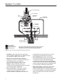
Downstream Control Line Connection
1/4 NPT (internal) in pilot body (downstream control line not required for pressure-loaded regulator)
Loading Pressure Connection
1/4 NPT (internal) in main valve diaphragm flange (this connection is factory-piped to the pilot on pilot-operated regulator)
Maximum Material Temperature Capabilities(2)
Metal Diaphragm and Seat
Cast Iron Construction: -40° to 406°F (-40° to 208°C)
Steel Construction: -20° to 500°F (-29° to 260°C)
Ethylenepropylene (EPR) Seat: -40° to 275°F
(-40° to 135°C)
Optional High-Temperature Steel or Stainless Steel Body: 650°F (343°C)
Pilot Spring Case Vent
3/32-inch (2,4 mm) drilled hole
1. Also see Installation section
2. Pressure/temperature limits in this Bulletin and any application codes must not be exceeded.
Approximate Weights
Cast iron, Steel, or Stainless steel Body
with Pilot: 20 pounds (9 kg)
Cast iron, Steel, or Stainless steel Body
without Pilot: 16 pounds (7 kg)
Table 1. Outlet Pressure Ranges
outlet pressure range
psig, (bar)
spring usage
spring part number
and color
5 to 70 (0,34 to 4,8)
Standard use up to 500°F (260°C)
High-Pressure and/or High
Temperature over 500°F (260°C)
spring wire
diameter,
inches (mm)
spring free
length,
inches (mm)
1E392627012 Green
0.170 (4,3)
2.00 (50,8)
20 to 150 (1,4 to 10,3)
1E392727142 Red
0.207 (5,3)
1.94 (49,3)
15 to 100 (1,0 to 6,9)
14B9941X012 Unpainted
0.192 (4,9)
80 to 250 (5,5 to 17,2)
14B9940X012 Unpainted
0.282 (7,2)
1.96 (49,8)
Table 2. Flow Coefficients(1)
wide-open for relief sizing
orifice size,
inches (mm)
cg
Cs
cv
9/16 (14)
170
8.5
5
3/4 (19)
240
12
7.1
c1
km
34
0.67
1. Cv = Cs x 20 ÷ C1
Table 3. IEC Sizing Coefficients
body size,
NPS (DN)
1/2 (15)
3/4 or 1 (20 or 25)
orifice size, inches (mm)
9/16 (14)
xT
0.73
FD
0.38
0.44
3/4 (19)
Fl
0.82
xT
FD
Fl
---0.73
0.38
0.82
3