1
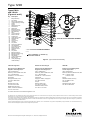
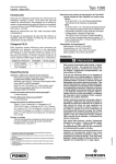
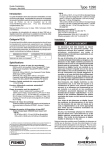
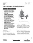
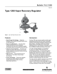
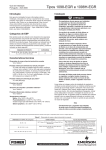
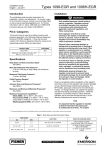
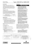
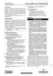
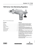
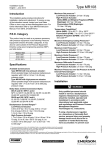
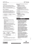
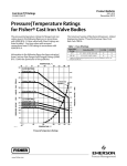
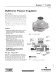
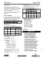
Installation Guide
English – February 2012
Type 1290
This installation guide provides instructions for
installation, startup, and adjustment. To receive a copy
of the instruction manual, contact your local Sales Office
or view a copy at www.fisherregulators.com. For further
information refer to: Type 1290 Instruction Manual,
form 5308, D101645X012.
Proof Test Pressure
All Pressure Retaining Components have been proof
tested per Directive 97/23/EC - Annex 1, Section 7.4.
Type 95H Supply Pressure Settings(1)
PILOT
TYPE
TYPE 1098-EGR MAIN VALVE WITH
GREEN SPRING, DN / NPS
25, 50, 80, or 100 /
1, 2, 3, or 4
bar
psig
150 / 6
bar
SPRING
COLOR
psig
The Type 1290 vapor recovery regulator is a self-contained,
pilot-operated regulator used for vapor recovery of
blanketing gas.
Y291AL
0.55
8
0.90
13
Black
P.E.D. Categories
Y291A
0.55
0.55
0.62
0.69
8
8
9
10
0.90
0.90
0.97
0.97
13
13
14
14
Orange
Red
Unpainted
Yellow
0.76
0.97
1.0
11
14
15
1.0
1.2
1.4
15
18
20
Green
Light Blue
Black
This product may be used as a pressure accessory with
pressure equipment in the following Pressure Equipment
Directive 97/23/EC categories. It may also be used
outside of the Pressure Equipment Directive using sound
engineering practice (SEP) per table below.
PRODUCT SIZES
DN 25 / NPS 1
DN 50, 80, 100, and 150 /
NPS 2, 3, 4, and 6
CATEGORIES
SEP
II
FLUID TYPE
1
Specifications
Body Size and End Connection Style
BODY SIZE
MAIN VALVE END CONNECTION STYLE
NPS
DN
Cast Iron
1 or 2
25 or 50
NPT, CL125 FF,
or CL250 RF
flanged
3, 4, or 6
80, 100,
or 150
CL125 FF or
CL250 RF flanged
8 x 6 or
12 x 6
200 x 150 or
300 x 150
----
WCC Steel or
CF8M Stainless Steel
NPT, SWE, BWE,
CL150 RF, CL300 RF,
CL600 RF, or
PN 16/25/40 flanged
BWE, CL150 RF,
CL300 RF, CL600 RF, or
PN 16 flanged
BWE, CL150 RF,
CL300 RF, CL600 RF, or
PN 25 flanged
Maximum Main Valve Inlet Pressure(1)
1.4 bar / 20 psig
Maximum Differential Pressure(1)
2.4 bar / 35 psi
Outlet (Control) Pressure Ranges(1)(2)
Type Y291AL:
1 to 4 mbar / 0.5 to 1.5-inches w.c.(3)
Type Y291A:
2 to 6 mbar / 1 to 2.5-inches w.c.(3)(4)
5 to 17 mbar / 2 to 7-inches w.c.(3)(5)
10 to 35 mbar / 4 to 14-inches w.c.
30 to 70 mbar / 12 to 28-inches w.c.
0.69 to 0.17 bar / 1.0 to 2.5 psig
0.17 to 0.31 bar / 2.5 to 4.5 psig
0.31 to 0.48 bar / 4.5 to 7 psig
1. The pressure/temperature limits in this Installation Guide and any applicable standard or code limitation should not be exceeded.
2. Spring ranges based on pilot being installed with the spring case pointed down.
3. Do not use fluorocarbon (FKM) diaphragm with this spring at diaphragm
temperatures lower than 16°C / 60°F.
4. When using a fluorocarbon (FKM) diaphragm, the minimum outlet pressure is
5 mbar / 2-inches w.c.
5. When using a fluorocarbon (FKM) diaphragm, the minimum outlet pressure is
6 mbar / 2.5-inches w.c.
Temperature Capabilities(1)
Nitrile (NBR) / Neoprene (CR):
-29° to 82°C / -20° to 180°F
Fluorocarbon (FKM):
For Inches w.c. Setpoints:
4° to 149°C / 40° to 300°F
For psig Setpoints:
-18° to 149°C / 0° to 300°F
Perfluoroelastomer (FFKM):
-29° to 149°C / -20° to 300°F
Ethylenepropylene (EPDM):
-29° to 135°C / -20° to 275°F
Installation
!
Warning
Only qualified personnel should install
or service a backpressure regulator.
Backpressure regulators should be
installed, operated, and maintained
in accordance with international and
applicable codes and regulations, and
Emerson Process Management Regulator
Technologies, Inc. instructions.
If using a backpressure regulator on a
hazardous or flammable fluid service,
personal injury and property damage could
occur due to fire or explosion of vented fluid
that may have accumulated. To prevent
such injury or damage, provide piping
or tubing to vent the fluid to a safe, wellventilated area or containment vessel. Also,
when venting a hazardous fluid, the piping
or tubing should be located far enough
away from any buildings or windows so
to not create a further hazard, and the
vent opening should be protected against
anything that could clog it.
Personal injury, equipment damage, or
leakage due to escaping fluid or bursting of
www.fisherregulators.com
D101645XUS2
Introduction
Type 1290
pressure-containing parts may result if this
backpressure regulator is overpressured
or is installed where service conditions
could exceed the limits given in the
Specifications section, or where conditions
exceed any ratings of the adjacent piping
or piping connections.
specified, the control spring is set at approximately the
midpoint of the spring range, so an initial adjustment
may be required to give the desired result. With proper
installation completed and relief valves properly adjusted,
slowly open the upstream and downstream shutoff valves
(if applicable).
To avoid such injury or damage, provide
pressure-relieving or pressure-limiting
devices (as required by the appropriate
code, regulation, or standard) to prevent
service conditions from exceeding limits.
Adjustment
Additionally, physical damage to the
backpressure regulator could result in
personal injury and property damage due
to escaping fluid. To avoid such injury and
damage, install the backpressure regulator
in a safe location.
Clean out all pipelines before installation of the backpressure
regulator and check to be sure the backpressure regulator
has not been damaged or has collected foreign material
during shipping. For NPT bodies, apply pipe compound to
the external pipe threads. For flanged bodies, use suitable
line gaskets and approved piping and bolting practices.
Install the backpressure regulator in any position desired,
unless otherwise specified, but be sure flow through the body
is in the direction indicated by the arrow on the body.
Note
It is important that the backpressure
regulator be installed so that the vent hole in
the spring case is unobstructed at all times.
For outdoor installations, the backpressure
regulator should be located away from
vehicular traffic and positioned so that water,
ice, and other foreign materials cannot enter
the spring case through the vent. Avoid
placing the backpressure regulator beneath
eaves or downspouts, and be sure it is above
the probable snow level.
Overpressure
The recommended pressure limitations are stamped on
the regulator nameplate. Some type of overpressure
protection is needed if the actual inlet pressure
exceeds the maximum operating outlet pressure rating.
Overpressure protection should also be provided if the
regulator inlet pressure is greater than the safe working
pressure of the downstream equipment.
Regulator operation below the maximum pressure
limitations does not preclude the possibility of damage from
external sources or debris in the line. The regulator should
be inspected for damage after any overpressure condition.
Startup
The backpressure regulator control spring is factory
set at a setpoint specified in the order. If no setpoint is
2
To change the outlet pressure, remove closing cap or
loosen the locknut and turn the adjusting screw clockwise
to increase outlet pressure or counterclockwise to
decrease pressure. Monitor the outlet pressure with a
test gauge during the adjustment. Replace closing cap or
tighten the locknut to maintain the desired setting.
Taking Out of Service (Shutdown)
!
Warning
To avoid personal injury resulting from
sudden release of pressure, isolate the
backpressure regulator from all pressure
before attempting disassembly.
Parts List
Design Type EGR
Type 1098 Actuator,
Main Valve (Figure 1) Size 40 (Figure 2)
Key Description
Key Description
1
2
3
3
4
5
6
7
1
2
3
4
5
6
7
8
9
10 11 12
13 27
28
56 57
Body
Body Flange
Cap Screw
Stud Bolt
Gasket
Lower Indicator Fitting
O-ring Retainer
Travel Indicator
Stem O-Ring
8 Hex Nut
9 Main Valve Spring
10 Lower Indicator Stem
11 Cage
12 Port Seal
13 Seat Ring
15 Upper Seal
16 Valve Plug
17 Cage O-Ring
18 Indicator Scale
19 Travel Indicator Protector
21 Indicator Fitting O-ring
22 Flange Nut
23 E-Ring
24 Drive Screw
25 Flow Arrow
27 Indicator Plug
28 Spring Seat
31 Pipe Plug
35 Indicator Fitting
36 Back-up Ring
37 Travel Indicator O-ring
Lower Diaphragm Case
Upper Diaphragm Case
Bonnet
Cap Screws
Casing O-Ring
Stem O-Ring
Diaphragm
Diaphragm Plate
Stem Cap Screw
Cap Screw
Hex Nut
Stem
Nameplate
Type Y602-12 Vent Assembly
Grease Fitting
Bearing
Wiper Ring
Type 95H Regulator
(Figure 3)
Key Description
1
2
3
4
5
6
7
8
9
10
11
12
15
16
17
20
Regulator Body
Spring Case
Orifice
Valve Plug
Valve Plug Guide
Stem Assembly
Stem Guide Bushing
Lower Spring Seat
Upper Spring Seat
Valve Plug Spring
Regulator Spring
Diaphragm
Adjusting Screw
Cap Screw
Jam Nut
Pitot Tube
Type 1290
6
19
8
18
10
3
28
56
12
57
5
27
2
13
7
4
9
1
11
10
22
37
8
7
35
21
5
6
36
3
2
31
24
4
26
20
15
23
28
9
17
11
16
13
12
24
1
25
34A5692
35A3167_E
Figure 1. Type EGR Main Valve Assembly
Figure 2. Type 1098 Actuator Assembly
26
11
15
6
8
17
L
16
9
2
12
7
1
3
4
20
6
22
18
S
49
L
13
10
36
21
19
20
25
10
31
33
5
44
1
43
5
30A7022_B
3
4
45
8
16
7
17
14
12
S
11
S
41
42
S
47B9751_E
- apply lubricant (L) / sealant (S)
Figure 3. Type 95H Supply Pressure Regulator Assembly
Figure 4. Type Y291AL Pilot Interior Assembly
3
Type 1290
Types Y291A
and Y291AL
(Figures 4 and 5)
Key Description
1
2
3
4
5
6
7
8
10 11 12 13 14
16
17 18
19 20
21 22
23 24
25
26
31
33 35
36
38
41 42 43 44 45 49 50 Body Assembly
Cap Screw
Spring Case Assembly
Lower Diaphragm Casing
Orifice
Spring
Diaphragm Head
Pusher Post
Diaphragm
Body Seal O-ring
Insert Seal O-ring
Disk Assembly
Stem
Lever Assembly
Machine Screw
Guide Insert
Upper Spring Seat
Adjusting Nut
Hex Nut
Closing Cap
Hex Nut
Cap Screw
Closing Cap Gasket
Vent Assembly
Throat Seal O-ring
Machine Screw
Adjusting Screw
Washer
Cap Screw
Back Disk Spring
Back Body Seal O-ring
Back Body Cap
Disk Spacer
Lower Head Gasket
Backup Ring
Heavy Diaphragm
Head Assembly
L
S
S
S
S
L
TYPE Y291A PILOT exTERIOR ASSEMBLY
TYPE Y291A PILOT INTERIOR ASSEMBLY
47B9750_E
- apply lubricant (L) / sealant (S)
PARTS NOT SHOWN 23
Figure 5. Type Y291A Pilot Assembly
Industrial Regulators
Natural Gas Technologies
TESCOM
Emerson Process Management
Regulator Technologies, Inc.
Emerson Process Management
Regulator Technologies, Inc.
Emerson Process Management
Tescom Corporation
USA - Headquarters
McKinney, Texas 75069-1872, USA
Tel: +1 800 558 5853
Outside U.S. +1 972 548 3574
USA - Headquarters
McKinney, Texas 75069-1872, USA
Tel: +1 800 558 5853
Outside U.S. +1 972 548 3574
USA - Headquarters
Elk River, Minnesota 55330-2445, USA
Tels: +1 763 241 3238
+1 800 447 1250
Asia-Pacific
Shanghai 201206, China
Tel: +86 21 2892 9000
Asia-Pacific
Singapore 128461, Singapore
Tel: +65 6770 8337
Europe
Selmsdorf 23923, Germany
Tel: +49 38823 31 287
Europe
Bologna 40013, Italy
Tel: +39 051 419 0611
Europe
Bologna 40013, Italy
Tel: +39 051 419 0611
Gallardon 28320, France
Tel: +33 2 37 33 47 00
Asia-Pacific
Shanghai 201206, China
Tel: +86 21 2892 9499
Middle East and Africa
Dubai, United Arab Emirates
Tel: +971 4811 8100
For further information visit www.fisherregulators.com
The Emerson logo is a trademark and service mark of Emerson Electric Co. All other marks are the property of their prospective owners. Fisher is a mark owned by Fisher Controls
International LLC, a business of Emerson Process Management.
The contents of this publication are presented for informational purposes only, and while every effort has been made to ensure their accuracy, they are not to be construed as warranties
or guarantees, express or implied, regarding the products or services described herein or their use or applicability. We reserve the right to modify or improve the designs or specifications
of such products at any time without notice.
Emerson Process Management does not assume responsibility for the selection, use or maintenance of any product. Responsibility for proper selection, use and maintenance of any
Emerson Process Management product remains solely with the purchaser.
©Emerson Process Management Regulator Technologies, Inc., 2002, 2012; All Rights Reserved