1
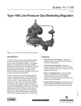
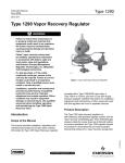
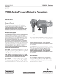
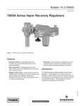
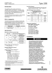
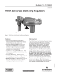
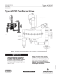
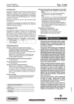
Bulletin 74.2:1290
May 2013
Type 1290 Vapor Recovery Regulator
W7427_1
Figure 1. Type 1290 Vapor Recovery Valve
Introduction
• Quick-Change Trim Package — Tested trim
packages can be ordered and stocked ahead of time
for fast replacement.
• Easy In-Line Maintenance — Top-entry design
reduces maintenance time and manpower
requirements; trim parts can be inspected, cleaned,
and replaced without removing the body from the line.
• In-Service Travel Inspection — Standard travel
indicator assembly with protective cover permits
periodic inspection of plug travel without removing
regulator from service.
• High Accuracy — Total proportional band of
0.25-inch w.c. / 0.62 mbar or less at lower
set pressures.
• Proven Technology — Time-proven regulator
technology has been adapted to meet the
specific requirements of vapor recovery
(depadding) applications.
The Type 1290 vapor recovery regulator controls vessel
blanketing gas pressure when the vessel is being filled
with fluid or when ambient temperature causes the vapor
gas to expand. The system monitors the increasing
blanket pressure and throttles open to pass excess
blanketing gas into a vapor disposal or reclamation system
thus controlling the desired set pressure of the vessel.
The vapor recovery regulator is not intended to
be used as an ASME certified relief device for
overpressure protection. It is to be used as part of
the gas blanketing system to control the outflow of
blanketing gas under normal conditions and to collect
vessel vapors for the vapor disposal or reclamation
system. You should provide alternate methods of
emergency overpressure protection per the American
Petroleum Institute Standard 2000 (API 2000).
The vapor recovery regulator responds to any changes
in the blanket gas pressure and throttles open or
closed to control the flow of the blanket gas out of the
vessel. A vacuum source on the outlet of the regulator
is usually necessary to ensure flow of low pressure
www.fisherregulators.com
D101964X012
Features
Bulletin 74.2:1290
Specifications
Body Size and End Connection Styles(1)
MAIN VALVE END CONNECTION STYLE
BODY SIZE,
NPS / DN
Flow Coefficients
See Table 5
Cast Iron
WCC Steel or
CF8M Stainless Steel
Control Line Connection
1/2 NPT
1 or 2 /
25 or 50
NPT, CL125 FF or
CL250 RF flanged
NPT, SWE, BWE, CL150 RF,
CL300 RF, CL600 RF,
or PN 16/25/40 flanged
Exhaust Line Connection
3/4 NPT
3, 4, or 6 /
80, 100, or 150
CL125 FF or
CL250 RF flanged
BWE, CL150 RF, CL300 RF,
CL600 RF, or PN 16 flanged
8 x 6 or 12 x 6 /
200 x 150 or 300 x 150
----
BWE, CL150 RF,
CL300 RF, CL600 RF,
or PN 25 flanged
Supply Pressure and Spring Case Connections
1/4 NPT
Orifice Diameters and Travels
BODY SIZE
Construction Materials
See Table 1
Maximum Main Valve Inlet Pressures(2)
See Table 3
Maximum Differential Pressure
35 psi / 2.4 bar
Control Pressure Ranges(2)
See Table 2
Type 95H Supply Pressure Settings
PILOT
TYPE
TYPE 1098-EGR MAIN VALVE WITH
GREEN SPRING, NPS / DN
SPRING
COLOR
1, 2, 3, or 4 /
25, 50, 80, or 100
6 or 8 x 6 /
150 or 200 x 150
Y291AL
8 psig / 0.55 bar
13 psig / 0.90 bar
Black
Y291A
8 psig / 0.55 bar
8 psig / 0.55 bar
9 psig / 0.62 bar
10 psig / 0.69 bar
13 psig / 0.90 bar
13 psig / 0.90 bar
14 psig / 0.97 bar
14 psig / 0.97 bar
Orange
Red
Unpainted
Yellow
11 psig / 0.76 bar
14 psig / 0.97 bar
15 psig / 1.0 bar
15 psig / 1.0 bar
18 psig / 1.2 bar
20 psig / 1.4 bar
Green
Light blue
Black
Type Y291A or Y291AL Pilot Orifice Diameter
3/8-inch / 9.5 mm
Flow Capacities
See Table 4
PORT DIAMETER
TRAVEL
NPS
DN
Inch
mm
Inch
mm
1
2
3
25
50
80
1-5/16
2-3/8
3-3/8
33
60
86
3/4
1-1/8
1-1/2
19
29
38
4
6
8x6
12 x 6
100
150
200 x 150
300 x 150
4-3/8
7-3/16
7-3/16
7-3/16
111
183
183
183
2
2
2
2
51
51
51
51
Material Temperature Capabilities(2)
Nitrile (NBR):
-20 to 180°F / -29 to 82°C
Fluorocarbon (FKM):
For Inches w.c. Setpoints: 40 to 300°F / 4 to 149°C
For psig Setpoints: 0 to 300°F / -18 to 149°C
Ethylenepropylene (EPDM):
-20 to 275°F / -29 to 135°C
Perfluoroelastomer (FFKM):
-20 to 300°F / -29 to 149°C
Approximate Weights
NPS 1 / DN 25: 85 pounds / 39 kg
NPS 2 / DN 50: 100 pounds / 45 kg
NPS 3 / DN 80: 145 pounds / 66 kg
NPS 4 / DN 100: 195 pounds / 88 kg
NPS 6 / DN 150: 380 pounds / 172 kg
NPS 8 x 6 / DN 200 x 150: 740 pounds / 336 kg
NPS 12 x 6 / DN 300 x 150: 1265 pounds / 574 kg
1. End connections for other than U.S. standards can usually be provided. Consult your local Sales Office.
2. The pressure/temperature limits in this Bulletin and any applicable standard or code limitation should not be exceeded.
blanket gas out of the vessel into a vapor disposal or
reclamation system. The higher the vacuum pressure
of the vacuum source, the higher the flow capacity of
the vapor recovery regulator.
regulator controls vessel blanketing gas pressure
when the vessel is being filled with fluid or
when ambient temperature causes the vapor gas
to expand.
Principle of Operation
The system monitors the increasing blanket pressure
and throttles open to pass excess blanketing gas into
a vapor recovery system thus controlling the desired
set pressure of the vessel.
The Type 1290 vapor recovery regulator serves as
a vessel vapor recovery system. The Type 1290
2
Bulletin 74.2:1290
TYPE 1098-EGR
MAIN VALVE
VAPOR RECOVERY
VACUUM SOURCE
CONTROL LINE
TYPE Y291A PILOT
FIXED RESTRICTION
SETPOINT
ADJUSTMENT
EXHAUST LINE
VAPOR PRESSURE
TANK
TYPE 95H SUPPLY
REGULATOR
E0063
VACUUM PRESSURE
ATMOSPHERIC PRESSURE
LOADING PRESSURE
LOADING PRESSURE
TANK PRESSURE
INTERMEDIATE PRESSURE
INTERMEDIATEVACUUM
PRESSURE
PRESSURE
ATMOSPHERICTANK
PRESSURE
PRESSURE
Figure 2. Operational Schematic
Table 1. Construction Materials(1)
MAIN VALVE
Body and
Body Flange
Plug and
Seat Ring
Spring
Cage
SIZE 40
ACTUATOR
PILOT
SUPPLY
REGULATOR
Cast iron
416 Stainless
steel
Steel
Cast iron
Steel
Ductile iron
Cast iron
WCC Steel
416 Stainless
steel
Steel
Steel
Steel
Ductile iron
WCC Steel
CF8M
Stainless steel
316 Stainless
steel
Inconel®
X-750
316 Stainless
steel
CF8M Stainless CF8M Stainless
Stainless steel
Whisper
steel
steel
Trim™ Cage
DIAPHRAGMS
O-RINGS AND SEALS
Nitrile (NBR),
Fluorocarbon (FKM),
or Ethylenepropylene
(EPDM)
Nitrile (NBR),
Fluorocarbon (FKM),
Ethylenepropylene
(EPDM), or
Perfluoroelastomer
(FFKM)
1. Special construction materials are offered for your system compatibility. Contact your local Sales Office for additional information.
Inconel® is a mark owned by Special Metals Corporation.
3
Bulletin 74.2:1290
Table 2. Control Pressure Ranges
PILOT
TYPE
CONTROL PRESSURE RANGES(1)
SPRING
COLOR
Y291AL
0.5 to 1.5-inches w.c. / 1 to 4 mbar(2)
Black
Y291A
1 to 2.5-inches w.c. / 2 to 6 mbar(2)(3)
2 to 7-inches w.c. / 5 to 17 mbar(2)(4)
4 to 14-inches w.c. / 10 to 35 mbar
12 to 28-inches w.c. / 30 to 70 mbar
1.0 to 2.5 psig / 0.07 to 0.17 bar
2.5 to 4.5 psig / 0.17 to 0.31 bar
4.5 to 7 psig / 0.31 to 0.48 bar
Orange
Red
Unpainted
Yellow
Green
Light blue
Black
1.
2.
3.
4.
SPRING PART
NUMBER
SPRING WIRE
DIAMETER
BUILDUP TO
WIDE-OPEN
SPRING FREE
LENGTH
Inch
mm
Inch
mm
1B413627222 0.25-inch w.c. / 0.60 mbar
0.075
1.90
2.19
56.0
1B558527052
1B653827052
1B653927022
1B537027052
1B537127022
1B537227022
1B537327052
0.072
0.085
0.100
0.114
0.156
0.187
0.218
1.83
2.20
2.70
2.90
4.00
4.80
5.40
3.78
3.63
3.75
4.31
4.06
3.94
3.98
96.0
92.0
95.0
109
103
100
101
0.25-inch w.c. / 0.60 mbar
0.25-inch w.c. / 0.60 mbar
0.25-inch w.c. / 0.60 mbar
1.4-inch w.c. / 3 mbar
2.8-inch w.c. / 7 mbar
4.2-inch w.c. / 10 mbar
5.5-inch w.c. / 14 mbar
Spring ranges based on pilot being installed with the spring case pointed down.
Do not use Fluorocarbon (FKM) diaphragm with this spring at diaphragm temperatures lower than 60°F / 16°C.
When using a Fluorocarbon (FKM) diaphragm, the minimum outlet pressure is 2-inches w.c. / 5 mbar.
When using a Fluorocarbon (FKM) diaphragm, the minimum outlet pressure is 2.5-inches w.c. / 6 mbar.
Table 3. Maximum Main Valve Inlet Pressures
MAXIMUM INLET PRESSURES, psig / bar
Type 1098-EGR Main Valve with Green Spring
PILOT TYPE
Y291AL
Y291A
SPRING COLOR
NPS 1 / DN 25
NPS 2 / DN 50
NPS 3 / DN 80
NPS 4 / DN 100
NPS 6, 8 x 6, or 12 x 6 /
DN 150, 200 x 150, or 300 x 150
5.5 / 0.38
5 / 0.35
4 / 0.28
3 / 0.21
3.5 / 0.24
Black
5.5 / 0.38
5 / 0.35
4 / 0.28
3 / 0.21
3.5 / 0.24
Orange
5.5 / 0.38
5 / 0.35
4 / 0.28
3 / 0.21
3.5 / 0.24
Red
6.5 / 0.45
6 / 0.41
5 / 0.35
4 / 0.28
4.5 / 0.31
Unpainted
7.5 / 0.52
7 / 0.48
6 / 0.41
5 / 0.35
4.5 / 0.31
Yellow
8.5 / 0.59
8 / 0.55
7 / 0.48
6 / 0.41
5.5 / 0.38
Green
11.5 / 0.79
11 / 0.76
10 / 0.69
9 / 0.62
8.5 / 0.59
Light Blue
12.5 / 0.86
12 / 0.83
11 / 0.76
10 / 0.69
10.5 / 0.72
Black
Table 4. Flow Capacities for Type 1290 Vapor Recovery Regulators
PILOT
TYPE
PILOT
SPRING
COLOR
CONTROL
PRESSURE
BUILDUP OVER
CONTROL
PRESSURE TO
WIDE-OPEN(1)
DOWNSTREAM
VACUUM
PRESSURE
Y291AL
Black
0.5-inch w.c. /
1 mbar
0.25-inch w.c. /
0.60 mbar
0 psig / 0 bar
2.5 psig / 0.17 bar
5 psig / 0.34 bar
600 / 16.1
5600 / 150
7300 / 196
2300 / 61.6
19,900 / 533
25,800 / 691
4900 / 131
43,100 / 1155
55,700 / 1493
7600 / 204
66,900 / 1793
86,700 / 2324
14,600 / 391
124,500 / 3337
160,600 / 4304
1-inch w.c. /
2 mbar
0.25-inch w.c. /
0.60 mbar
0 psig / 0 bar
2.5 psig / 0.17 bar
5 psig / 0.34 bar
700 / 18.8
5700 / 153
7400 / 198
2700 / 72.4
10,000 / 268
25,900 / 694
5900 / 158
43,200 / 1158
55,800 / 1495
9200 / 247
67,000 / 1796
86,800 / 2326
17,700 / 474
126,700 / 3396
160,800 / 4309
2-inches w.c. /
5 mbar
0.25-inch w.c. /
0.60 mbar
0 psig / 0 bar
2.5 psig / 0.17 bar
5 psig / 0.34 bar
1100 / 29.5
5800 / 155
7400 / 198
3900 / 105
20,200 / 541
26,000 / 697
8400 / 225
43,500 / 1166
56,000 / 1501
13,000 / 348
67,600 / 1812
87,200 / 2337
25,000 / 670
127,700 / 3422
161,500 / 4328
4-inches w.c. /
10 mbar
0.25-inch w.c. /
0.60 mbar
8-inches w.c. /
20 mbar
0.25-inch w.c. /
0.60 mbar
15-inches w.c. /
37 mbar
0.25-inch w.c. /
0.60 mbar
1 psig /
0.07 bar
0.05 psig /
3 mbar
3 psig /
0.21 bar
0.15 psig /
10 mbar
5 psig /
0.34 bar
0.15 psig /
10 mbar
7 psig /
0.48 bar
0.20 psig /
14 mbar
0 psig / 0 bar
2.5 psig / 0.17 bar
5 psig / 0.34 bar
0 psig / 0 bar
2.5 psig / 0.17 bar
5 psig / 0.34 bar
0 psig / 0 bar
2.5 psig / 0.17 bar
5 psig / 0.34 bar
0 psig / 0 bar
2.5 psig / 0.17 bar
5 psig / 0.34 bar
0 psig / 0 bar
2.5 psig / 0.17 bar
5 psig / 0.34 bar
0 psig / 0 bar
2.5 psig / 0.17 bar
5 psig / 0.34 bar
0 psig / 0 bar
2.5 psig / 0.17 bar
5 psig / 0.34 bar
1500 / 40.2
5800 / 155
7500 / 201
2100 / 56.3
6000 / 161
7600 / 204
2900 / 77.7
6300 / 169
7900 / 212
4000 / 107
6800 / 182
8100 / 217
7000 / 188
8700 / 233
9600 / 257
9100 / 244
10,200 / 273
11,000 / 295
10,800 / 289
11,700 / 314
12,300 / 330
5300 / 142
20,500 / 549
26,300 / 705
7400 / 198
21,000 / 563
26,800 / 718
10,100 / 271
22,000 / 590
27,800 / 745
14,100 / 378
23,900 / 641
28,700 / 769
24,700 / 662
30,600 / 820
34,100 / 914
31,900 / 855
36,300 / 973
39,000 / 1045
38,200 / 1024
41,600 / 1115
43,800 / 1174
11,500 / 308
44,100 / 1182
56,600 / 1517
16,000 / 429
45,300 / 1214
57,700 / 1546
21,800 / 584
47,400 / 1270
59,800 / 1603
30,500 / 817
51,400 / 1378
61,800 / 1656
53,200 / 1426
66,000 / 1769
73,400 / 1967
68,600 / 1838
78,100 / 2093
83,900 / 2249
82,200 / 2203
89,500 / 2399
94,200 / 2525
17,800 / 477
68,500 / 1836
88,100 / 2361
24,800 / 665
70,400 / 1887
89,800 / 2407
33,800 / 906
73,600 / 1972
93,100 / 2495
47,200 / 1265
79,900 / 2141
96,200 / 2578
82,500 / 2211
102,700 / 2752
114,600 / 3071
106,700 / 2860
121,600 / 3259
131,000 / 3511
127,900 / 3428
139,700 / 3744
147,300 / 3948
34,200 / 917
129,400 / 3468
162,200 / 4347
47,600 / 1276
132,800 / 3559
166,200 / 4454
64,900 / 1739
138,700 / 3717
172,400 / 4620
90,300 / 2420
150,100 / 4023
177,200 / 4749
155,800 / 4175
190,700 / 5111
209,100 / 5604
199,500 / 5347
224,000 / 6003
327,400 / 8774
237,100 / 6354
255,300 / 6842
265,100 / 7105
Orange
Unpainted
Y291A
Yellow
Light blue
Black
1. Increased capacity is available at higher buildups.
4
CAPACITIES IN SCFH / Nm3/h OF 0.97 SPECIFIC GRAVITY NITROGEN
NPS 1 / DN 25 NPS 2 / DN 50 NPS 3 / DN 80 NPS 4 / DN 100 NPS 6 / DN 150
Body
Body
Body
Body
Body
Bulletin 74.2:1290
Table 5. Flow Coefficients
PIPING STYLE
Line Size Equals Body Size Piping
BODY SIZE,
NPS / DN
Linear Cage
Cg
Drilled Hole Whisper Trim™ Cage
Cv
Regulating Wide-Open Regulating Wide-Open
C1
Cg
Km
Cv
C1
Km
17.6
57.8
113
190
310
34.5
36.0
35.0
34.8
32.0
0.80
Regulating
Wide-Open
Regulating
Wide-Open
576
1970
3760
6280
9450
607
2080
3960
6610
9950
16.7
54.7
107
180
295
1 / 25
2 / 50
3 / 80
4 / 100
6 / 150
600
2280
4630
7320
12,900
632
2400
4880
7710
13,600
16.8
63.3
132
202
397
17.7
66.7
139
213
418
35.7
36.0
35.1
36.2
32.5
8x6/
200 x 150
18,480
19,450
578
608
32.0
10,660
11,220
305
321
35.0
12 x 6 /
300 x 150
21,180
22,290
662
697
32.0
11,050
11,630
316
332
35.0
0.70
PIPING STYLE
2:1 Line Size to Body Size Piping
BODY SIZE,
NPS / DN
Standard Linear Cage
Cg
Cv
Regulating Wide-Open Regulating Wide-Open
1 / 25
2 / 50
3 / 80
4 / 100
6 / 150
8x6/
200 x 150
12 x 6 /
300 x 150
Drilled Hole Whisper Trim Cage
C1
Cg
Km
Cv
C1
Km
16.4
55.1
110
180
306
34.0
35.1
34.2
35.2
31.7
0.80
Regulating
Wide-Open
Regulating
Wide-Open
529
1830
3630
6020
9240
557
1930
3830
6340
9730
15.6
52.3
106
171
291
568
2050
4410
6940
12,100
598
2160
4650
7310
12,800
17.2
59.6
128
198
381
18.1
62.8
135
209
404
33.0
34.4
34.4
35.0
31.7
17,370
18,280
543
571
32.0
10,020
10,550
286
301
35.0
19,900
20,950
622
655
32.0
10,380
10,930
297
312
35.0
0.70
Table 6. Flow Rate Conversions (Gas Flow Required to Displace Blanketing Gas with Pump-in of Liquid)
MULTIPLY MAXIMUM PUMP RATE IN
BY
TO OBTAIN
U.S. GPM
U.S. GPH
Barrels/hour
Barrels/day
8.021
0.1337
5.615
0.2340
SCFH air required(2)
1. For liquids with a flash point below 100°F / 38°C or normal boiling point below 300°F / 149°C, multiply the above calculated outbreathing requirement by 2.0.
2. To convert to Nm3/h, multiply SCFH by 0.0268.
Note
The Type 1290 Vapor Recovery Regulator
is not intended to be used as an ASME
certified relief device for overpressure
protection. It is to be used as part of
the gas blanketing system to control the
outflow of blanketing gas under normal
conditions and to collect vessel vapors
for the vapor recovery system. You
should provide alternate methods of
emergency overpressure protection.
The Type 1290 vapor recovery regulator responds to
any changes in the blanket gas pressure and throttles
open or closed to control the flow of the blanket gas
out of the vessel. A vacuum source on the outlet of
the regulator is usually necessary to ensure flow of low
pressure blanket gas out of the vessel into a vapor
recovery system. The higher the vacuum pressure of
the vacuum source, the higher the flow capacity of the
vapor recovery regulator.
The pressure of the blanket gas registers under
the diaphragm of the pilot. A Type 95H regulator
provides a constant loading pressure source to the
Type 1098-EGR main valve actuator. When the pilot
is closed, the loading pressure fills both sides of the
Type 1098 actuator through a fixed restriction.
The Type 1098-EGR main valve spring keeps the
main valve plug tightly shut off. When the vessel
blanket gas pressure reaches the setting of the
pilot spring, the pilot diaphragm moves, opening
the pilot valve disk and exhausting some of the
Type 1098-EGR’s actuator loading pressure through
the pilot orifice. This typically happens when the vessel
is being filled with liquid.
5
Bulletin 74.2:1290
Table 7. Gas Flow Required for Thermal Heating (Outbreathing) per API 2000 (Interpolate for intermediate sizes)
VESSEL CAPACITY
Barrels
Gallons
Liters
60
100
500
1000
2000
3000
4000
5000
10,000
15,000
20,000
25,000
30,000
35,000
40,000
45,000
50,000
60,000
70,000
80,000
90,000
100,000
120,000
140,000
160,000
2500
4200
21,000
42,000
84,000
126,000
168,000
210,000
420,000
630,000
840,000
1,050,000
1,260,000
1,470,000
1,680,000
1,890,000
2,100,000
2,520,000
2,940,000
3,360,000
3,780,000
4,200,000
5,040,000
5,880,000
6,720,000
9500
16,000
79,500
159,000
318,000
477,000
636,000
795,000
1,590,000
2,385,000
3,180,000
3,975,000
4,769,000
5,564,000
6,359,000
7,154,000
7,949,000
9,539,000
11,298,000
12,718,000
14,308,000
15,897,000
19,077,000
22,256,000
25,436,000
180,000
7,560,000
28,615,000
SCFH / Nm3/h AIR FLOW RATE REQUIRED
Flash Point is Equal to or Above 100°F / 38°C or
Flash Point is Below 100°F / 38°C or
Normal Boiling Point is Equal to or Above 300°F / 149°C
Normal Boiling Point is Below 300°F / 149°C
40 / 1.07
60 / 1.61
60 / 1.61
100 / 2.68
300 / 8.04
500 / 13.4
600 / 16.1
1000 / 26.8
1200 / 32.2
2000 / 53.6
1800 / 48.2
3000 / 80.4
2400 / 64.3
4000 / 107
3000 / 80.4
5000 / 134
6000 / 161
10,000 / 268
9000 / 241
15,000 / 402
12,000 / 322
20,000 / 536
15,000 / 402
24,000 / 643
17,000 / 456
28,000 / 750
19,000 / 509
31,000 / 831
21,000 / 563
34,000 / 911
23,000 / 616
37,000 / 992
24,000 / 643
40,000 / 1072
27,000 / 724
44,000 / 1179
29,000 / 777
48,000 / 1286
31,000 / 831
52,000 / 1394
34,000 / 911
56,000 / 1501
36,000 / 965
60,000 / 1608
41,000 / 1099
68,000 / 1822
45,000 / 1206
75,000 / 2010
50,000 / 1340
82,000 / 2198
54,000 / 1447
The small fixed restriction maintains a higher loading
pressure on the bottom of the Type 1098 actuator. The
pressure differential across the main valve diaphragm
moves the diaphragm upward causing the main valve
to open which allows the blanket gas to flow out to
the vapor recovery system vacuum source, hence
controlling the vessel blanket pressure.
When the vessel blanket gas pressure begins to stabilize,
the pilot spring throttles the pilot disk closed. This allows
the loading pressure source to fill both sides of the
Type 1098 actuator through the fixed restriction. This
equalizes the pressure acting on the diaphragm, thus
allowing the main valve spring to close the main valve plug.
Sizing Blanketing Systems
When sizing a gas vapor recovery regulator system, you
must consider the volume of blanketing gas that must be
displaced from the vessel when either filling the vessel
with liquid (pump-in) or the expansion of vapors inside
the vessel during atmospheric thermal heating.
Using the established procedures from American
Petroleum Institute Standard 2000 (API 2000), determine
the flow rate for outbreathing.
1. D
etermine the flow rate of blanketing gas
displaced when liquid is being pumped into the
vessel (see Table 6).
2. D
etermine the gas flow rate due to outbreathing
caused by atmospheric thermal heating (see Table 7).
6
90,000 / 2412
3. A
dd the requirements of 1 and 2 and select a vapor
recovery regulator size based on total capacity
required from Table 4.
Sample Sizing Problem for Vapor
Recovery Applications:
Vessel Capacity . . . . . . . . . . . . . . . . . . . . 1000 barrels
Pump in Capacity . . . . . . . . . . . . . . . . . . 20 GPM / 75.7 lpm
Inlet Pressure Source . . . . . 60 psig / 4.1 bar nitrogen
Desired Blanket Setpoint . . . . 0.5-inch w.c. / 1 mbar
Desired Vapor Recovery Setpoint . . . 2-inches w.c. / 5 mbar
Vapor Recovery Vacuum Source . . . 5-inches Hg / 169 mbar
Fluid . . . . . . . . . . . . . . . . . . . . . . . . . . . . . . . . . Hexane
Boiling Point . . . . . . . . . . . . . . . . . . . . . . 155°F / 68°C
1. From Table 6 the desired air flow rate due to
pump in equals 20 GPM x 8.021 x 2 = 320 SCFH /
8.58 Nm3/h air.
2. F
rom Table 7 the desired air flow rate = 1000 SCFH /
26.8 Nm3/h air due to thermal heating.
3. Total required flow rate = 1000 SCFH air +
320 SCFH = 1320 SCFH / 35.4 Nm3/h air. This
converts to nitrogen requirements of 1340 SCFH /
35.9 Nm3/h.
Capacity Information
Table 4 gives typical nitrogen regulating capacities at
selected inlet pressures and outlet pressure settings.
Flows are in SCFH (at 60°F and 14.7 psia) and Nm3/h
Bulletin 74.2:1290
Table 8. Materials Compatibility
CORROSION INFORMATION
302 or 304
Stainless Steel
CF8M or 316
Stainless Steel
416 Stainless
Steel
Monel®(1)
Hastelloy® C(2)
B
A
B
A
A
Methanol
Methyl Ethyl Ketone
Natural Gas
Nitric Acid
Petroleum Oils (Refined)
A
A
A
C
A
A
A
A
C
A
A
A
A
A
A
A
A
A
B
A
A
A
A
C
A
A
A
A
C
A
A
A
A
B
A
A
A
A
A
A
Phosphoric Acid (Air Free)
Phosphoric Acid Vapors
Potassium Chloride
Potassium Hydroxide
Propane
C
C
B
B
A
C
C
B
B
A
A
B
A
A
A
A
A
A
B
A
C
C
C
B
A
B
C
B
A
A
A
I.L.
A
A
A
A
A
A
A
B
A
A
A
A
A
Silver Nitrate
Sodium Acetate
Sodium Carbonate
Sodium Chloride
Sodium Chromate
C
A
A
C
A
C
A
A
C
A
A
B
A
B
A
A
A
A
B
A
B
A
B
B
A
C
A
A
A
A
A
A
A
A
A
C
A
C
C
C
A
A
A
C
C
A
A
A
B
A
Sodium Hydroxide
Stearic Acid
Sulfur
Sulfur Dioxide (Dry)
Sulfur Trioxide (Dry)
A
A
A
A
A
A
C
A
A
A
A
A
A
A
A
A
A
A
A
A
B
B
A
B
B
A
B
A
A
A
A
A
A
A
A
B
A
A
B
A
C
B
A
A
A
A
B
B
C
A
A
A
A
A
A
Sulfuric Acid (Aerated)
Sulfuric Acid (Air Free)
Sulfurous Acid
Trichloroethylene
Water (Boiler Feed)
C
C
C
B
B
C
C
C
B
C
C
C
B
B
A
C
C
B
A
A
C
C
C
B
B
C
B
C
A
A
A
A
A
A
A
A
A
A
A
B
A
A
A
A
B
B
A
A
A
C
A
A
A
A
A
A
A
I.L.
A
A
Water (Distilled)
Water (Sea)
Zinc Chloride
Zinc Sulfate
----
A
B
C
C
-
A
B
C
C
-
A
B
C
A
-
A
B
C
A
-
B
C
C
B
-
A
A
C
A
-
A
A
A
A
-
B
A
A
A
C
A
A
A
A
C
I.L.
I.L.
A
A
C
A
A
A
A
C
A
A
A
A
B
----------------
-
-
-
-
-
-
-
Hastelloy® C(2)
C
A
A
C
A
Monel®(1)
C
A
B
C
A
416 Stainless
Steel
C
A
A
A
A
CF8M or 316
Stainless Steel
C
A
A
A
A
302 or 304
Stainless Steel
C
A
A
C
A
Cast or
Ductile Iron
C
A
I.L.
C
A
Carbon Steel
Cast or
Ductile Iron
Material
Carbon Steel
Material
Acetic Acid (Air Free)
Acetic Acid Vapors
Acetone
Acetylene
Alcohols
C
C
A
A
A
C
C
A
A
A
B
A
A
A
A
B
A
A
A
A
C
C
A
A
A
B
A
A
A
A
A
A
A
A
A
Hydrochloric Acid (Air Free)
Hydrogen
Hydrogen Peroxide
Hydrogen Sulfide (Liquid)
Magnesium Hydroxide
Aluminum Sulfate
Ammonia
Ammonium Chloride
Ammonium Nitrate
Ammonium Sulfate
C
A
C
A
C
C
A
C
C
C
A
A
B
A
B
A
A
B
A
A
C
A
C
C
C
B
A
B
C
A
A
A
A
A
A
Ammonium Sulfite
Beer
Benzene (Benzol)
Benzoic Acid
Boric Acid
C
B
A
C
C
C
B
A
C
C
A
A
A
A
A
A
A
A
A
A
B
B
A
A
B
C
A
A
A
A
Butane
Calcium Chloride (Alkaline)
Carbon Dioxide (Dry)
Carbon Dioxide (Wet)
Carbon Disulfide
A
B
A
C
A
A
B
A
C
A
A
C
A
A
A
A
B
A
A
A
A
C
A
A
B
Carbon Tetrachloride
Carbonic Acid
Chlorine Gas (Dry)
Chlorine Gas (Wet)
Chlorine (Liquid)
B
C
A
C
C
B
C
A
C
C
B
B
B
C
C
B
B
B
C
C
Chromic Acid
Citric Acid
Coke Oven Gas
Copper Sulfate
Ether
C
I.L.
A
C
B
C
C
A
C
B
C
B
A
B
A
Ethyl Chloride
Ethylene
Ethylene Glycol
Formaldehyde
Formic Acid
C
A
A
B
I.L.
C
A
A
B
C
B
B
A
A
C
B
B
A
A
C
Fluid
Freon (Wet)
Freon (Dry)
Gasoline (Refined)
Glucose
Hydrochloric Acid (Aerated)
Fluid
1. Monel® is a mark owned by Special Metals Corporation.
A+--Best possible selection
2. Hastelloy® C is a mark owned by Haynes International, Inc.
A--Recommended
B--Minor to moderate effect. Proceed with caution.
C--Unsatisfactory
I.L.--Information lacking
- continued (at 0°C and 1.01325 bar) of 0.97 specific gravity
nitrogen. For gases of other specific gravities, multiply
the given capacity of nitrogen by 0.985, and divide by
the square root of the appropriate specific gravity of
the gas required. To determine regulating capacities
at pressure settings not given or to determine
wide-open flow capacities, use the following formula:
Q= 520
3417 ∆P
C P Sin
Deg
GT g 1
C1P1
where:
Cg = gas sizing coefficient from Table 5
C1 = Cg/Cv or 35 from Table 5
G = gas specific gravity (air = 1.0)
P1 = absolute inlet pressure, psia (add 14.7 psi
to gauge inlet pressure to obtain absolute
inlet pressure)
Q = flow rate, SCFH
T = absolute temperature in °R of gas at inlet
(°F + 460)
7
Bulletin 74.2:1290
Table 8. Materials Compatibility (continued)
FLUID INFORMATION
Material
Fluid
Neoprene (CR)
Nitrile (NBR)
Fluorocarbon
(FKM)
Acetic Acid (30%)
Acetone
Alcohol (Ethyl)
Alcohol (Methyl)
Ammonia (Anhydrous)
C
B
A
A+
A
B
C
A
A
C
B
C
B
C
C
A
A
A
A
A
A
A
A
A
A
Ammonia (Gas, Hot)
Benzene
Brine (Calcium Chloride)
Butadiene Gas
Butane (Gas)
Butane (Liquid)
B
C
A
B
A
B
C
C
A
C
A+
A
C
A
B
B
A
A
A
A
A
A
A
A
B
C
A
C
C
C
Carbon Tetrachloride
Chlorine (Dry)
Chlorine (Wet)
Coke Oven Gas
Ethyl Acetate
C
C
C
C
C
C
C
C
B
C
A
A
A
A+
C
A
A
A
A
A
C
C
C
C
B
Ethylene Glycol
Freon 11
Freon 12
Freon 22
Freon 114
A
B
A+
A+
A
A
A
A
C
A
A
A+
B
C
B
A
A
A
A
A
A
C
B
A
A
Gasoline
Hydrogen Gas
Hydrogen Sulfide (Dry)
Hydrogen Sulfide (Wet)
Jet Fuel (JP-4)
B
A
A
B
C
A+
A
C
C
A
A
A
C
C
A
A
A
A
A
A
C
A
A
A
I.L.
Natural Gas
Natural Gas + H2S (Sour Gas)
Nitric Acid (20%)
Nitric Acid (50 to 100%)
Nitrogen
A
A
B
C
A
A+
B
C
C
A
A
C
A
A
A
A
A
A
A
A
C
C
C
C
A
Oil (Fuel)
Propane
Sulfur Dioxide
Sulfuric Acid (to 50%)
Sulfuric Acid (50 to 100%)
B
A
B
A
B
A+
A
A
C
C
A
A
A
A
A
A
A
A
A
A
C
C
A
A
B
Water (Ambient)
Water (at 200°F / 93°C)
Water (Sea)
C
A
C
C
A
B
A
A
B
A
A
A
B
A
A
A+--Best possible selection
A--Recommended
B--Minor to moderate effect. Proceed with caution.
Perfluorelastomer
(FFKM)
Ethylenepropylene
(EPDM)
C--Unsatisfactory
I.L.--Information lacking
Installation
Ordering information
Install the regulator using a straight run of pipe the
same size or larger than the regulator body. Flow
through the regulator body is indicated by the flow
arrow cast, stamped, or riveted on the body. If
a block valve is required, install a full flow valve
between the regulator and the blanketed vessel.
For proper operation at low setpoint ranges, the
regulators should be installed with the pilot spring
case barrel pointed down.
Refer to the Specifications section on page 2.
Carefully review the description of each specification
and specify the desired selection on the Ordering
Guide page wherever there is a choice to be made.
8
Bulletin 74.2:1290
A
16.06 /
408
A/2
Z
G
TRIM REMOVAL
CLEARANCE
1/4 NPT GAUGE
TAP CONNECTION
D
SIZE 40
ACTUATOR
1/2 NPT
CONTROL LINE
CONNECTION
TYPE Y602-1
VENT
11.56 /
294
EXHAUST LINE
(3/4 NPT)
TYPE Y291A PILOT
TYPE 95H
B2442-1
13.12 /
333
AR
ACTUATOR
REMOVAL
CLEARANCE
SUPPLY PRESSURE
CONNECTION
(1/4 NPT)
Inch /
mm
Figure 3. Type 1290 Dimensional Drawing
Table 9. Type 1290 Dimensions
DIMENSIONS
A
MAIN VALVE
BODY SIZE
NPS
DN
1
25
2
50
3
80
4
100
6
150
8 x 6 200 x 150
12 x 6 300 x 150
NPT
Z
CL125 FF
CL250 FF
Cast Iron, or Cast Iron, or CL600 RF
Steel or
CL150 RF
CL300 RF
Stainless
Steel or
Steel
Steel
Stainless
or Stainless
Steel
Steel
D
G
Cast Iron
AR
Stainless
Steel or
Steel
Cast Iron
Stainless
Steel or
Steel
Inch
mm
Inch
mm
Inch
mm
Inch
mm
Inch
mm
Inch
mm
Inch
mm
Inch
mm
Inch
mm
Inch
mm
8.25
11.25
----------------
210
286
----------------
7.25
10.00
11.75
13.88
17.75
21.40
29.00
184
254
298
353
451
544
737
7.75
10.50
12.50
14.50
18.62
22.40
30.50
197
267
317
368
473
569
775
8.25
11.25
13.25
15.50
20.00
24.00
32.25
210
286
337
394
580
610
819
3.88
4.56
5.31
6.50
7.25
9.76
9.76
99
116
135
165
184
248
248
8.62
9.12
11.25
12.62
13.69
15.02
15.02
219
232
286
321
348
382
382
12.00 305
13.31 338
16.50 419
19.12 486
20.44 519
20.25 514
---- ----
10.50
11.81
14.00
16.88
19.19
23.25
23.25
267
300
356
429
487
591
591
3.00
76
3.12
79
3.88
99
5.12 130
6.38 162
6.62 168
---- ----
2.44
3.12
3.88
5.12
6.62
6.62
6.62
62
79
99
130
168
168
168
9
Bulletin 74.2:1290
Ordering Guide
Construction (Select One)
Standard
NACE
Type EGR (continued)
Type EGR Main Valve
Main Valve Spring
Steel***
Inconel® X-750 (NACE)(1)***
Main Valve Body Size (Select One)
NPS 1 / DN 25***
NPS 2 / DN 50***
NPS 3 / DN 80***
NPS 4 / DN 100***
NPS 6 / DN 150**
NPS 8 x 6 / DN 200 x 150*
NPS 12 x 6 / DN 300 x 150*
Main Valve Body Material (Select One)
Cast Iron***
WCC Steel***
CF8M Stainless steel (NACE)**
Main Valve End Connection Style (Select One)
Cast Iron Body
NPT (NPS 1 and 2 / DN 25 and 50 only)***
CL125 FF***
CL250 RF***
WCC Steel or CF8M Stainless Steel Body
NPT (NPS 1 and 2 / DN 25 and 50 only)***
SWE (NPS 1 and 2 / DN 25 and 50 only)*
CL150 RF***
CL300 RF***
CL600 RF***
BWE 40**
BWE 80*
PN 16/25/40* __________ please specify rating
Main Valve Body Flange Material (Select One)
Cast Iron***
WCC Steel***
CF8M Stainless Steel (NACE)**
Percent Travel or Travel Stop (Select One)
100 percent (standard)***
70 percent (NPS 2 / DN 50 only)**
40 percent (Not available for NPS 1 and 2 /
DN 25 and 50)**
30 percent (NPS 2 / DN 50 only)**
Main Valve Cage Type and Material (Select One)
Linear, CF8M Stainless Steel (NACE)***
Whisper Trim™ Cage, 416 Stainless steel
Whisper Trim Cage, 316 Stainless steel (NACE)
Quick Opening, Cast Iron
Quick Opening, Steel (for NPS 6 / DN 150 body only)
1. Inconel® is a mark owned by Special Metals Corporation.
10
Main Valve Spring Range (Select One)
60 psig / 4.1 bar maximum drop, Green**
O-ring and Seal Material (Select One)
Nitrile (NBR)***
Fluorocarbon (FKM)**
Ethylenepropylene (EPDM)**
Perflouroelastomer (FFKM)
Type 1098 Actuator
Lower Diaphragm Case Material (Select One)
Steel***
Stainless Steel**
Bonnet Material (Select One)
Steel***
Stainless Steel**
O-ring Material (Select One)
Nitrile (NBR)***
Fluorocarbon (FKM)**
Ethylenepropylene (EPDM)**
Diaphragm Material (Select One)
Nitrile (NBR)***
Fluorocarbon (FKM)**
Ethylenepropylene (EPDM)**
Type 95H Supply Pressure Regulator
Body Material (Select One)
Cast Iron***
Steel***
Stainless Steel***
Spring Case Material (Select One)
Cast Iron***
Steel***
Stainless Steel***
Valve Plug Material (Select One)
416 Stainless Steel with Nitrile (NBR)***
416 Stainless Steel with Fluorocarbon (FKM)***
316 Stainless Steel with Neoprene (CR) (NACE)**
316 Stainless Steel with Fluorocarbon (FKM)**
Bulletin 74.2:1290
Ordering Guide (continued)
Type 95H (continued)
Type Y291A or Y291AL Pilot (continued)
Outlet Pressure Range (Select One)
15 to 30 psig / 1.0 to 2.1 bar, Yellow***
Closing Cap Material (Select One)
Diaphragm Material (Select One)
Neoprene (CR)***
Fluorocarbon (FKM)**
Type Y291A or Y291AL Pilot
Body, Spring Case Assembly, and Diaphragm
Casing Material (Select One)
Ductile Iron***
Stainless Steel***
Control Pressure Range (Select One)
Type Y291AL
0.5 to 1.5-inches w.c. / 1 to 4 mbar, Black***
Type Y291A
1.0 to 2.5-inches w.c. / 2 to 6 mbar, Orange***
2 to 7-inches w.c. / 5 to 17 mbar, Red***
4 to 14-inches w.c. / 10 to 35 mbar, Unpainted***
12 to 28-inches w.c. / 30 to 70 mbar, Yellow***
1 to 2.5 psig / 0.07 to 0.17 bar, Green***
2.5 to 4.5 psig / 0.17 to 0.31 bar, Light Blue***
4.5 to 7 psig / 0.31 to 0.48 bar, Black***
Diaphragm Material (Select One)
Nitrile (NBR)***
Fluorocarbon (FKM)**
Nitrile (NBR) with Polytetrafluoroethylene (PTFE)
diaphragm protector**
O-ring and Seal Material (Select One)
Nitrile (NBR)***
Fluorocarbon (FKM)**
Ethylenepropylene (EPDM)**
Perfluoroelastomer (FFKM)*
Type Y291AL
Zinc
Type Y291A
Plastic***
Steel**
Stainless Steel**
Vent Assembly (Select One)
Spring Case Up (Type Y602-11)***
Spring Case Down (Type Y602-1)***
Parts Kits
Replacement Parts Kit (Optional)
Yes, send one replacement parts kit to match this
order for each unit.
Quick-Change Trim Package (Optional)
Yes, send one main valve Quick-Change Trim
Package to match this order.
Wireless Position Monitor Mounting Kit (Optional)
Yes, send one mounting kit for mounting the
Topworx™ 4310 or the Fisher® 4320 wireless
position monitor.
Specification Worksheet
Application Specifications:
Tank Size
Pump In Rate
Pump Out Rate
Blanketing Gas (Type and Specific Gravity)
Pressure Requirements (Please Designate Units):
Maximum Inlet Pressure (P1max)
Minimum Inlet Pressure (P1min)
Control Pressure Setting (P2)
Maximum Flow (Qmax)
Accuracy Requirements:
0.25-inch w.c. / 0.60 mbar
1-inch w.c. / 2 mbar
Other
Regulators Quick Order Guide
***
**
*
Readily Available for Shipment
Allow Additional Time for Shipment
Special Order, Constructed from Non-Stocked Parts.
Consult Your local Sales Office for Availability.
0.5-inch w.c. / 1 mbar
2-inches w.c. / 5 mbar
Other Specifications:
Yes
Is a vapor recovery regulator required?
Special Material Requirements: Ductile Iron
Stainless Steel
Hastelloy® C
No
Steel
Other
Other Requirements:
Availability of the product being ordered is determined by the component with the
longest shipping time for the requested construction.
11
Bulletin 74.2:1290
Industrial Regulators
Natural Gas Technologies
TESCOM
Emerson Process Management
Regulator Technologies, Inc.
Emerson Process Management
Regulator Technologies, Inc.
Emerson Process Management
Tescom Corporation
USA - Headquarters
McKinney, Texas 75069-1872, USA
Tel: +1 800 558 5853
Outside U.S. +1 972 548 3574
USA - Headquarters
McKinney, Texas 75069-1872, USA
Tel: +1 800 558 5853
Outside U.S. +1 972 548 3574
USA - Headquarters
Elk River, Minnesota 55330-2445, USA
Tels: +1 763 241 3238
+1 800 447 1250
Asia-Pacific
Shanghai 201206, China
Tel: +86 21 2892 9000
Asia-Pacific
Singapore 128461, Singapore
Tel: +65 6770 8337
Europe
Selmsdorf 23923, Germany
Tel: +49 38823 31 287
Europe
Bologna 40013, Italy
Tel: +39 051 419 0611
Europe
Bologna 40013, Italy
Tel: +39 051 419 0611
Chartres 28008, France
Tel: +33 2 37 33 47 00
Asia-Pacific
Shanghai 201206, China
Tel: +86 21 2892 9499
Middle East and Africa
Dubai, United Arab Emirates
Tel: +971 4811 8100
For further information visit www.fisherregulators.com
The Emerson logo is a trademark and service mark of Emerson Electric Co. All other marks are the property of their prospective owners. Fisher is a mark owned by Fisher Controls International LLC,
a business of Emerson Process Management.
The contents of this publication are presented for informational purposes only, and while every effort has been made to ensure their accuracy, they are not to be construed as warranties or
guarantees, express or implied, regarding the products or services described herein or their use or applicability. We reserve the right to modify or improve the designs or specifications of such
products at any time without notice.
Emerson Process Management Regulator Technologies, Inc. does not assume responsibility for the selection, use or maintenance of any product. Responsibility for proper selection, use and
maintenance of any Emerson Process Management Regulator Technologies, Inc. product remains solely with the purchaser.
©Emerson Process Management Regulator Technologies, Inc., 1994, 2013; All Rights Reserved