1
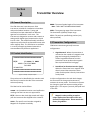
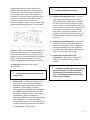
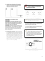
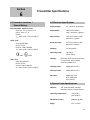
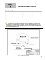
3902 Magnolia Rd.
Pearland, Texas 77584
Phone: 281-488-0788
Fax:
281-488-7080
E-mail: [email protected]
Website: www.isemagtech.com
LTM – Series
Models: LTM-250 and LTM-350
Magnetostrictive Level Transmitters
Instructions &
Operation Manual
LTM-350_IOM Rev.5 03/11
Table of Contents
Section 1: Warranty .......................................................................................................................................1
1.0 Warranty.......................................................................................................................................................... 1
Section 2: Transmitter Overview ...................................................................................................................2
2.0 General Description......................................................................................................................................... 2
2.1 Product Identification...................................................................................................................................... 2
2.2 Transmitter Configurations ............................................................................................................................. 2
2.3 Gage Mounted Transmitter............................................................................................................................. 3
2.4 Standalone Transmitter................................................................................................................................... 3
Section 3: Transmitter Description .................................................................................................................5
3.0 Detailed Description......................................................................................................................................... 5
3.1 Technology-Theory of Operation ..................................................................................................................... 5
Section 4: Installation.....................................................................................................................................7
4.0 Gage Mount Installation................................................................................................................................... 7
4.1 Standalone Installation..................................................................................................................................... 7
4.2 General Installation Guidelines ........................................................................................................................ 7
4.3 Insulation (against extreme heat/cold).......................................................................................................... 10
Section 5: Field Wiring..................................................................................................................................11
5.0 Recommended Loop Wiring........................................................................................................................... 11
5.1 Area Classification Installation Safety ............................................................................................................ 13
Section 6: Transmitter Specifications ...........................................................................................................14
6.0 Hazardous Locations/General Ratings ........................................................................................................... 14
6.1 Electrical Specifications .................................................................................................................................. 14
6.2 Sensor Probe Specifications ........................................................................................................................... 14
Section 7: Menu Structure and Features ......................................................................................................15
7.0 Pushbutton Operation................................................................................................................................... 15
7.1 Menu Structure ............................................................................................................................................. 16
7.2 Features (also exclusive features for models: LTM-250/350)....................................................................... 22
Table of Contents
Section 8: Transmitter Calibration and Troubleshooting................................................................................28
8.0 Calibration ..................................................................................................................................................... 28
8.1 Troubleshooting ............................................................................................................................................ 28
8.2 Power Supply Troubleshooting ..................................................................................................................... 29
8.3 General Troubleshooting............................................................................................................................... 29
Section 9: LTM-350 has HART Protocol .........................................................................................................30
9.0 HART Protocol: General Information / Flowchart of HART Menus............................................................... 30
Icon Key
Warning/Caution Valuable Operation Information
Important Information to Know
Read Carefully these Tips are the “DON’Ts” of the instrument.
Section
1
Warranty
1.0 Warranty
All Magtech products are warranted against defects
in materials and workmanship for a period of no
less than one year from the date of shipment. The
level gage chamber and process connections are
guaranteed for the life of the tank or vessel to
which it is attached. Floats are guaranteed for two
years. Magtech will repair or replace at its
discretion those products that fail to perform as
specified, with the following exceptions:
1. Products repaired or modified by persons
that are not authorized by Magtech.
2. Products subjected to misuse, negligence or
accidents.
3. Products that are connected, installed, or
otherwise used in such a way not in strict
accordance with manufacturer’s
instructions.
This warranty is in lieu of any other warranty
expressed or implied by any party other than
Magtech. Repairs and/or replacements shall be at
the sole discretion of Magtech based on the terms
and conditions of this warranty. Defective products
shall be returned to the factory prepaid by the
buyer after obtaining a Return Authorization
Number from Magtech. All warranty repairs or
replacements will be performed at the factory in
Pearland, Texas. Surface return freight will be paid
by Magtech. Factory warranties do not include field
service. Field service warranty repairs will be at the
buyer’s expense. Consult Magtech for field service
rates.
All Magtech gages and transmitters should
be unpacked and thoroughly inspected upon
receipt. Gages are shipped FOB factory and
are fully protected against damage or loss
during shipment. Any claims for parts
damaged during shipment should be
submitted within 15 days of receipt of goods
by customer.
We value your opinion and want to better
serve you. Please go our website:
www.isemagtech.com and click the customer
feedback survey option (on the left side of the
screen). Some of the best suggestions for
improvement come from our valued
customers. Let us know how we are doing and
what we can do better to improve your
satisfaction with our product and service.
Any modifications to terms and condition of this
warranty will not be binding unless made in writing
and signed by an authorized agent or official of
Magtech.
1
Section
2
Transmitter Overview
2.0 General Description
The LTM-Series are 2-wire electronic field
instruments, suitable for installation in hazardous
and non-hazardous locations. Testing and
certification has been obtained from different
agencies for installation in such areas. This
instrument is designed to measure and transmit an
analog and/or digital signal proportional to liquid
level in a tank. The complete assembly includes an
explosion-proof enclosure and attached sensor tube
and a magnetic float. The LTM-Series are available
in a variety of lengths and wetted materials to
accommodate many different applications.
2.1 Product Identification
wwwwwwwwwwwwwwwwwwwwwww
ZZ/ZZ
S/N AAAA / OL BBBB
MODEL LTM- 350-G-XXXX
TAG YYYY
ISE-MAGTECH
wwwwwwwwwwwwwwwwwwwwwww
wwwwwwwwwwwwwwwwwwwwwww
Figure 1. Example label/name plate
The product can be identified by the stainless steel
label that is located on the side of the transmitter
enclosure/housing.
The label can be read as follows:
wwww = Any hazardous location area classification
markings that the instrument is approved for.
ZZ/ZZ = Born on date; the2 digit month and 2 digit
year the instrument was shipped to the customer.
AAAA = The specific serial number assigned by
Magtech for complete traceability.
BBBB = The overall probe length of the instrument.
Note: THIS IS NOT THE MEASURING RANGE.
XXXX = The measuring range of the instrument.
The 0 and 100% (4/20mA) output range.
YYYY = The end user specified tag number (only
when specified).
2.2 Transmitter Configurations
LTM-Series transmitters generally have two
configurations:
1. Gage Mounted: Where the transmitter is
mounted on the outside of a magnetic level
gage and strategically located within a
certain longitudinal distance from the
transmitter sensor probe and a magnetic
float is placed inside the level gage.
2. Standalone (or Direction Insertion Type):
Where the transmitter has a magnetic float
directly around the transmitter sensor
probe and the probe is directly inserted into
a tank/vessel.
In either configuration as the tank level changes,
the float tracks the change and continuously
activates the sensor probe. The electronics process
the change in signal and output an analog and/or
digital signal. This output is precisely the liquid level
in the tank.
Magtech is always willing to explore
unique applications that require their own
distinctive configurations. Please consult the
factory for guidance.
2
2.3 Gage Mounted Transmitter
2.4 Standalone Transmitter
The LTM-Series may be strapped to the outside of
the Magtech LG series magnetic level gage. In such
an installation, it is used as an accessory transmitter
for the visual level gage. The same float used to
activate the magnetic gage is also used to activate
the magnetostrictive sensor of the LTM and
transmit a directly proportional 4/20mA signal.
When a magnetic level gage is not present, the LTM
can be inserted into the tank/vessel with its own
float mounted around the sensor tube.
The depictions below show the standalone version
of the LTM-Series with various process connections
and the standard float stop with centering ring.
The depiction below shows the gage mount
installation of the LTM-Series to a mag-gage. The
transmitters may be calibrated for the same range
as the visual indicator on the mag-gage, or for part
of the range depending on the application.
Figure 3. Transmitters with various process connections.
In Figure 3:
Transmitter A depicts a standard ¾” compression
fitting that is on all standalone transmitters.
Transmitter B depicts a ¾” compression fitting and
a hex plug. This option is highly recommended
because the hex plug is selected based on the
float’s diameter (OD), so if the instrument ever
needs to be removed or serviced for any reason it
can be removed by the hex plug.
Transmitter C depicts a flanged option with a ¾”
compression fitting and a hex plug.
Figure 2. Gage mounted transmitter
Magtech transmitters may also be used in
conjunction with other manufacturers’
magnetic level gages. Full warranties will apply
upon factory approval. Float and or Indicator
replacement may be required.
3
A stilling well may be used along with the
transmitter inside the tank. Stilling-well is a pipe
external to the sensor probe and float encasing the
entire assembly protecting it from surface agitation
or from physical damage due to the length of the
sensor probe. A depiction of a transmitter with a
stilling well is provided below.
Optional Features that are available with the
LTM-350 but NOT the LTM-250 are:
1. HART Protocol, which enables:
a. A second digital output proportional to
an interface level (requires a second
float of different specific gravity)
b. A digital temperature output that
reflects the liquid temperature.
c. Advanced diagnostics and features
highly beneficial for commissioning,
troubleshooting or monitoring.
Up to two floats may be used with the LTM-350
only. The second float will typically sense the
interface level (the heavier of the two fluids) in the
tank. The specific gravity of the second float will be
such that it can be totally immersed in the lighter
fluid. The drawing below shows a transmitter with
dual floats, one for total level and the other for
interface level (also available with various process
connections).
Figure 4. Transmitter with a Stilling-well
When a stilling well is used, care should be
exercised when installing the tube to center it in
the chamber so that the float can freely travel
the entire length of the probe. Stilling wells are
required for transmitters over 10 feet or the
instrument cannot be considered under
warranty.
Figure 5. Dual Output Transmitter
A dual output transmitter is also available
in a gage mount configuration. Consult factory
for further details.
4
Section
3
Transmitter Description
3.0 Detailed Description
The LTM-Series is an assembly of two major
components:
The Sensor Tube Assembly: This is a 5/8” diameter
stainless steel probe, sealed on one end, with the
magnetostrictive waveguide in its center. In
addition to the magnetostrictive waveguide, the
tube also houses the optional temperature sensor
and the sensing elements. The tube is made to
lengths of 2-30ft. in rigid construction.
The Enclosure and Electronics: The extruded
aluminum housing has two compartments. The
enclosure is rated NEMA 4X and 7. One side
contains the microprocessor board assembly and
calibration push buttons. The other side contains
the field wiring termination board. The electronics
module is connected to the detector board of the
sensor tube assembly via a plug-in cable. The
electronics module houses printed circuit boards
(PCB) that encompass surface mount component
construction utilizing the latest integrated circuit
technology.
Magtech also has a stainless steel enclosure
that can be utilized. Please contact factory for
further details.
3.1 Technology – Theory of Operation
The LTM-250/350 series level transmitters are
based on the principle of magnetostriction, first
used for digital delay lines and later precision
distance or displacement in the machine tool
industry. This principle, if designed and applied
properly, has potentially very high measurement
resolution, typically better than 0.001 inch. In the
machine tool industry such a high resolution is
desirable. In the level measurement application,
however, a resolution of 0.03 inch is more than
adequate.
In a brief description, the magnetostrictive principle
consists of a wire extruded and heat treated under
carefully chosen conditions to retain desired
magnetic properties, which is pulsed by a circuit
with a relatively high current pulse. The high
current pulse produces a circular magnetic field as it
travels down the wire at the speed of sound.
Another magnetic field generated by a permanent
magnet (the float), placed near or around the wire
at some distance from the point of entry of this
pulse interferes with the magnetic field of the
current pulse and a torsional force results at the
collision point.
Figure 6. Principle of Operation
The effect of this torsion force is a twist to the wire
at this point producing torsion wave traveling
towards both ends of the wire. The propagation
time (or time-of-flight) of this wave is measured
precisely and if the wire properties remain stable, it
is very repeatable at about 5-10 microseconds per
inch, which is approximately the speed of sound in
that medium. By measuring the exact number of
microseconds it took the torsion wave to reach a
designated termination point of the wire, the
distance to the magnet from this termination point
can be easily calculated.
5
A high-speed microcontroller is utilized in the
design to process and calculate the elapsed time
measurement. Accurate crystals are used for the
time based to resolve sub-microsecond timing
increments. The binary number, equivalent to the
microseconds of the echo travel time is used to
calculate the distance of the float and a
corresponding digital signal is output. A basic block
diagram describing the operation is shown below.
Figure 7. Basic Transmitter Block Diagram
Calibration routines are included in the software to
the 0% and 100% points for any distance desired.
Even reverse calibration is a simple task using the
software routines. Reverse calibration is desirable if
ullage instead of level is required, or when the
probe is installed with bottom mount electronics.
The LTM-350 transmitter has four output
configurations.
Configuration options must be chosen at
quoting stage.
LTM-350, via HART protocol only.
2. Primary Level and Interface Level – A second
float may be added below the first, and the
second output will be calibrated automatically.
The second time interval is timed in the same
manner as the first one and added to the first to
derive the position of the heavier float. The two
floats require a separation of approximately
three inches. The float size, geometry, and
magnetic strength all play a factor in how close
the two floats can be without interfering with
each other.
3. Primary Level and Temperature – An optional
temperature sensor is embedded inside the
bottom tip of the probe, and it is configured to
be the third digital output of the transmitter,
and comes factory calibrated for the operating
range of -50C to 149C (-58F to 300F)
4. Primary Level, Interface Level, and
Temperature – This options is called a ‘fullblown” unit and offers all three possible
outputs.
A deadband of approximately three inches,
next to the detector, is fixed in the software
and the float is not permitted to enter this
area. If this happens output readings maybe
erratic or go to fail mode.
1. Primary Level – The most basic version of this
transmitter is that it computes the distance
between the float and the detector from the
elapsed time measurement. A specific
interrogation pulse is applied to the waveguide.
Any feedback signal received before and after
this window is rejected as noise. Even signals
received during the active window are
evaluated and filtered so that only high integrity
data is accepted. The conditioned signal is
converted to a percent of full-scale number and
a number representing the distance and output
as a digital signal. (LTM-250/350)
6
Section
4
Installation
4.0 Gage Mount Installation
The LTM-Series can be mounted to the side of a
Magtech LG series level gage using special mounting
brackets and stainless steel hose clamps. When
mounting the transmitter to an LG series gage the
active sensor region of the probe should fall within
the centerline of the process connections on the
gage. If the transmitter’s deadband region is inside
the centerline of the process connections the
transmitter will not output an accurate
measurement because the active region of the
probe is too short. When placing an order for a
transmitter to accompany an existing gage it is
important to indicate the style of the gage, the
temperature, and the center-to-center dimension.
Calibration of the probe is factory set to the
center-to-center dimensions provided; however a
re-ranging may have to be performed to match the
probe to the desired control room specifications.
See Section 7.1 “Change Range” for more details.
4.1 Standalone Installation
The LTM-Series standalone transmitter comes
equipped with a ¾” mnpt compression fitting,
mounted approximately 3 to 6 inches below the
electronics housing. The fitting is placed in this area
to ensure the transmitter is calibrated in the sensor
tubes active region. Refer to the standalone
drawings for a visual description of the transmitter
features. Optional configurations are available
upon request (2” mnpt, flanges, etc…). The
magnetic float used in the stand-alone unit is
designed to travel up the sensor tube with the
change in fluid level. If build-up of process or
contaminates should restrict the movement of the
float, the transmitter sensor tube will have to be
cleaned or the float may have to be replaced with
one that has a larger inside diameter. The floats are
designed to match the pressure and specific gravity
for the process being measured and come in various
materials ranging from stainless to kynar. The
magnetic float can be changed out at any time to
accommodate the processes being measured. The
float stop, located at the bottom of the
transmitters, can be removed to allow the float to
slide off the sensor tube.
4.2 General Installation Guidelines
The basic steps to installing the LTMs are:
1. Inspection of equipment: Inspect the parts
that are listed on the packing slip. Make sure
nothing appears to be damaged such as a
broken glass from the level indicator assembly
(flippers), damaged float, or a damaged
transmitter. Please file a claim with the
shipping company immediately if it is believed
the shipment has arrived damaged and be
prepared to provide pictures.
The sensor probe of the transmitter
SHOULD NOT BE BENT, BOWED, OR KINKED in
any way or the transmitter will not work (will
most likely go into fail mode).
The following is a depiction of damaged probes:
Figure 8. All damaged sensor probes
7
2. Identify Proper Orientation of Transmitter:
There are a few possible orientations of the
LTM Series transmitters, they are:
Do not over tighten the clamps because
they will bend and distort.
Figure 10. Top view of mounting clamps and sensor probe
Figure 9. Possible transmitter configurations
Transmitter A is a standard top mount
configuration.
Transmitter B is a top mount with elbow, usually
utilized when there are temperature or head room
issues. There is also a bottom mount with elbow
configuration which is not depicted.
Transmitter C is a bottom mount transmitter with
remote electronics. This configuration is utilized in
more extreme temperatures or for accessibility.
There is also top mount with remote electronics
which is not depicted.
3. Mounting the Transmitter. Align the 4/20 mA
(or 0 and 100%) markings with the center of the
top and bottom process connection. Mount the
transmitter along the level gage and use a nut
driver to tighten the clamps so the sensor probe
of the transmitter is held securely (will not slip
up and down). Keep the transmitter supported
while the clamps are being tightened (this can
require more than one person).
A: Is the correct way to have clamps tightened.
The clamps do not have to meet.
B: Is incorrect because the clamp is flipped around
and will not grip the sensor probe.
C: Is incorrect because the clamp has been tighten
too much and damaged/distorted.
Effects of high vibration can be minimized
early on by notifying the factory at time of
order. The electronics can be remote mounted
and special insulators can be installed. Please
see the depiction below.
Figure 11. Insulator for high vibration
8
4. Remote Mount Electronics Option. Due to
process temperature, vibration or accessibility
the housing/electronics of the LTM transmitter
can be remote mounted as far as 25 ft. The
housing/electronics are supplied with a pipemount bracket that can be mounted most
nearby posts or pipes with hose clamps. The
drawing below depicts a gage mounted
transmitter in the top mount remote electronics
configuration.
There are a variety of ways to install a
standalone transmitters (i.e. crane, lift, etc…),
the basic rule to remember when installing an
LTM transmitter is DO NOT DAMAGE the
sensor probe, this will void the warranty. If
damage is suspected please contact the factory
and be prepared to provide pictures.
In REMOTE MOUNT electronic options
please support the sensor probe at the
elbow/condulet and then every 3 feet
(depending on length of cable). Support at
every 2 feet may be required if explosion proof
conduit is utilized by the end user.
Figure 12. Gage mount transmitter in the top mount remote
electronics configuration.
NEVER install the sensor probe inside an
insulation blanket that may be around the
level gage. This will overheat the sensor probe
and cause failure.
NEVER bend, bow or cause a kink in the
sensor probe, this will damage the instrument
and void the warranty. Do not attempt to
straighten the sensor probe, this will not help
the instrument work. If the shipment arrives
damaged please file a claim with the shipping
company and contact the factory to arrange for
a replacement.
9
4.3 Insulation (against extreme heat/cold)
Magtech strongly recommends that an experienced
Magtech Technician do insulation of the magnetic
level gages at the factory with externally mounted
transmitters.
If Cryogenic “Hard Skin” cold service type
insulation is required, it must be done at the
factory due to the custom “TUBE in TUBE”
design necessary for removal of the
transmitter if needed.
(When insulating gages):
Magtech level transmitters have a maximum
operating temperature of 300 F. When insulating a
mag-gage and transmitter assembly in HOT service,
keep the transmitter OUTSIDE the insulating
material. Special blankets for this type of insulation
are available from Magtech, and recommended to
guarantee proper insulation. For further
information consult the factory.
If insulation is going to be done in the field, then the
following guidelines MUST be followed:
1. Flexible type insulation jackets (NOT HARD
SKIN) are required and must be installed around
the mag-gage chamber only. DO NOT cover the
LTM sensor tube, as this may burn up the
sensor and possibly the electronics.
2. After the insulation jacket is installed, the LTM
sensor tube must be remounted at its factorypreset distance from the mag-gage chamber
and must be parallel to the chamber as well
(small cut-outs in the jacket are required to reattach the transmitter properly).
3. Make sure that the 0% and 100% (4/20mA)
marking on the sensor tube are re-aligned at
the centers of the process connections.
10
Section
5
Field Wiring
5.0 Recommended Loop Wiring
The following is the recommended loop wiring.
Figure 13. Recommended Loop Wiring
11
The following is the Hart Topology.
Figure 14. HART Loop Topology
Please visit www.hartcomm2.org to learn more about HART Protocol.
12
5.1 Area Classification Installation Safety
If the instrument is used as an explosion proof (exp) device then exp conduit must be sealed within 18
inches of the termination point – at the instrument.
Power must be supplied by an isolated supply.
Caution-To reduce the risk of ignition of hazardous atmospheres, disconnect the device from the supply
circuit, or area must be known to be non-hazardous, before opening.
13
Section
Transmitter Specifications
6
6.1 Hazardous Locations /
General Ratings
CSA and CSAUS: Explosion Proof:
Class I Div. 1 or 2, Grps. B, C, D
Class II, Grps. E, F, G
Class III
Tamb -40°C to 85°C (-40°F to 185°F)
ATEX: Ex d:
Sira 10ATEX1308X
Ex d IIC T5 Gb
Ex tb IIIC T100°C IP66 Db
Tamb -40°C to 85°C (-40°F to 185°F)
0344
6.2 Electronic Specifications
Supply Voltage:
13 – 36 Vdc (13V @ 20mA)
Repeatability:
.005% of full scale or
.010”, whichever is greater
Non-Linearity:
.01% of full scale or .030”,
whichever is greater
Sensor Accuracy:
.01% of full scale or .030”,
whichever is greater
Damping:
1 to 26 seconds
Operating Temp:
-50 to 85 C
(-58 to 185 F)
II 2GD
IECEx: Ex d:
IECEx SIR 10.0150X
Ex d IIC T5 Gb
Ex tb IIC T100°C IP66 Db
Tamb -40°C to 85°C (-40°F to 185°F)
Housing:
Explosion proof, dual compartment,
½”npt conduit, epoxy coated
aluminum; NEMA 4X, 7
Humidity Limits:
SAMA PMC 31.1-5.2
Vibration Limits:
SAMA PMC 31.1-5.3
RFI Limits:
SAMA PMC 31.120 to 1000 MHz
Up to 30 V/m
6.3 Sensor Probe Specifications
Material:
5/8” 316ss standard, optional:
Hastalloy, Monel, or Kynar sleeved
Operating Temperature:
-50 to 149 C
(-58 to 300 F)
Maximum Pressure:
2000psig @ 300F
Range:
12 in. to 30 ft.
14
Section
7
Menu Structure and Features
7.0 Pushbutton Operation
The menu structure and pushbutton operation of the LTM series transmitters is simple and user-friendly. The
electronics module has 3 pushbuttons (from left to right):
↑ : This button is used to increment values and change “Yes” to “No” and “No” to “Yes”.
↓ : This button is used to decrement values and change “Yes” to “No” and “No” to “Yes”.
← : This is the enter button used to execute functions and enter/exit into or out of submenus.
The pushbuttons are timed not pressurized. It does not matter how hard/firm you press them. The
buttons depend on the length of time they are pressed. The longer you hold the button the faster it will
increment/decrement values. Hold the enter button down for 2 seconds to enter the configuration menus
and 1 second for all subsequent menus.
2 pins on the left
2 pins on the right
Figure 15. Front Panel of Electronics Module
15
7.1 Menu Structure
Main Screen (scrolling):
The menu structure has been designed so the end user can make parameter changes relatively fast and easy.
Below is a detailed description of these menus.
The LTM-250/350 LCD is a 2x8 character screen. The main screen scrolls between the following parameters:
1.
2.
3.
4.
5.
Level (in selected engineering units)
Interface (when option is provided – in selected engineering units)-LTM-350 only
Temperature (when option is provided – in selected engineering units)-LTM-350 only
The analog current corresponding to level (in mA)
Percent of range corresponding to level (in %)
If the user desires to enter into the configuration menus simply press/hold the enter button for 2 seconds.
Make sure the electronics are not in write protect mode.
The menu order can change and new menus can be introduced based on transmitter output options and
hardware or software revisions.
16
The following is the LTM-250/350 LCD Menu Flowchart
Magtech
LTM-250
or
Magtech
LTM-350
SW Rev
1.00.00
HW Rev
1.00.00
Display?
Scroll
> Level
> Intrface* > Temp** > mA Out > % Range
SelLngth
30.00 in
Lvl Unit
in > ft > mm > cm > m
Temp Unit**
C > F >R > K
Sel PV*
Level > Interface
Sel Alrm
FailHigh > FailLow > HoldOut
ChgRnge? >>>
Yes > No (yes)
Sel LRV >>> Sel URV
0.00 in
24.00 in
SelDamp
1 sec
ROC Fltr
10.0in/s
TrmSnsr? >>>
Yes > No (yes)
TrimZero >>>
TrimZero >>>
-Busy-
TrimSpan >>>
24.00in
TrimSpan >>>
-Busy-
Span
Error (if incorrect)
Offset
0.00in
TrimDAC? >>>
Yes > No (yes)
Trim 4mA >>>
Trim20mA
120
3860
TstLoop? >>> LoopTest
Yes > No (yes) 4.00 mA
Exit?
Yes > No
*
**
Only applies when Interface Float is included
Only applies when Temperature Sensor is included
17
7.1 Menu Structure Continued…
Description
Manufacturer and Model:
Software Revision Status:
This is the current software revision.
Hardware Revision Status:
This is the current hardware revision.
Scrolling Option:
Allows the user to stop the main menu from
scrolling and choose 1 of 5 possible parameters:
Engineering Units (level, interface, and temp),
Current (mA), or Percentage. Select the desired
parameter and then press enter. “Scroll” is the
default parameter this option keep the main menu
scrolling. See section “7.2 Features” for more
details.
LCD Menu (example)
M
L
a
T
g
M
t
-
S W
R
1 . 0
e
3
c
5
h
0
e v
0 . 0
0
H W
R e v
1 . 0 0 . 0 0
D
i
s
S
p
c
l
r
a
o
y
l
?
l
S
e
3
l
0
L
.
n
0
g
0
t
i
h
n
L
v
l
U
n
i
t
i
s
n
T e m p U n i
t
C
Interface and Temperature options only
appear if the option(s) are configured.
Select Length:
Note: THIS IS NOT THE MEASURING RANGE.
This parameter should only reflect the overall
sensor length. It can be adjusted by incrementing
and decrementing the value and then pressing
enter.
Level Units:
This menu can be used to change the level
engineering units. It can be changed by
incrementing/decrementing to one of the following
units: in, ft, mm, cm, m and then pressing enter.
Temperature Units:
This menu can be used to change the temperature
engineering units.
It can be changed by
incrementing/decrementing to one of the following
units: F, C, R, K and then pressing enter.
o
This menu only appears if the temperature
option is provided.
18
7.1 Menu Structure Continued…
Description
Select PV:
This menu allows the user to select the
measurement that controls the transmitter’s
current output (mA).
LCD Menu (examples)
S e l
P V
L e v e l
This menu only appears if the interface
(2 floats) option is provided.
Select Alarm:
The following alarm settings can be chosen:
“FailHigh” = 21.00mA
“FailLow” = 3.50mA
“HoldOut” = holds last good reading until
transmitter recovers.
S e l A l a r m
F a i l H i g h
Change Range:
This menu allows the user to change the measuring
range or span. Enter the menu by changing the
“No” to a “Yes” and press enter.
C h g R n g e ?
N o
- Select Lower Range Value (LRV):
This is the 4.00mA (0.00%) point on the senor. This
value should only be incremented. For example if
the value is changed from “0.00in” to “3.00in” the
4.00mA point will shift 3.00 inches higher than the
original point. It is recommended to leave this at
0.00 most of the time unless a special circumstance
arises. Press enter to go the next screen.
S e l
L R V
0 . 0 0 i n
- Select Upper Range Value (URV):
This is the 20.00mA (100.00%) point on the sensor.
This value should only be decremented. Changing
this parameter will change the measuring range or
span of the transmitter.
S e l
U R V
2 0 . 0 0 i n
Select Damping:
This parameter is used to slow down the reaction of
the instrument in order to ignore or average out
any agitation on the process surface that may be
causing an unsteady output. The units are fixed in
seconds and values can be from 1 to 26 seconds.
S e l
D a m p
1
s
19
7.1 Menu Structure Continued…
Description
LCD Menus (examples)
Rate of Change (RoC) Filter:
This parameter helps ignore erroneous readings
from the transmitter’s surroundings. If the user
knows how fast the level can change in the vessel
(i.e. inches per second) then this parameter should
be set at a rate that the level in the vessel cannot
suddenly jump to. See section “7.2 Features” for
more details.
R o C F l t r
1 0 .0 i n / s
Trim Sensor:
This menu can be used to recalibrate the
transmitter.
T r m S n s r ?
N o
There is no need to recalibrate the
instrument simply use the “Change Range”
menu and change the LRV and URV as desired.
If the need arises to use this menu then
level simulation will be required at 0 and 100
percent.
Offset:
This parameter simply adds a digital value to the
measuring range or span it does NOT shift or move
the measuring range. See section “7.2 Features” for
more details.
O f f s e t
0 . 0 0 i n
The span will not change and the 4/20mA
will not shift from its original calibrated points.
This value also affects the reading for interface
level when available.
20
7.1 Menu Structure Continued…
Description
Trim Digital-Analog-Converter (DAC):
These are factory set parameters used to provide an
accurate 4.000mA and 20.000mA. This parameter
should not be changed as Magtech uses NIST
traceable equipment to calibrate our transmitters
and only accredited laboratories for the annual
calibration of our equipment. This menu will allow
the user to change the accuracy of the transmitter
output.
LCD Menu (examples)
T r i m D A C ?
N o
A current meter should be used to monitor
the 4/20mA when this function is selected.
Test Loop:
This function allows for direct control of the
Transmitter’s current output (mA) capability.
Simply enter into this menu and change the current
(mA) output as desired. This option is excellent for
plant startup verification.
T s t L o o p ?
N o
Exit:
This signifies the last menu before the main screen.
If the user desires go back through the
configuration menus then change the “Yes” to “No”
and review the configuration again else press enter
while the screen shows “Yes” and return to the
main screen.
E x i t ?
Y e s
21
7.2 Features
This section will describe in more detail some of the LCD Menus and new features exclusive to models
LTM-250/350.
Scrolling Option: When choosing not to scroll the main menu the following options can be chosen by pressing
the up and down push buttons (exclusively for models LTM-250/350).
1. Display?
Scroll (or)
Display?
Level (or)
Display?
Display?
Intrface (or) Temp (or)
Display?
Display?
mA Out (or) % Range
The “Scroll” option will vary depending on how many outputs are configured.
Rate of Change (RoC) Filter: The RoC filter is a continuous monitor of how fast (the rate) the level is rising
and falling. It is also an excellent tool to help eliminate any temporary spontaneous noise that may be present
in-field. For example if the level in a tank cannot rise or fall faster than 30.0 in/s then the setting for the RoC
filter should be set to 15.0 in/s or less to help filter/ignore erroneous readings. Note: The engineering units will
change according to units selected (i.e. cm/s) – (exclusively for models LTM-250/350).
Offset: The offset is a digital number that gets added to both the LRV and URV to account for any distance
below the sensor probes measuring distance. For example if the offset is changed from “0.00in” to “2.00in” the
‘Level’ on the main screen will show “2.00in” at 4.00mA and the 20.00mA value will simply have 2.00 inches
added to it.
The span will not change and the 4/20mA will not shift from its original calibrated points. This offset
value will also add to the interface level when available.
22
7.2 Features (Exclusive to the LTM-250/350 models)
There is an “advance” menu incorporated into the LTM-250/350 models. To access this menu press and
hold the increment (↑) button first then while holding the increment button press and hold the enter
button for 3 seconds. A new menu will appear on the LCD screen.
The following is a flow chart of the “advanced” menus
ComPort? >>>
Yes > No (yes)
v
Default? >>>
Yes > No (yes)
Serial
Active
Default?
Load >Save
>>>
Select >>>>>>>>>>>>>>>>>>>>>>>>>>>>>>
(Load) Factory > Sensor1 > Sensor2 > Sensor 3
Defaults
Loaded
>>>
Select >>>>>>>>>>>>>>>>>>>>>>>>>>>>>>
(Save) Sensor1 > Sensor2 > Sensor3
Defaults
Saved
v
Deadzone
1.50in
v
1pt Cal? >>> SelLngth >>> Sel LRV >>> Sel URV >>> Energy >>> DCOffset >>> HoldTime >>> CrntLvl? >>> CrntLvl?
Yes > No (yes) 30.00in
0.00in
24.00in
22%
1.50V
4 us
0.00in
v
LvlAdjst >>> CrntLvl? >>> CrntLvl?
Yes > No (yes) 0.00in
-Busyv
FlipPrb? >>> Config >>>
ReRange? >>> Sel LRV >>> Sel URV >>> CrntLvl? >>> CrntLvl?
Yes > No (yes) Bottom > Top Yes>No (yes) 0.00in
24.00in
0.00in
-Busyv
ChgSgnl? >>> Energy >>>
Yes > No (yes)
22%
v
PW Filter >>> PW Min >>>
On>Off (On) 40 tics
v
Exit?
Yes > No
-Busy-
(no) >>>>>>>>>>>>>>>>>>>> ^
DCOffset >>> HoldTime
1.50V
4 us
PW Max
100 tics
23
7.2 Features (Exclusive to the LTM-250/350 models)
This section describes the “advance” menus in detail.
ComPort: This menu is currently only utilized at the factory and will not assist in any troubleshooting. When
the menu first appears the “No” option is defaulted, simply press enter to bypass this option. If “Yes” is selected
and this menu is accidently entered into then the push buttons will be locked out. Simply cycle the power to the
instrument to clear the effect of entering into this option.
Default: The next menu is the “Default Configurations” menu. This option allows the user to “load” the original
factory settings or load settings saved in slots labeled “Sensor 1”, “Sensor 2” or “Sensor 3” (if utilized by end
user). If desired one electronics module can save settings for 3 other sensor probes by calibrating the
electronics module to a particular sensor probe then saving those settings into slots labeled sensor 1, 2, or 3.
Change the menu screen from “load” to “save”. Then the user can save current setting into slots labeled sensor
1, 2 or 3 and load from these slots as desired.
-
Loading Factory Defaults: Enter into the “Defaults” menu by changing the “no” to a “yes”. Then the
option to “Load” will appear. Press enter and the “Factory” option will appear then press enter on more
time to execute the load from defaults (settings can also be loaded from Sensor 1, 2, or 3 by using the
up or down arrows on the “Factory” screen if the user has utilized the other slots).
-
Saving Settings: Enter into the “Defaults” menu by changing the “no” to a “yes”. Then the option to
“Load” will appear. Use the up or down arrow to change the “Load” to “Save” option. Press enter and
the next menu will appear with “Sensor 1”. By pressing enter the current settings of the transmitter will
be saved. At the “Sensor 1” menu screen if the up or down arrow is pressed the user has the option to
save the transmitter settings into “Sensor 2” or “Sensor 3” slots. Note: One electronics module can
potentially hold up to 3 other transmitter settings.
The factory settings can never be overwritten (or saved to), only loaded from.
Deadzone: This menu is mainly utilized at the factory to achieve optimal linearity near the deadband
close to the electronics. This feature was released just in case in-field adjustments are necessary.
This option/feature only appears in software revisions 1.01.15 or higher.
24
7.2 Features (Exclusive to the LTM-250/350 models)
Please consult factory before attempting this procedure. Document transmitter’s serial number for
better assistance.
1-point Calibration Procedure (1pt Cal): The following menu is the 1 –point Calibration procedure.
This procedure was designed to help the user get up and running in an emergency. If electronics have to be
shared in an emergency the following procedure guides the user through a “quick” calibration procedure that
does not require level simulation but instead works with the current level (1 point) in the vessel/tank.
1. Enter into the “1pt Cal” menu by changing the “no” to a “yes” and pressing enter.
2. The first menu is “SelLngth” or select length. This is not the measuring range but the overall probe
length. This information can be found on the label of the instrument housing. (See Section 2.1 Product
Identification). Enter the value in using the up or down arrows and press enter.
3. The second menu is “Sel LRV” or select lower range value. Most of the time this value is at 0.00in. It is
recommended to leave this value at zero and press enter.
4. The next menu is “Sel URV” or select upper range value. Enter in the desired measuring range and press
enter.
5. The “Energy” menu is next. This parameter controls the amount of energy being sent down the sensor
probe. Longer sensor probes require more energy shorter sensor probes require less energy. Please
contact the factory for guidance with this parameter.
6. The “DCOffset” menu is the signal to noise ration. Please contact the factory for guidance with this
parameter.
7. The “HoldTime” menu is the amount of time the energy being sent down the probe is sustained. Note:
a longer hold time can increase the deadband near the electronics. Please contact the factory for
guidance with this parameter.
8. The last menu is the “CrntLvl” or current level menu. Enter the known current level in the vessel/tank
(in engineering units) and press enter. The calibration should take place and the transmitter should be
operational. If the next menu appears then the operation was successful. If the menu reverts back to
the beginning of the “1pt Cal” menu then the operation was unsuccessful. Further troubleshooting may
be necessary if the operation is unsuccessful. See Section 8 for troubleshooting guide.
The 1-point calibration may not be within the published accuracy specification. Again this procedure
was designed to get a critical application up and running. A recalibration (two point calibration) may be
highly desirable as soon as the opportunity presents itself.
Level Adjustment (LvlAdjst): If the level gage indicator and level transmitter reading do not match or appear
to be incorrect by a few inches then the “LvlAdjst” function can be utilized. Enter into the menu and simply use
the up and down push buttons to enter the current level being displayed by the level gages visual indicator and
then press enter. The transmitter will adjust the calibration and output accordingly. Note: Be careful make sure
this is what is desired.
25
7.2 Features (Exclusive to the LTM-250/350 models)
Field Reversible Transmitter (FlipPrb): An important and key feature of the LTM-250 and LTM-350 Models is
the ability to flip (rotate) the entire transmitter 180 degrees. This procedure is only for gage mount
transmitters with an elbow connection on them. If the transmitter does not have an elbow connection please
contact factory for assistance. If the need arises and a bottom mount transmitter is preferred over a top mount
transmitter or vice versa then following these simple steps. THIS PROCEDURE IS FOR GAGE MOUNT
TRANSMITTERS ONLY.
1. Physically flip (rotate) the entire transmitter (this includes the sensor probe) and mount it accordingly.
Be careful not to damage the sensor probe while rotating the transmitter.
2. Remove the front glass cover of the transmitter enclosure and then using needle nose pliers pull on the
protection screws (snake-eye screws) to pull out the electronics module. Alternate pulling on the screws
in order to prevent damage to the electronics module.
3. Rotate the electronics 180 degrees module and insert it back into the enclosure. The module should
now be right side up.
Do not twist or rotate the transmitter housing to adjust the conduit entry. The conduit entry must be
left in the opposite position.
4. There is a “special” configuration menu that is utilized to achieve this task. To access this menu press
and hold the increment (↑) button then while holding the increment button press and hold the enter
button for 3 seconds.
5. The “FlipPrb?” (Flip Probe) menu should appear. Use the up or down buttons to select “Yes” if rotating
the sensor is what is desired else select no and exit the menu.
6. When “Yes” is selected the next menu is the “Config” (Configuration/Orientation) menu. This is where
the “Top” or “Bottom” mount configuration is selected. This configuration/orientation is with reference
to where the sensor probe “bulkhead” is located on top or bottom. Select the appropriate “Config” and
press enter. If the original orientation is selection the menu will revert back to “FlipPrb?” menu.
7. The next menu is “Rerange?” (Change Range) menu. Select “Yes” if the measuring range (or span) is
changing from the original span. Select “No” if the span is to able to remain the same. Selecting “Yes”
will then go through change range procedure discussed in section 7.1 of this manual.
8. After the “Rerange?” menu is the “CrntLvl?” (current level) menu. Simply enter where the existing level
is in the vessel and a one-point calibration will take place automatically and the next menu will appear.
If the next menu appears then the operation was successful. If the menu reverts back to the beginning
of the “FlipPrb” menu then the operation was unsuccessful. Further troubleshooting may be necessary
if the operation is unsuccessful. See Section 8 for troubleshooting guide.
26
7.2 Features (Exclusive to the LTM-250/350 models)
Change Signal (ChngSgnl): The next and final menu in the special features menu is “ChngSgnl” or change
signal option. The feature allows the adjustment of the signal being sent down the sensor probe. It can be
utilized when one electronics module is being utilized to save settings for various different length sensor probes.
This menu has 3 parameters that can be adjusted. The first is “Energy” [%], it is increased for a longer sensor
probe and decreased for a shorter sensor probe. The second parameter is “DCOffset” or DC Offset [v], this
parameter is decreased for longer sensor probes and increased for shorter sensor probes. The third (and final)
parameter is the “HoldTime” or hold time [us], this parameter recommended to stay within a certain range.
There is purposely not much detail on this option as it is recommended that these parameters not be
changed unless the electronics module is being utilized for more than one sensor probe. It is also
recommended that the user be guided by the factory if this option is being utilized.
This option is also intended for mainly factory use. Changing these parameters can cause undesirable
results. Please consult factory with any questions. The “factory” default configurations can be loaded if the
parameters have been drastically changed.
Pulse Width Filter (PW Filtr): The pulse width filter can be utilized for dual output (level and interface)
applications if there are any erroneous readings being transmitted or displayed. This feature can be adjusted so
the unique signal from the magnetic float can be concentrated on and all other false signals are ignored.
This option/feature only appears in software revisions 1.01.15 or higher.
Conversion from Gage Mount to Standalone: When converting from a gage mount transmitter to a
standalone transmitter or vice versa simply contact the factory to order appropriate parts. Please have the
serial number of the transmitter documented so the factory can make traceable record changes and offer better
assistance. Most conversions can now be done in-field with minor configurations and calibration.
Converting from gage mount to standalone: Remove the transmitter from the gage, then remove
4/20mA (or 0/100%) stickers from the sensor probe. Call factory with serial number and desired process
connections (3/4”mnpt, 2”mnpt hex plug, flanges, etc…).
Converting from standalone to gage mount: Remove the transmitter from the vessel, then remove
process connections and float. Call factory with serial number of transmitter and the level gage to which
the transmitter is to be mounted.
Always be careful not to damage the sensor probe when removing/installing the transmitter to/from the
gage or vessel.
27
Section
8
Transmitter Calibration and
LTM Troubleshooting
8.0 Calibration
There really is no need to re-calibrate this
instrument. The LTM-Series arrive calibrated
to specified measuring ranges at order
placement.
If the need arises and a recalibration is deemed
necessary please follow these instructions carefully.
Level simulation will be required at 0% and
100% positions.
1. Verify the “probe length” is not the same as
the” measuring range” desired. If so please
change accordingly.
See Sections 2.1 and 7.1.
2. Go to the “Change Range” menu and set
the desired URV (measuring range).
3. Go to the “Trim Sensor” menu and enter.
4. At the “Trim Zero” screen place the level (or
magnet/float) at 0% (4mA point) and then
press enter.
5. At the “Trim Span” screen place the level
(or magnet/float) at 100% (20mA point) and
then press enter.
6. “Exit” the configuration menus and the
instrument should be calibrated. If not
begin to troubleshoot or consult factory for
assistance.
Error Preventative Calibration: The LTM-250/350
transmitters are protected from incorrect
calibration so if something is done incorrectly it will
display “Span Error” on the LCD for 5 seconds and
then return to the beginning of the “Trim Sensor”
menu.
Recommendation: Again there is no need to
recalibrate the instrument simply go to the
“Change Range” menu and adjust the LRV or URV
as desired.
8.1 Troubleshooting
Magtech manufactures custom built products so
each transmitter has been specifically designed to
fit on a magnetic level gage or be inserted into a
tank/vessel and has been approved by the end user
at some point during the ordering/purchasing
process. Each transmitter has been factory
calibrated to meet end user requirements so there
is no need to recalibrate these transmitters unless
the requirements have changed from the time of
purchase/delivery to installation. If the need arises
to calibrate these units to a new range please
carefully read and follow the calibration procedure
in the instruction and operation (I/O manual) or
consult the factory. Always feel free to contact the
factory if any questions or uncertainties arise. The
following guide has been established to guide the
end user through some troubleshooting procedures
if the need arises.
There are 3 basic scenarios that can potentially
cause issues. They are:
1. Physical damage to the sensor probe.
Accidents can happen during the installation
process and if the sensor is permanently bent,
bowed, or kinked it will no longer work
properly. Some symptoms of damage to the
sensor probe are:
a. Erratic output, unit jumping to full scale
(alarm mode) randomly, usually around
the damage point.
b. Unit in constant alarm condition
c. Unit going into alarm condition after a
certain point.
If the unit arrives damaged please contact
factory immediately.
28
8.2 Power Supply Troubleshooting
2. Water damage to the electronics module or
sensor probe. This is potentially the most
severe case the symptoms are unpredictable. If
there is any suspicion that the transmitter may
have incurred water damage please contact the
factory to make arrangements to have the unit
sent back for factory inspection.
Physical and water damage are not
covered under warranty.
3. Magnetic Indentation. It is possible for any
magnetostrictive instrument to have residual
magnetic energy stored along the length of the
waveguide. These magnetic anomalies can
interfere with the output response signal. If
this appears to be the case a level gage float (or
a bar magnet preferably) may be run along the
length of the sensor tube, past the head of the
transmitter, in an even motion without
stopping. This will usually clear all such
magnetic anomalies.
Never move a magnet in perpendicular
motion away from the sensor tube. This will
always leave a residual magnetic field in the
waveguide which causes the transmitter
output to be erroneous or unstable.
The LTM-350 is HART compatible, however
HART communication will not work if the unit
is not powering up.
The LTM-250/350 is designed to operate with a
supply voltage of 13 – 36 Vdc (minimum 13V @
20mA) across its terminal without affecting the
analog current output. The most common supply
voltage used is 24Vdc.
At times additional resistance in the loop is
necessary, either in the form of a second load
resistor or higher resistance safety barrier. This will
appear to limit the maximum output of the
transmitter to below 20mA. The transmitter will
perform correctly up to a certain point. To resolve
this problem, the voltage of the loop supply must
be increased. Even a slight adjustment of 1Vdc may
be sufficient.
All connections must be checked for improper
wiring or polarity before power is applied. LTMSeries transmitters are polarity protected.
8.3 General Troubleshooting
Below are some troubleshooting procedures for the
LTM transmitters that have been established
overtime.
Symptom: Transmitter is not powering up.
The LCD is not turning on.
Resolutions:
1. Make sure power is applied correctly (meaning
plus and minus are not reversed). The
transmitter is polarity protected.
2. Make sure the electronics module is seated
properly. Open the front cover (where the LCD
is) and firmly push on the “Magtech” text. A
good way to tell if the electronics are not
seated properly is by making sure the
protection screws are not physically higher than
the outside of the housing. Sometimes pulling
the electronics module out and putting it back
in can reseat the electronics correctly. Use
cutters or needle nose pliers to grip the
protection screw and lightly pull on each screw
(alternate).
29
Section
LTM-350 has HART Protocol
9
9.0 Hart Protocol: General Information
The LTM-350 is a HART registered and certified instrument. The section presents how the HART Communication
Protocol has been utilized in the LTM-350. This section does not explain what HART Protocol is, please visit
www.hartcomm2.org to learn about HART.
The following is a flow chart of our HART menu structure. This flow chart can be utilized to access desired
parameters and operations when using a handheld communicator or a HART enabled host system.
HART Menu Flowchart for LTM350 Transmitter
Device
Setup>>>>
PV Value (Note
1)
Loop Current
LRV
URV
>
Process
Variables>>
>
Level
Interface (Note 2 )
Temper (Note 3)
%Range
Loop Current
Diag/Service>>>>>
>>
>
Loop Test
Diagnostics>>>>>>>
>>
>
Device Status
Operation Status
Calibration Status
Level Alarm Status
Calibration>>>>>>>>
>>
>
D/A trim
Full Level trim
Full Temp trim (Note 3)
Calibration
Review>>>>>>>>>>>
>
Level Gain
Lvl UTP Value
Live
Measurements>>>
>
Level Pulse
Sensor UTP Value
Interface Pulse (Note 4)
Lvl LTP Value
Tic Limit
Sensor LTP Value
Temperature Gain
(Note 3)
Temperature Offset
(Note 3)
RTD UTP Value
(Note 3)
Raw Temper A/D (Note 4)
A/D UTP Value (Note 3)
RTD LTP Value (Note 3)
A/D LTP Value (Note 3)
DAC Zero
DAC Full
30
9.0 Hart Protocol: Menus and Flowchart (continued…)
Basic
Setup>>>>>>>
>
Level
Setup>>>>>>>>>>
>
Keypad
Rerange>>>>>>>>>>>>
>
LRV
Orientation is:
Level Offset
URV
PV is: (Note 2)
Rate of Change
Unit
LCD Output is:
LSL
Probe Length
USL
Level Units
Temper Units (Note 3)
Damping
Detailed
Setup>>>>>
>
Device
Profiles>>>>>>>>
>
Factory Slot
Load
User 1 Slot
Load
Save
User 2 Slot
Load
Save
User 3 Slot
Load
Save
Signal
Setup>>>>>>>>>>
>
Energy
DC Offset
Hold Time
Digital Level
Alarms>>>>
>
Alarms are: (Enabled/Disabled)
Alarm High High
Alarm High
Alarm Low
Alarm Low Low
Level Alarm Status
Output
Condition>>>>>>
>
Analog
Output>>>>>>>>>>>>>>
>
Loop Current Mode
Ao Alrm typ
D/A trim
Loop test
Hart
Output>>>>>>>>>>>>>>>>>
>
Poll addr
Num req preams
31
9.0 Hart Protocol: Menus and Flowchart (continued…)
HART
Information>>>>>>
>
Manufacturer
Model
Unique ID
Serial Number
Date
Sales Order
Purchase Order
Tag
Long Tag
Message
Descriptor
Revision
#s>>>>>>>>>>>>>>>>>
>
Universal rev
Fld dev rev
Final asmbly num
Note 1.
Note 2.
Note 3.
Note 4.
When Interf is PV, Interf is displayed.
Only applies when interface float is included.
Only applies when temperature sensor is included.
Value displays 0 if interface float/temperature sensor is not present.
Software rev
Hardware rev
32