1
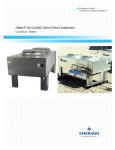
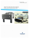
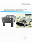
Precision Cooling
For Business-Critical Continuity™
Liebert VFD Condenser — Model TCDV™
Product Information Manual - 50/60Hz
TABLE OF CONTENTS
1.0
INTRODUCTION . . . . . . . . . . . . . . . . . . . . . . . . . . . . . . . . . . . . . . . . . . . . . . . . . . . . . . . . . .1
1.1
Description . . . . . . . . . . . . . . . . . . . . . . . . . . . . . . . . . . . . . . . . . . . . . . . . . . . . . . . . . . . . . . . . . 1
1.2
Application . . . . . . . . . . . . . . . . . . . . . . . . . . . . . . . . . . . . . . . . . . . . . . . . . . . . . . . . . . . . . . . . . 1
1.3
Features and Benefits . . . . . . . . . . . . . . . . . . . . . . . . . . . . . . . . . . . . . . . . . . . . . . . . . . . . . . . . 1
2.0
DIMENSIONAL AND ELECTRICAL DATA . . . . . . . . . . . . . . . . . . . . . . . . . . . . . . . . . . . . . . . .5
3.0
GUIDE SPECIFICATIONS . . . . . . . . . . . . . . . . . . . . . . . . . . . . . . . . . . . . . . . . . . . . . . . . . . .7
3.1
General . . . . . . . . . . . . . . . . . . . . . . . . . . . . . . . . . . . . . . . . . . . . . . . . . . . . . . . . . . . . . . . . . . . . 7
3.2
Coil . . . . . . . . . . . . . . . . . . . . . . . . . . . . . . . . . . . . . . . . . . . . . . . . . . . . . . . . . . . . . . . . . . . . . . . 7
3.3
Fans. . . . . . . . . . . . . . . . . . . . . . . . . . . . . . . . . . . . . . . . . . . . . . . . . . . . . . . . . . . . . . . . . . . . . . . 7
3.4
Fan Motors . . . . . . . . . . . . . . . . . . . . . . . . . . . . . . . . . . . . . . . . . . . . . . . . . . . . . . . . . . . . . . . . . 7
3.5
Head Pressure Control . . . . . . . . . . . . . . . . . . . . . . . . . . . . . . . . . . . . . . . . . . . . . . . . . . . . . . . . 7
3.6
Housing . . . . . . . . . . . . . . . . . . . . . . . . . . . . . . . . . . . . . . . . . . . . . . . . . . . . . . . . . . . . . . . . . . . . 7
3.7
TVSS and Unit Disconnect Switch . . . . . . . . . . . . . . . . . . . . . . . . . . . . . . . . . . . . . . . . . . . . . . 7
3.8
Alarm Contacts. . . . . . . . . . . . . . . . . . . . . . . . . . . . . . . . . . . . . . . . . . . . . . . . . . . . . . . . . . . . . . 7
3.9
Electrical Controls . . . . . . . . . . . . . . . . . . . . . . . . . . . . . . . . . . . . . . . . . . . . . . . . . . . . . . . . . . . 7
FIGURES
Figure 1
Figure 2
Figure 3
Figure 4
Liebert Model TCDV Condenser—2-fan . . . . . . . . . . . . . . . . . . . . . . . . . . . . . . . . . . . . . . . . . . . . . .
Major electrical control components . . . . . . . . . . . . . . . . . . . . . . . . . . . . . . . . . . . . . . . . . . . . . . . . .
Cabinet and anchor dimensional data—VFD control condensers, 50 and 60Hz. . . . . . . . . . . . . . .
Electrical field connections, VFD control condensers . . . . . . . . . . . . . . . . . . . . . . . . . . . . . . . . . . . .
1
2
5
6
TABLES
Table 1
Table 2
Table 3
Table 4
Table 5
Electrical data—50 and 60 Hz . . . . . . . . . . . . . . . . . . . . . . . . . . . . . . . . . . . . . . . . . . . . . . . . . . . . . .
VFD condensers for indoor units, 50 and 60Hz. . . . . . . . . . . . . . . . . . . . . . . . . . . . . . . . . . . . . . . . .
Condenser performance, 60Hz . . . . . . . . . . . . . . . . . . . . . . . . . . . . . . . . . . . . . . . . . . . . . . . . . . . . . .
Condenser performance, 50Hz . . . . . . . . . . . . . . . . . . . . . . . . . . . . . . . . . . . . . . . . . . . . . . . . . . . . . .
Physical data—VFD control condensers, 50 and 60Hz. . . . . . . . . . . . . . . . . . . . . . . . . . . . . . . . . . .
i
2
2
3
4
5
ii
Introduction
1.0
INTRODUCTION
1.1
Description
The Liebert VFD Control Condenser, Model TCDV, is an air cooled direct-drive refrigeration condenser designed to reject the heat from a precision air conditioning unit to the outdoor air. The condenser uses a Variable Frequency Drive (VFD) to control fan speed, which provides positive
refrigerant head pressure control for outdoor ambients as low as -20°F (-28.9°C).
Figure 1
1.2
Liebert Model TCDV Condenser—2-fan
Application
The VFD Control Condenser is applied to precision air conditioning units with dual refrigeration circuits, including units with digital scroll compressors.
1.3
Features and Benefits
• Variable Frequency Drive (VFD)—Programmed at the factory to integrate fluctuating head pressure signals created by compressor unloading, including digital scroll compressors, and varying
condenser capacity created by lower ambient temperatures.
• The VFD adjusts fan speed to provide stable fan speeds and condensing temperatures.
• Provides protection for motor overload and incoming power supply phase loss, undervoltage
and overvoltage.
• Built-in EMC filter—Electromagnetic emission levels comply with EN61800-3 (Second Environment - Light Industrial Applications).
• Inverter duty motor with permanently lubricated ceramic ball bearings for reliability
• Transducers on each circuit sense refrigerant pressures, providing input to the VFD
• Standard TVSS—Transient Voltage Surge Suppression increases condenser reliability by building in a layer of electrical protection against electrical failure caused by transient voltage surges
from unconditioned power sources and atmospheric discharges.
• Standard Locking disconnect
• Contacts for monitoring VFD and TVSS alarm conditions
• Available in 2-, 3- or 4-fan, dual-circuit condenser models
1
Introduction
Figure 2
Major electrical control components
Liebert’s
Transient
Voltage
Surge
Suppression
Variable
Frequency
Drive control
Locking
Disconnect
Table 1
Electrical data—50 and 60 Hz
Model #
165, 205
251, 308
415, 510
Number of Fans
2
3
4
Input Voltage
Ph
208/230
Hz
Motor Hp
FLA
WSA
OPD
FLA
WSA
OPD
FLA
WSA
OPD
7.2
8.1
15
10.7
11.6
15
14.2
15.1
20
60
460
3
200/230
0.75
50
380/415
3.5
4.0
15
5.2
5.7
15
6.9
7.4
15
7.2
*
*
10.7
*
*
14.2
*
*
3.5
*
*
5.2
*
*
6.9
*
*
FLA = Full Load Amps; WSA = Wire Size Amp; OPD = Maximum Overcurrent Protection Device Rating
* = Follow local electrical code to determine WSA and OPD
Table 2
VFD condensers for indoor units, 50 and 60Hz
R-22
R-407C
Outdoor Design Ambient Temperature
Indoor Unit
95°F (35°C)
100°F (38°C)
105°F (41°C)
95°F (35°C)
100°F (38°C)
105°F (41°C)
DH/VH75A
N/A
N/A
TCDV165
N/A
N/A
N/A
DH/VH114A
TCDV165
TCDV165
TCDV205
N/A
N/A
N/A
DH/VH125A
TCDV165
TCDV165
TCDV205
N/A
N/A
N/A
DH/VH199A
TCDV205
TCDV308
TCDV308
N/A
N/A
N/A
DH/VH245A
TCDV308
TCDV308
TCDV415
N/A
N/A
N/A
DH/VH290A
TCDV308
TCDV415
TCDV415
N/A
N/A
N/A
DH/VH380A
TCDV415
TCDV510
N/A
N/A
N/A
N/A
DS/VS028A
TCDV165
TCDV165
TCDV205
TCDV205
TCDV205
TCDV251
DS/VS035A
TCDV165
TCDV205
TCDV205
TCDV205
TCDV205
TCDV251
DS/VS042A
TCDV205
TCDV205
TCDV308
TCDV205
TCDV251
TCDV308
DS/VS053A
TCDV205
TCDV308
TCDV308
TCDV251
TCDV308
TCDV415
DS/VS070A
TCDV308
TCDV415
TCDV415
TCDV308
TCDV415
TCDV415
DS/VS077A
TCDV308
TCDV415
TCDV510
TCDV308
TCDV415
TCDV510
DS/VS105A
TCDV415
TCDV510
N/A
TCDV415
N/A
N/A
2
Introduction
Table 3
Condenser performance, 60Hz
Total Heat Rejection BTU/Hr (kW) Based on TD
Model
Number
30°F TD
(16.7°C)
25°F TD
(13.9°C)
20°F TD
(11.1°C)
15°F TD
(8.3C)
1°F TD
(0.6°C)
CFM
(CMH)
Sound
dBA
Fan
Qty
75.5
2
77.3
3
78.5
4
75.5
2
77.3
3
78.5
4
R-22 Refrigerant
TCDV165
178,410
(52.2)
148,675
(43.5)
118,940
(34.8)
89,205
(26.1)
5,947
(3.1)
13,300
(22,597)
TCDV205
264,930
(77.6)
220,775
(64.6)
176,620
(51.7)
132,465
(38.8)
8,831
(4.7)
11,200
(19,029)
TCDV251
298,170
(87.3)
248,475
(72.8)
198,780
(58.2)
149,085
(43.7)
9,939
(5.2)
20,250
(34,405)
TCDV308
384,180
(112.5)
320,150
(93.7)
256,120
(75.0)
192,090
(56.2)
12,806
(6.7)
18,600
(31,602)
TCDV415
507,690
(148.7)
423,075
(123.9)
338,460
(99.1)
253,845
(74.3)
16,923
(8.9)
24,800
(42,135)
TCDV510
552,240
(161.7)
460,200
(134.8)
368,160
(107.8)
276,120
(80.9)
18,408
(9.7)
19,200
(32,621)
R-407C Refrigerant
TCDV165
143,160
(41.9)
119,300
(34.9)
95,440
(27.9)
71,580
(21.0)
4772
(2.5)
(22,597)
TCDV205
242,100
(70.9)
201,750
(59.1)
161,400
(47.3)
121,050
(35.4)
8070
(4.3)
11,200
(19,029)
TCDV251
277,380
(81.2)
231,150
(67.7)
184,920
(54.1)
138,690
(40.6)
9246
(4.9)
20,250
(34,405)
TCDV308
337,890
(98.9)
281,575
(82.4)
225,260
(66.0)
168,945
(49.5)
11263
(5.9)
18,600
(31,602)
TCDV415
472,320
(138.3)
393,600
(115.3)
314,880
(92.2)
236,160
(69.2)
15744
(8.3)
(42,135)
TCDV510
452,820
(132.6)
377,350
(110.5)
301,880
(88.4)
226,410
(66.3)
15094
(8.0)
19,200
(32,621)
TD = Difference between Entering Air Temperature and Condensing Temperature
3
13,300
24,800
Introduction
Table 4
Condenser performance, 50Hz
Total Heat Rejection BTU/hr (kW) based on TD
Model
Number
30°F TD
(16.7°C)
25°F TD
(13.9°C)
20°F TD
(11.1°C)
15°F TD
(8.3°C)
1°F TD
(0.6°C)
CFM
(CMH)
Sound
dBA
Fan
Qty
71.0
2
72.8
3
74.0
4
71.0
2
72.8
3
74.0
4
R-22 Refrigerant
TCDV165
162,660
(47.6)
135,550
(39.7)
108,440
(31.8)
81,330
(23.8)
5,422
(2.9)
11,100
(18,859)
TCDV205
233,040
(68.2)
194,200
(56.9)
155,360
(45.5)
116,520
(34.1)
7,768
(4.1)
9,300
(15,801)
TCDV251
270,150
(79.1)
225,125
(65.9)
180,100
(52.7)
135,075
(39.6)
9,005
(4.7)
16,800
(28,543)
TCDV308
343,080
(100.5)
285,900
(83.7)
228,720
(67.0)
171,540
(50.2)
11,436
(6.0)
15,450
(26,250)
TCDV415
454,680
(133.1)
378,900
(110.9)
303,120
(88.8)
227,340
(66.6)
15,156
(8.0)
20,600
(35,000)
TCDV510
479,040
(140.3)
399,200
(116.9)
319,360
(93.5)
239,520
(70.1)
15,968
(8.4)
16,000
(27,184)
R-407C Refrigerant
TCDV165
129,960
(38.1)
108,300
(31.7)
86640
(25.4)
64,980
(19.0)
4,332
(2.3)
11,100
(18,859)
TCDV205
212,280
(62.2)
176,900
(51.8)
141520
(41.4)
106,140
(31.1)
7,076
(3.7)
9,300
(15,801)
TCDV251
250,920
(73.5)
209,100
(61.2)
167280
(49.0)
125,460
(36.7)
8,364
(4.4)
16,800
(28,543)
TCDV308
301,950
(88.4)
251,625
(73.7)
201300
(58.9)
150,975
(44.2)
10,065
(5.3)
15,450
(26,250)
TCDV415
422,400
(123.7)
352,000
(103.1)
281600
(82.5)
211,200
(61.8)
14,080
(7.4)
20,600
(35,000)
TCDV510
391,800
(114.7)
326,500
(95.6)
261200
(76.5)
195,900
(57.4)
13,060
(6.9)
16,000
(27,184)
TD = Difference between Entering Air Temperature and Condensing Temperature
4
Dimensional and Electrical Data
2.0
DIMENSIONAL AND ELECTRICAL DATA
Figure 3
Cabinet and anchor dimensional data—VFD control condensers, 50 and 60Hz
Eyebolts for lifting condenser
Provided on four-fan models only
43-9/16"
(1107mm)
A
70" (1778mm)
Height to top
of fan guard:
43-1/8" (1095mm)
37-7/8"
(962mm)
18" (457mm)
Disconnect
Switch
43-3/16"
(1097mm)
Cabinet Dimensions
Clearance of 36" (914.4mm) on all
sides is recommended for proper
operation and component access
B
D
C
4 legs furnished for 2- and 3-fan
models
6 legs furnished for 4-fan models
1-7/8”
(47.6mm)
37-11/16"
(957mm)
4-1/4”
(108mm)
Unit Anchor Plan
Typical Diameter
9/16" (14.3mm)
1-3/4”
(44.5mm)
1-7/8”
(47.6mm)
4-1/4”
(108mm)
1-3/4”
(44.5mm)
Typical Footprint
Table 5
1”
(25.4mm)
DPN001049
Rev. 0
Physical data—VFD control condensers, 50 and 60Hz
A
B
C
D
Net Weight
Model #
Number
of Fans
in (mm)
in (mm)
in (mm)
in (mm)
lb (kg)
TCDV165
2
91-1/2 (2324)
84 (2134)
82 (2083)
--
425 (193)
TCDV205
2
91-1/2 (2324)
84 (2134)
82 (2083)
--
495 (225)
TCDV251
3
131-1/2 (3340)
124 (3150)
122 (3099)
--
500 (227)
TCDV308
3
131-1/2 (3340)
124 (3150)
122 (3099)
--
670 (305)
TCDV415
4
171-1/2 (4356)
164 (4166)
82 (2083)
80 (2032)
815 (370)
TCDV510
4
171-1/2 (4356)
164 (4166)
82 (2083)
80 (2032)
1188 (540)
All condenser fan motors are 3/4 hp
5
Dimensional and Electrical Data
Figure 4
Electrical field connections, VFD control condensers
Factory-installed fuse block on
60Hz units. Circuit breaker supplied
in lieu of fuse block on 50Hz units.
Factory-wired to 24V
control circuit.
Control interlock (70, 71)
Field-supplied
Class 1 wiring to
interlock condenser 24V
controls to Liebert
room unit; 7/8 in.
(22.2mm) diameter
hole provided in
bottom of electric box.
Electric service connection
terminals with factorysupplied disconnect.
Factory-installed
disconnect switch.
Alarm Connections
Field-supplied 24V Class 1
wiring to remote alarm circuits
Variable Frequency Drive (VFD)
alarm contact connections (11, 12)
Transient Voltage Surge Suppressor (TVSS)
alarm contact connections (13, 14).
Electric service entrance.
A 7/8" (22.2mm) diameter
hole in a 1-1/8 in (28.6mm)
knockout provided in bottom
of electric box.
Factory wired to components
on electric panel.
Earth ground connection (60Hz).
Connection terminal for
Earth ground bar (optional on 50Hz only). field-supplied earth grounding wire
Connection terminals with factory
when factory disconnect is supplied.
ground from each high voltage
component for field-supplied
earth grounding wire.
Electric service,
not by Liebert
NOTE: Refer to specification sheet for Full Load Amp and Wire Size Amp ratings.
6
DPN001051
Rev. 0
Guide Specifications
3.0
GUIDE SPECIFICATIONS
3.1
General
Each condenser shall consist of housing, condenser coil, propeller fans direct-driven by individual fan
motors, fan guards, electrical controls and mounting legs. The air-cooled condenser shall have a
_____volt, 3-phase, _____ Hz power supply.
3.2
Coil
Liebert manufactured coil shall be constructed of copper tubes in a staggered tube pattern. Tubes are
expanded into continuous, corrugated aluminum fins. The fins have full depth fin collars completely
covering the copper tubes, which are connected to heavy wall Type "L" headers. Inlet coil connector
tubes pass through relieved holes in the tube sheet for maximum resistance to piping strain and
vibration. Coils are factory leak-tested at a minimum of 300 psig (2068kPag), dehydrated, then filled
with a nitrogen holding charge and sealed for shipment.
3.3
Fans
Fans shall have aluminum blades secured to corrosion protected steel hubs. Fans shall be secured to
the fan shaft by means of a heavy-duty keyed hub and dual setscrews. Fan diameter shall be 26"
(660mm) or less. Fans shall be factory balanced and run before shipment. Fan guards shall be heavy
gauge, close-meshed steel wire with corrosion resistant PVC finish that shall be rated to pass a
675-hour salt spray test.
3.4
Fan Motors
The variable speed fan motor shall be an inverter duty motor with permanently lubricated ceramic
bearings. The Liebert variable frequency drive control system shall provide overload protection for
the variable speed motor. Each ambient-temperature-controlled fan motor shall have built-in overload protection. All motors shall have rain slingers, permanently lubricated bearings and shall be rigidly mounted on die-formed galvanized steel supports.
3.5
Head Pressure Control
The Liebert VFD Condenser control system shall include a variable frequency drive, inverter duty fan
motor operating from 0% to 100% motor RPM based on head pressure, refrigerant pressure transducers, ambient-temperature thermostat(s), motor overload protection and electrical control circuit, factory-wired in the control panel. VFD control shall be furnished on the fan adjacent to the connection
end of the condenser, which runs continuously with the compressors. Other condenser fans shall be
controlled by ambient thermostats and are either On or Off. This system permits operation at temperatures as low as -20°F (-28.9°C).
3.6
Housing
The condenser housing shall be constructed of bright aluminum sheet and divided into individual fan
sections by full width baffles. Structural support members, including coil support frame, motor and
drive support, are galvanized steel for strength and corrosion resistance. Aluminum legs are provided
with rigging holes for hoisting the unit into position.
3.7
TVSS and Unit Disconnect Switch
Transient Voltage Surge Suppression and locking disconnect shall be factory-installed and wired in
the enclosed condenser electrical panel section.
3.8
Alarm Contacts
Normally open, dry contacts shall be provided for indication of VFD and TVSS alarm condition.
3.9
Electrical Controls
All electrical connections and controls shall be provided in a weatherproof enclosure. The enclosure
shall be integral with the condenser for pleasing appearance as well as functional protection.
7
Ensuring The High Availability
0f Mission-Critical Data And Applications.
Emerson Network Power, the global leader in enabling business-critical
continuity, ensures network resiliency and adaptability through
a family of technologies—including Liebert power and cooling
technologies—that protect and support business-critical systems.
Liebert solutions employ an adaptive architecture that responds
to changes in criticality, density and capacity. Enterprises benefit
from greater IT system availability, operational flexibility and
reduced capital equipment and operating costs.
Technical Support / Service
Web Site
www.liebert.com
Monitoring
800-222-5877
[email protected]
Outside the US: 614-841-6755
Single-Phase UPS
800-222-5877
[email protected]
Outside the US: 614-841-6755
Three-Phase UPS
800-543-2378
[email protected]
Environmental Systems
800-543-2778
Outside the United States
614-888-0246
Locations
United States
1050 Dearborn Drive
P.O. Box 29186
Columbus, OH 43229
Europe
Via Leonardo Da Vinci 8
Zona Industriale Tognana
35028 Piove Di Sacco (PD) Italy
+39 049 9719 111
Fax: +39 049 5841 257
Asia
7/F, Dah Sing Financial Centre
108 Gloucester Road, Wanchai
Hong Kong
852 2572220
Fax: 852 28029250
While every precaution has been taken to ensure the accuracy
and completeness of this literature, Liebert Corporation assumes no
responsibility and disclaims all liability for damages resulting from use of
this information or for any errors or omissions.
© 2007 Liebert Corporation
All rights reserved throughout the world. Specifications subject to change
without notice.
® Liebert and the Liebert logo are registered trademarks of Liebert
Corporation. All names referred to are trademarks
or registered trademarks of their respective owners.
SL-10065 _REV0_12-06
Emerson Network Power.
The global leader in enabling Business-Critical Continuity.
AC Power
Embedded Computing
Embedded Power
Connectivity
DC Power
Monitoring
Outside Plant
Power Switching & Controls
Precision Cooling
EmersonNetworkPower.com
Racks & Integrated Cabinets
Services
Surge Protection
Business-Critical Continuity, Emerson Network Power and the Emerson Network Power logo are trademarks and service marks of Emerson Electric Co.
©2007 Emerson Electric Co.