1
299H Series
Instruction Manual
Form 5497
January 2014
299H Series Pressure Reducing Regulators
!
WARNING
Failure to follow these instructions or
to properly install and maintain this
equipment could result in an explosion
and/or fire causing property damage and
personal injury or death.
Fisher® regulators must be installed,
operated and maintained in accordance
with federal, state and local codes, rules
and regulations and Emerson Process
Management Regulator Technologies, Inc.
(Regulator Technologies) instructions.
If the regulator vents gas or a leak
develops in the system, service to the unit
may be required. Failure to correct trouble
could result in a hazardous condition.
Call a gas service person to service the
unit. Only a qualified person must install
or service the regulator.
W7513
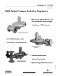
Figure 1. 299H Series Pressure Reducing Regulator
Introduction
Scope of the Manual
This Instruction Manual provides installation, adjustment
and maintenance instructions and parts ordering
information for the 299H Series regulators. Complete
instructions and parts list for the 67C Series filtered pilot
supply regulator and other Fisher equipment are found
in separate instruction manuals.
Description
The Type 299HS provides overpressure or overpressure
and underpressure protection by completely shutting off
the flow of gas to the downstream system. It comes with
a Type VSX-2 slam-shut device which can be configured
for Ovepressure Shutoff (OPSO) or Overpressure and
Underpressure Shutoff (OPSO/UPSO). The slam-shut
device’s actions are independent of the main valve and
of variations to the inlet pressure. The Type VSX-2
slam-shut device has internal or external registration.
External registration requires a downstream sensing line.
D102684X012
The 299H Series pressure reducing regulators provide
a broad capacity of controlled pressure ranges and
capacities in a wide variety of distribution, industrial
and commercial applications. A 299H Series regulator
has a pilot integrally mounted to the actuator casing.
The 299H Series regulators can handle inlet pressures
up to 175 psi / 12.1 bar depending on orifice size.
The integral token relief on the Types 299HR and
299HSR regulators is located in the pilot and opens
to relieve minor overpressure.
www.fisherregulators.com
299H Series
Specifications
Specifications for 299H Series constructions are given below. Some specifications for a given regulator as it
originally comes from the factory are stamped on a nameplate located on the actuator upper casing.
Available Constructions
Type 299H: Pilot-operated pressure reducing
regulator with a pilot integrally mounted to the
actuator casing.
Type 299HR: A Type 299H with a token internal
relief valve to relieve minor overpressure caused
by thermal expansion.
Type 299HS: Same as the Type 299H with a
Type VSX-2 slam-shut valve which provides
overpressure or overpressure and
underpressure protection.
Type 299HSR: Same as the Type 299HS with an
internal token relief valve.
Minimum and Maximum Trip Pressure Ranges
See Table 3
Body Size and End Connection Styles
See Table 1
Temperature Capabilities(1)
-20 to 150°F / -29 to 66°C
Maximum Operating Inlet Pressure by Orifice Size(1)
1/4 x 3/8-inch / 6.4 x 9.5 mm........... 175 psig / 12.1 bar
3/8 inch / 9.5 mm........................... 175 psig / 12.1 bar
1/2 inch / 13 mm............................ 175 psig / 12.1 bar
3/4 inch / 19 mm............................ 150 psig / 10.3 bar
7/8 inch / 22 mm(5)........................... 125 psig / 8.6 bar
1 inch / 25 mm(5)..................................100 psig / 6.9 bar
1-3/16 inches / 30 mm(5).................... 80 psig / 5.5 bar
Approximate Weight
21 pounds / 10 kg
Maximum Casing and Emergency Outlet Pressure(1)
66 psig / 4.5 bar
Outlet (Control) Pressure Ranges(1)(2)
See Table 2
Maximum Set Pressure for Type 299HS(1)
16 psig / 1.1 bar
Maximum Set Pressure for Slam-Shut Device(1)
23 psig / 1.6 bar
1.
2.
3.
4.
5.
Type VSX-2 Sensing Line Connection
1/4 NPT
Pressure Control Accuracy (Fixed Factor)(PFM)
±1%(3) of absolute control pressure
Minimum Differential Pressure For Full Stroke
1.5 psid / 0.10 bar d
Control Line Connections
3/4 NPT
Pressure Registration
Internal, External or Dual Registration
See Figure 2
Fixed Restriction Sizes
0.044 inch / 1.1 mm, Red (standard gain)
0.071 inch / 1.8 mm, Green (low gain)
0.082 inch / 2.1 mm, Blue (lower gain)
Options
• Filter(3): A P590 Series filter installed in the pilot
supply tubing between main body and pilot
• Filtered pilot supply regulator(3)(4): A Type 67CF
supply regulator with integral 5 micron
Polyethylene filter
The pressure/temperature limits in this Instruction Manual and any applicable standard or code limitation should not be exceeded.
For optimum performance, a pilot supply regulator may be installed in the pilot supply tubing between the main valve and pilot.
A pilot supply regulator or a P590 Series filter (only one may be used, not both) may be ordered with the Type 299H, but not both.
For inches w.c., use a pilot supply regulator if actual inlet pressure varies more than ±20 psi / ±1.4 bar and published accuracy is required.
This orifice size is not available for Types 299HS and 299HSR.
Table 1. Body Sizes and End Connection Styles
BODY MATERIAL AND END CONNECTION STYLE
BODY SIZE,
INCH / DN
Cast Iron (For Types 299H and 299HR only)
Ductile Iron
Steel (For Types 299H and 299HR only)
1-1/4
1-1/2
NPT
NPT
---NPT
---NPT
2 / 50
NPT and CL125 FF(1) flanged
NPT, CL125 FF and CL250 RF flanged
and PN 10/16 flanged
NPT and CL150 RF flanged
1. This flange is available with a face-to-face dimension of 7.5 inches / 190 mm or 10 inches / 254 mm.
2
299H Series
Table 2. Outlet Pressure Ranges
TYPE
OUTLET (CONTROL)
PRESSURE RANGE
PILOT CONTROL SPRING
299H
299HR,
299HS and
299HSR
Part Number
Color
Free Length
Wire Diameter
Inch w.c.
mbar
Inch
mm
Inch
mm
3.5 to 6(1)
5 to 9(1)
7 to 20(1)
16 to 40(1)
9 to 15(1)
12 to 22(1)
17 to 50(1)
40 to 99(1)
X
X
X
X
X
X
X
X
T13707T0012
T13589T0012
1N3112X0012
1B413727222
Black
Yellow
Unpainted
Purple
1.86
2.05
2.18
2.12
47.2
52.1
55.4
53.8
0.055
0.051
0.075
0.092
1.40
1.30
1.90
2.34
1 to 3.25 psig
2.75 to 6 psig
5 to 16 psig
14 to 35 psig
30 to 60 psig
69 mbar to 0.22 bar
0.19 to 0.41 bar
0.34 to 1.1 bar
0.97 to 2.4 bar
2.1 to 4.1 bar
X
X
X
X
X
X
X
X
-------
T13593T0012
T13671T0012
T13600T0012
19B0432X012
19B0432X022
Light blue
Orange
Red
Zinc
Green
2.12
2.40
2.10
2.15
2.75
53.8
61.0
53.3
54.6
69.8
0.105
0.120
0.142
0.207
0.225
2.67
3.05
3.61
5.26
5.71
1. Use a pilot supply regulator if actual inlet pressure varies more than ±20 psi / ±1.4 bar and the published accuracy is required.
Table 3. Type VSX-2 High and Low Trip Pressure Ranges
RANGE
High
Pressure
Trip
SLAM-SHUT
REGISTRATION
Internal or
External
External
FOR USE WITH MAIN VALVE
SPRING RANGE
Inch w.c.
mbar
3.5 to 6
9 to 15
5 to 9
12 to 22
3.5 to 6
9 to 15
5 to 9
12 to 22
7 to 20
17 to 50
7 to 20
17 to 50
16 to 40
40 to 99
16 to 40
40 to 99
1 to 3.25 psig
69 mbar to 0.22 bar
2.75 to 6 psig
0.19 to 0.41 bar
2.75 to 6 psig
0.19 to 0.41 bar
5 to 16 psig
0.35 to 1.1 bar
5 to 16 psig
0.35 to 1.1 bar
5 to 9
12 to 22
7 to 20
17 to 50
7 to 20
17 to 50
16 to 40
40 to 99
1 to 3.25 psig
69 mbar to 0.22 bar
2.75 to 6 psig
0.19 to 0.41 bar
2.75 to 6 psig
0.19 to 0.41 bar
5 to 16 psig
0.35 to 1.1 bar
Internal
SPRING FREE
LENGTH
SPRING WIRE
DIAMETER
Inch
mm
Inch
mm
Inch w.c.
mbar
TYPE VSX-2
SPRING PART
NUMBER
12 to 25
30 to 62
T14162T0012
3.15
80.0
0.07
1.70
20 to 52
50 to 129
T14163T0012
3.15
80.0
0.08
2.03
1.4 to 3.9 psig
97 to 269
T14164T0012
3.15
80.0
0.09
2.31
3.8 to 8.7 psig
262 to 600
T14165T0012
3.15
80.0
0.12
3.05
5.8 to 16 psig
400 to 1103
T14166T0012
3.15
80.0
0.14
3.51
11.6 to 23 psig
800 to 1586
T14167T0012
3.15
80.0
0.17
4.32
2 to 12
5 to 30
T14168T0012
3.15
80.0
0.04
1.09
4 to 30
10 to 75
T14169T0012
3.15
80.0
0.06
1.40
0.36 to 2.3 psig
25 to 159
T14170T0012
3.15
80.0
0.07
1.70
1.5 to 10.8 psig
103 to 745
T14171T0012
3.15
80.0
0.13
3.17
----
----
-----------
----
----
----
----
70% of regulator 70% of regulator
setpoint to
setpoint to
2.3 psig
159 mbar
T14170T0012
3.15
80.0
0.07
1.70
5 to 9
12 to 22
7 to 20(1)
17 to 50(1)
16 to 40(1)
40 to 99(1)
1 to 3.25 psig(2)
69 mbar to
0.22 bar(2)
2.75 to 6 psig(2)
0.19 to 0.41 bar(2)
2.75 to 6 psig(2)
0.19 to 0.41 bar(2)
70% of regulator 70% of regulator
setpoint to
setpoint to
10.8 psig
745 mbar
T14171T0012
3.15
80.0
0.13
3.17
5 to 16 psig(3)
0.35 to 1.1 bar(3)
75% of regulator 75% of regulator
setpoint to
setpoint to
10.8 psig
745 mbar
T14171T0012
3.15
80.0
0.13
3.17
(1)
Low
Pressure
Trip
MINIMUM TO MAXIMUM
TRIP PRESSURE
(1)
1. Low Pressure Trip cannot be used with this main valve spring range for an internally registered Type VSX-2 to provide underpressure shutoff under flowing conditions. If protection
against loss of inlet pressure is the only required function for the Type VSX-2 then an internally registered Type VSX-2 may be used with the same minimum trip pressures as an
externally registered Type VSX-2.
2. 70% of regulator setpoint is the minimum allowable Low Pressure Trip setting for an internally registered Type VSX-2 used with this main valve spring range. If protection against
loss of inlet pressure is the only required function for the Type VSX-2 then an internally registered Type VSX-2 may be used with the same minimum trip pressures as an externally
registered Type VSX-2.
3. 75% of regulator setpoint is the minimum allowable Low Pressure Trip setting for an internally registered Type VSX-2 used with this main valve spring range. If protection against
loss of inlet pressure is the only required function for the Type VSX-2 then an internally registered Type VSX-2 may be used with the same minimum trip pressures as an externally
registered Type VSX-2.
Note: Other spring combinations are available, please contact your local Sales Office for additional information.
3
299H Series
H992 epyT
B
J
B
noitartsigeR l
J
E
OUTLET
E
OUTLET
H
H
J
3/4 NPT
DOWNSTREAM
CONTROL LINE
CONNECTION
INLET
INLET
3/4 NPT
CONTROL LINE
CONNECTION
G
EXTERNAL REGISTRATION
3/4 NPT
CONTROL LINE
CONNECTION
PILOT SUPPLY
SCREEN
PILOT SUPPLY
G
SCREEN
G
C
K
C
K
A
F
A
F
J
3/4 NPT
DOWNSTREAM
CONTROL LINE
CONNECTION
INTERNAL
REGISTRATION
E0070
G
DUAL REGISTRATION
INLET PRESSURE
8600E
E0070
OUTLET PRESSURE
ATMOSPHERIC PRESSURE
LOADING PRESSURE
TYPE 299H
A7272
A7272
TOKEN RELIEF CLOSED
TOKEN RELIEF OPEN
TYPE 299HR (TOKEN RELIEF DETAIL)
Figure 2. 299H Series Operational Schematics
4
July 2008
July 2008
Type 299HS
299HS
Type
299H Series
B
J
E
OUTLET
TION
H
E0069
EXTERNAL REGISTRATION
EXTERNAL
REGISTRATION
EXTERNAL
REGISTRATION
INLET
3/4 NPT
CONTROL LINE
CONNECTION
PILOT SUPPLY
SCREEN
G
E0070
K
C
INTERNALAREGISTRATION
F
INTERNAL REGISTRATION
INTERNAL REGISTRATION
TION
INLET PRESSURE
TYPE 299HS
OUTLET PRESSURE
ATMOSPHERIC PRESSURE
LOADING PRESSURE
INLET PRESSURE
INLET
PRESSURE
OUTLET
PRESSURE
OUTLET
PRESSURE
ATMOSPHERIC
PRESSURE
ATMOSPHERIC
PRESSURE
LOADING PRESSURE
LOADING PRESSURE
E0072
E0072
Figure 2. 299H Series Operational Schematics (continued)
Principle of Operation
!
WARNING
Since a pilot-operated regulator is
constructed of both a pilot and a main
valve, do not exceed the maximum inlet
pressure shown on the nameplate.
Letter keys in this section refer to Figure 2 unless
otherwise noted. Fast response and accuracy are
made possible by the amplifying effect of the pilot
and by the two-path control system. The function of
the pilot is to sense change in the controlled pressure
and amplify it into a larger change in the loading
pressure. Any changes in outlet pressure act quickly
on both the actuator diaphragm and the loading pilot,
thus providing the precise pressure control that is
characteristic of a two-path control system.
Upstream or inlet pressure is utilized as the operating
medium, which is reduced through pilot operation to load
the main diaphragm chamber. Tubing connects the inlet
pressure to the pilot. Downstream or outlet pressure
registers underneath the main diaphragm (E) and on top
of pilot diaphragm (F). There are three different versions
of pressure registration for the 299H Series.
Internal registration—Outlet pressure is registered
through the throat (J) to the main diaphragm chamber
and then through a small port (G) to the top of the
pilot diaphragm.
External registration—The throat (J) is blocked and a
downstream control line is connected to the pilot upper
diaphragm chamber or the actuator lower diaphragm
chamber. A small port (G) connects the two chambers.
Dual registration—The lower main diaphragm chamber
registers outlet pressure through the throat (J) and the
upper pilot diaphragm chamber registers downstream
pressure by using a downstream control line. The port (G)
between the chambers is blocked.
Type 299H
In operation, assume the outlet pressure is less than
the setting of the pilot control spring (A). The top side
of pilot diaphragm assembly (F) will have a lower
pressure than the setting of the control spring (A).
The control spring (A) forces the diaphragm assembly
upward, opening the pilot orifice (C). Additional loading
pressure is supplied from the pilot orifice to the top side
of the main diaphragm (E).
5
299H Series
This creates a higher pressure on the top side of the
main diaphragm (E) than on the bottom side, forcing
the diaphragm downward. This motion is transmitted
through a lever, which pulls the valve disk (K) open,
allowing inlet pressure to flow through the valve.
When the demand in the downstream system has been
satisfied, the outlet pressure increases. The increased
pressure is transmitted through the downstream control
line (for external or dual registration) or through the
port (G) (for internal registration) and acts on top of the
pilot diaphragm (F). This pressure exceeds the pilot
spring setting and forces the diaphragm down, closing
the orifice (C). The loading pressure acting on the
main diaphragm (E) bleeds to the downstream system
through a bleed restriction (H).
With a decrease in loading pressure on top of the
main diaphragm (E), the main closing spring (B)
exerts an upward force on the diaphragm post which
is connected to the main diaphragm (E), pulling it
upward. This moves the main valve disk (K) toward its
seat, decreasing flow to the downstream system.
Type 299HR
During normal operation the Type 299HR performance
is identical to the Type 299H. If an overpressure
condition occurs, the pilot diaphragm head will
separate from the pilot diaphragm post and travel until
it contacts the pilot spring case. The movement of the
diaphragm head creates a path and a token or small
amount of gas will be released.
When the overpressure condition ceases, the pilot
diaphragm head will return to the diaphragm post and
the regulator will return to normal operation.
Type 299HS
The Type VSX-2 slam-shut device on the Type 299HS
regulator is a fast acting slam-shut valve which provides
overpressure or overpressure and underpressure
protection by completely shutting off the flow of gas to
the downstream system. The slam-shut module’s actions
are independent of the Type 299HS main regulator and
of the variations to the inlet pressure. The Type VSX-2
has internal or external registration. External registration
requires a downstream sensing line.
The slam-shut disk is held in the open position (reset
position) by a small ball holding the disk stem. If
the pressure below the diaphragm increases (or
decreases) reaching the Type VSX-2 setpoint,
the diaphragm will travel upwards (or downwards)
operating a lever which in turn releases the ball.
6
Once the ball is released, the spring force on the stem
will push the stem and disk to the closed position
against the seat shutting off all gas flow. The pilot
supply pressure is also shut off when the Type VSX-2
is closed. The manual reset has an internal bypass to
equalize the reset pressure on either side on the
slam-shut disk.
In order for the Underpressure Shutoff (UPSO) of
any slam shut to be triggered, the downstream pipe
pressure must drop below the UPSO setpoint. In the
case of a downstream line break, numerous factors
can prevent the downstream pipe pressure from
decreasing below the slam-shut UPSO setpoint. These
factors include the distance of pipe to the break, the
diameter of the pipe, size of the break and the number
of restrictions, such as valves, elbows and bends,
downstream of the regulator and/or slam-shut device.
Due to these factors additional protections should be
installed to stop flow in the event of a line break.
Overpressure Protection
Like most regulators, the Type 299H has outlet
pressure ratings lower than the inlet pressure ratings.
Complete downstream overpressure protection is
needed if the actual inlet pressure exceeds the outlet
pressure rating.
Overpressure protection for internal parts is built
into the main and pilot diaphragms by means of a
small spring on each post. The springs will allow
the diaphragm heads to move farther on the posts
avoiding damage to or bending of the valve trim.
Overpressuring any portion of a regulator or
associated equipment may cause leakage, parts
damage or personal injury due to bursting of
pressure-containing parts or explosion of accumulated
gas. Regulator operation within ratings does not
preclude the possibility of damage from external
sources or from debris in the pipeline. A regulator
should be inspected for damage periodically and after
any overpressure condition.
The pilot vent is provided with a 1/4 NPT tapped
connection in the spring case.
Installation
!
WARNING
Personal injury, equipment damage or
leakage due to escaping gas or bursting
of pressure-containing parts might result
299H Series
if this regulator is overpressured or is
installed where service conditions could
exceed the limits for which the regulator
was designed or where conditions exceed
any ratings of the adjacent piping or
piping connections. To avoid such injury
or damage, provide pressure-relieving
or pressure-limiting devices (as required
by the appropriate code, regulation or
standard) to prevent service conditions
from exceeding those limits.
A regulator may vent some gas to the
atmosphere in hazardous or flammable
gas service. Vented gas might accumulate
and cause personal injury, death or
property damage due to fire or explosion.
Vent a regulator in hazardous gas service
to a remote, safe location away from air
intakes or any hazardous location. Protect
the vent line or stack opening against
condensation or clogging.
If the regulator is exposed to an
overpressure condition, it should be
inspected for any damage that may have
occurred. Operation below these limits
does not preclude the possibility of
damage from external sources or from
debris in the pipeline.
If the Type VSX-2 is exposed to an
overpressure condition, it should be
inspected for any damage that may have
occurred. Operation below these limits
does not preclude the possibility of
damage from external sources or from
debris in the pipeline.
In the case of a downstream line break,
numerous factors affect the capability
to evacuate gas from the pipeline.
These factors include the distance of
pipe to the break, the diameter of the
pipe, size of the break and the number
of restrictions, such as valves, elbows
and bends, downstream of the regulator
and/or slam-shut device. Due to these
factors additional protections should be
installed to stop flow in the event of a
line break.
Like most regulators, the 299H Series regulators have
an outlet pressure rating lower than its inlet pressure
rating. Complete downstream overpressure protection
is needed if the actual inlet pressure can exceed the
regulator outlet pressure rating or the pressure ratings
of any downstream equipment. Regulator operation
within ratings does not preclude the possibility of
damage from external sources or from debris in the
lines. A regulator should be inspected for damage
periodically and after any overpressure condition.
Clean out all pipelines before installation. Check for
damage which might have occurred during shipment.
Also, check for and remove any dirt or foreign material
which may have accumulated in the regulator body.
Apply pipe compound to the external pipe threads of
threaded bodies or use suitable line gaskets and good
bolting practices with a flanged body. This regulator
may be installed in any position desired as long as the
flow through the body is in the direction indicated by the
arrow on the body. Install a three-valve bypass around
the regulator if continuous operation is necessary during
maintenance or inspection.
Although the standard orientation of the actuator and
pilot to the main valve body is as shown in Figure 1,
this orientation may be changed in 90° intervals by
rotating the actuator lower casing (key 1, Figure 6) and
the elbow fitting (key 19) by 90° and then reinstalling
the cap screws.
To keep the pilot spring case from being plugged or the
spring case from collecting moisture, corrosive chemicals
or other foreign material, the vent must be pointed down
oriented to the lowest possible point on the spring case
or otherwise protected. Vent orientation may be changed
by rotating the pilot spring case with respect to the
pilot body.
To remotely vent the pilot, remove the screwed-in vent
assembly (key 27, Figure 5) from the pilot spring case
and install obstruction-free tubing or piping into the
1/4 NPT vent tapping. Provide protection on a remote
vent by installing a screened vent cap into the remote
end of the vent pipe.
An upstream pilot supply line is not required
because of the integral pilot supply tubing (key 21,
Figure 6). However, as long as the 1/4 NPT tapping
in the main valve body is plugged, this tubing may
be disconnected from the main valve (key 17) in
order to install a pilot supply line from a desired
remote location into the pilot.
If using a control line, attach the control line from the
pilot tap 2 to 3 feet / 0.61 to 0.91 meters downstream
of the regulator in a straight run of pipe. If impossible
to comply with this recommendation due to the pipe
arrangement, it may be better to make the control line
tap nearer the regulator outlet rather than downstream
of a block valve. Do not make the tap near any elbow,
swage or nipple which might cause turbulence. For
optimal performance, use as large of a control line
as practical.
7
299H Series
In many instances, it will be necessary to enlarge the
downstream piping to keep flow velocities within good
engineering practices. Expand the piping as close to
the regulator outlet as possible.
!
WARNING
Adjustment of the pilot control spring to
produce an outlet pressure higher than
the upper limit of the outlet pressure
range for that particular spring can cause
personal injury or equipment damage due
to bursting of pressure-containing parts
or the dangerous accumulation of gases
if the maximum actuator emergency
casing pressure is exceeded. If the
desired outlet pressure is not within the
range of the pilot control spring, install a
spring of the proper range according to
the Maintenance section.
Each regulator is factory-set for the pressure setting
specified on the order. If no setting was specified,
the outlet pressure is set midrange of the pilot control
spring. In all cases, check the control spring setting to
make sure it is correct for the application.
Registration Conversion
To convert the 299H Series regulators from one type of
registration to another, all that is required is adding or
removing screws and O-rings.
To change an internal registration regulator to an
external registration regulator with a downstream
control line, block the two ports in the throat with
screws and O-rings (J in Figure 2). Remove either the
3/4 NPT pipe plug in the pilot casing or the 3/4 NPT
pipe plug in the lower casing and add a downstream
control line.
To convert an external registration regulator to a dual
registration regulator, remove the two screws and
O-rings (J in Figure 2) from the throat and use a screw
and an O-ring to block the port (G in Figure 2) between
the lower diaphragm chamber and pilot diaphragm
chamber. Remove the 3/4 NPT pipe plug in the pilot
lower casing and add a downstream control line.
Type VSX-2 Slam-Shut Device
To convert the Type VSX-2 from one type of
registration to another, all that is required is adding or
removing a screw and gasket.
To change an internal registration Type VSX-2 to an
external registration Type VSX-2 with downstream
8
control line, block the body pitot tube with a screw
and gasket (keys 10 and 11, Figure 7). Remove the
pipe plug in the Type VSX-2 and add a downstream
control line.
Type VSX-2 Installation
Note
The Type VSX-2 slam-shut module
should be mounted so that the spring
case vent points towards the ground.
Keys are referenced in Figure 7. Place new O-rings
(keys 2 and 3) on the Type VSX-2 and slide the
module into the Type 299HS body (key 17). Secure
the Type VSX-2 to the Type 299HS body with the four
set screws (key 4). The Type VSX-2 device may be
oriented in any direction with respect to the sensor
line connection.
Startup
With proper installation completed and downstream
equipment properly adjusted, perform the following
procedure while monitoring the pressure with gauges.
1. Very slowly open the upstream block valve.
2. On a Type 299HS, the Type VSX-2 is shipped in
the tripped position and will need to be reset. If the
Type VSX-2 is a high trip only, it can be reset before
starting the regulator. If the Type VSX-2 is a high
and low trip, the regulator will need to be started
and the downstream system pressurized before the
Type VSX-2 can be reset. See the section for
Type VSX-2 reset.
3. Slowly open the hand valve (if used) in the
control line. The regulator will control downstream
pressure at the pilot control spring setting. See
the Adjustment section following these numbered
steps if changes in the setting are necessary
during the start-up procedure.
4. Slowly open the downstream block valve.
5. Slowly close the bypass valve, if used.
6. Check all connections for leaks.
Adjustment
Keys are referenced in Figure 4. The only adjustment
on a 299H Series regulator is the reduced pressure
setting of the pilot control spring (key 32). Remove
the closing cap (key 29) and turn the adjusting screw
299H Series
(key 36). Turning the adjusting screw clockwise into
the spring case increases the controlled or reduced
pressure setting. Turning the screw counterclockwise
decreases the reduced pressure setting. Always
tighten the locknut (key 35) and replace the closing
cap after making adjustments.
Type VSX-2 Reset
Note
The overpressure and underpressure
trip points can only be reset if the
Type 299HS outlet pressure is between
the overpressure and underpressure
trip points.
Use the following procedure to reset the Type VSX-2:
1. Unscrew the brass resetting knob to open the
equalizing bypass.
2. Pull out the knob until it stops. This resets the
tripping mechanism.
3. Push in and tighten the knob.
Type VSX-2 Trip Adjustment
Note
An adjustment tool is included with the
Type VSX-2 (see Figure 8). Use only
this tool to make adjustments to the
Type VSX-2. To make adjustments, the
overpressure trip spring (key 7, Figure 7)
is found under the outer adjusting screw
and the underpressure trip spring (key 8)
is found under the inner adjusting screw.
Use the following procedure to adjust the Overpressure
Trip Spring:
1. Use the Type VSX adjusting tool to adjust
the overpressure trip spring to its maximum
compression (see Figure 8).
2. If present, adjust the underpressure spring
(using the Type VSX adjusting tool) to its
minimum compression.
3. Backpressure the unit with the desired
overpressure trip pressure.
4. Reduce the overpressure trip spring compression
until the Type VSX-2 trips.
Use the following procedure to adjust the Underpressure
Trip Spring:
1. Use the Type VSX adjusting tool to
adjust the underpressure trip spring to its
minimum compression.
2. Backpressure the unit with the desired
underpressure trip pressure.
3. Increase the underpressure trip spring
compression (using the Type VSX adjusting tool)
until the Type VSX-2 trips.
Shutdown
Installation arrangements may vary, but in any installation
it is important to open and close valves slowly and the
outlet pressure be vented before venting inlet pressure to
prevent damage caused by reverse pressurization of the
regulator. Isolate the regulator from the system. Vent the
downstream pressure; then vent inlet pressure to release
any remaining pressure in the regulator.
Maintenance
Regulator parts are subject to normal wear and must
be inspected periodically and replaced as necessary.
The frequency of inspection and replacement depends
upon the severity of service conditions and upon
applicable codes and government regulations.
Due to the care Regulator Technologies takes in
meeting all manufacturing requirements (heat treating,
dimensional tolerances, etc.), use only replacement parts
manufactured or furnished by Regulator Technologies.
!
WARNING
Avoid personal injury or damage
to property from sudden release
of pressure or uncontrolled gas or
other process fluid. Before starting
to disassemble, carefully release all
pressures according to the Shutdown
procedure. Use gauges to monitor inlet,
loading and outlet pressures while
releasing these pressures.
On reassembly of the regulator, it is recommended
that a good quality pipe thread sealant be applied to
pressure connections and fittings and a good quality
lubricant be applied to all O-rings. Also apply an antiseize compound to the adjusting screw threads and
other areas as needed.
9
299H Series
Note
The regulator body may remain in the
pipeline during maintenance procedures.
Main Actuator Diaphragm
Follow this procedure to change the actuator
diaphragm or to inspect, clean or replace any other
parts in the main actuator. Part key numbers are
referenced in Figures 5 and 6.
1. Cut the wire seal (key 68) (being careful not to
lose the warning tag) and remove the closing cap
(key 3). Inspect the O-ring (key 9) and replace
if necessary.
2. Carefully loosen and remove the double nuts
(key 5) on the actuator diaphragm post (key 10).
When removing the adjusting nuts, do not twist
or unscrew the diaphragm post, as this action will
loosen the joint between the diaphragm post and
the pusher post (keys 10 and 11).
3. Remove the spring seat (key 4) and closing spring
(key 6).
4. Remove the eight hex head cap screws (key 23)
and lift off the upper casing (key 2).
5. Remove the diaphragm assembly (key 8) by
tipping it so that the lever (key 26) slips out of the
pusher post (key 11).
6. Separate the diaphragm assembly by unscrewing
the diaphragm post (key 10) from the pusher
post (key 11) and remove the diaphragm post,
pressure equalization spring (key 7), diaphragm
head (key 81), diaphragm (key 8), the second
diaphragm head (key 81) and diaphragm pad
(key 80). Inspect the diaphragm parts for damage
and replace if necessary.
7. Inspect the lever (key 26) and replace if necessary.
To replace the valve stem (key 16), also perform
Main Body Valve Disk and Orifice maintenance
procedure steps 1, 2 and 3, remove disk (key 13)
and pull the stem out of the lower casing assembly
(key 1). Lightly lubricate the replacement stem
O-ring (key 14) and install it on the valve stem.
Reinstall the valve stem into the lower casing
assembly. Reinstall the body (key 17) or continue
with the reassembly of the diaphragm.
Note
When assembling the diaphragm assembly
(keys 8, 80 and 81), lubricate the actuator
diaphragm post (key 10) threads.
10
8. Loosely reassemble the diaphragm and diaphragm
post parts so that the bolt holes in the diaphragm
align with the corresponding holes in the lower
casing (key 1) when the lever (key 26) is fitted
properly into the pusher post. When this orientation
is made, tighten the diaphragm post into the pusher
post (keys 10 and 11).
9. Reinstall the diaphragm assembly using the
reverse order of step 5.
10. Install the upper casing (key 2) and secure it to the
lower casing (key 1) with the eight hex head screws
(key 23). Tighten the hex head screws evenly using
a crisscross pattern to avoid placing an uneven
strain on the regulator. Tighten the screws to a final
bolt torque of 10 to 13 foot-pounds / 13 to 17 N•m
to avoid crushing the diaphragm.
CAUTION
In step 11, the spring seat (key 4) is
under spring pressure. Use constant
hand pressure to hold the spring down
when installing the hex nuts (key 5), see
Figure 5.
11. Install the closing spring (key 6) and the spring seat
(key 4). Push and hold down on the spring seat,
cocking it to one side until the seat catches onto the
threads of the diaphragm post (key 10). Then, pull
up on the diaphragm post allowing access to the
post threads so that the two adjusting hex nuts
(key 5) can be installed. Install the adjusting hex
nuts as shown in Figure 5. The closing spring must
be adjusted down to a depth of 1/2-inch / 13 mm
from the top of the upper case opening to the top
of the spring seat. When tightening the two hex
nuts, use care not to rotate the diaphragm post,
which may damage the post.
12. Lightly lubricate the O-ring (key 9) on the closing
cap and reinstall the closing cap (key 3).
!
WARNING
The wire seal and warning tag (keys 68
and 69) contain important safety
information, make sure they are attached
when maintenance is completed.
13. Install the wire seal and warning tag (keys 68
and 69).
299H Series
Main Body Valve Disk and Orifice
6
5
2
5
Follow this procedure to inspect, clean or replace
the main body valve disk or to inspect or replace the
orifice. Part key numbers are referenced in Figures 5
and 6.
Note
The regulator body may remain in the
pipeline during maintenance procedures.
1. Disconnect the pilot supply tubing (key 21) from
the main body (key 17).
2. Remove the two hex head cap screws (key 18)
which hold the lower casing (key 1) to the body.
Separate the lower casing from the body. Inspect
the body O-ring (key 15) and replace if worn
or damaged.
3. Examine the valve disk (key 13) and orifice (key 12)
for nicks, cuts and other damage. Unscrew the disk
holder assembly from the valve stem assembly
(key 16) and replace it with a new part if necessary.
For the Type 299HS, also examine the insert and
O-ring (keys 82 and 83, Figure 7) for any damage.
Replace if needed.
If the orifice is being replaced with a new or
differently sized orifice, change the nameplate
(key 63) to state the new size and maximum
inlet pressure. Lubricate the threads and flat
face of the orifice with a good grade of anti-seize
lubricant. Install the orifice using 100 to
120 foot-pounds / 136 to 163 N•m of torque.
4. After replacing all damaged parts, slide the entire
assembly into the valve body (key 17) and secure
with the two hex head cap screws (key 18).
5. Connect the pilot supply tubing (key 21), then refer
to the Startup section for putting the regulator
into operation.
Integral Pilot Valve Disk and Orifice
Follow this procedure to inspect, clean or replace the
integral pilot valve disk or orifice. Part key numbers are
referenced in Figures 5 and 6.
1. Remove or loosen the pilot supply tubing (key 21).
2. Remove the inlet fitting (key 47) and the four
machine screws (key 46).
3. Examine the valve disk (key 52) for nicks, cuts and
other damage. Unscrew the disk holder assembly
from the valve stem (key 48) and replace
if necessary.
7
1
4
3
A7008
KEY 72 - OPTIONAL P590 SERIES FILTER
Figure 3. Optional P590 Series Filter
4. If the seating edge of the orifice (key 50) is nicked
or rough, use a thin-walled socket to remove the
orifice from the inlet fitting (key 47). Install a new
orifice and a lightly lubricated O-ring (key 49) when
reassembling the regulator.
5. Inspect the check valve assembly (key 45) and
the bleed restriction (key 70) for damage and
replace if necessary.
6. The Type 299H has a wire inlet screen (key 51)
in the pilot supply inlet fitting (key 47). If clogging
is suspected in the pilot supply, remove the elbow
fitting (key 19) and clean the wire screen.
7. Lightly lubricate the O-ring (key 54) on the inlet
fitting (key 47) and reinstall using the four machine
screws (key 46). Torque the machine screws to
30 to 40 inch-pounds / 3.4 to 4.5 N•m. Then install
and tighten the pilot supply tubing.
Integral Pilot Control Spring and Diaphragm
Follow this procedure to change the pilot control spring
or to inspect, clean or replace the diaphragm. Part key
numbers are referenced in Figures 4, 5 and 6.
1. Remove the pilot closing cap (key 29) and
loosen the hex lock nut (key 35). Turn the
adjusting screw (key 36) counterclockwise to
ease spring compression.
2. Unscrew the bonnet (key 34).
11
299H Series
3. Remove the bonnet (key 34), spring seat (key 33)
and control spring (key 32).
4. If only replacing the control spring (key 32),
sparingly apply lubricant to the control spring seat
(key 33) and reassemble in the reverse order.
Note
When replacing the control spring with
a different spring range, be sure to
delete the spring range appearing on the
nameplate and indicate the new range.
5. Remove the machine screws (key 30) and spring
case (key 31) from the lower casing (key 1).
6. Remove the diaphragm assembly (key 28) by tilting
them so that the pusher post (key 40) slips off the
lever (key 57). To separate the diaphragm from the
attached parts, unscrew the hex nut (key 37) and
separate the parts: washer (key 38), diaphragm
post (key 39), pusher post (key 40), overtravel
spring (key 41), machine screw (key 42), spring
seat (key 88) (Types 299HR and 299HSR), rivet
(key 43) and retaining ring (key 44).
7. To replace the lever assembly (key 57), remove the
lever pin (key 25). To replace the valve stem
(key 48), also perform Integral Pilot Valve Disk and
Orifice maintenance procedure steps 1, 2 and 3
and pull the stem (key 48) out of the lower casing
assembly (key 1). Lightly lubricate the replacement
stem O-ring (key 53) and install it on the valve stem.
8. Install the valve stem (key 48) into the lower
casing assembly (key 1). Be careful not to cut the
O-ring (key 53) when sliding the valve stem into
the lower casing.
9. Reinstall the diaphragm (key 28) assembly using
the reverse order of step 6.
10. Place the spring case (key 31) on the lower casing
(key 1) with the vent (key 27) oriented downwards
to prevent clogging or entrance or moisture. Install
the machine screws (key 30) and tighten in a
crisscross pattern using 12 to 18 inch-pounds /
1.4 to 2.0 N•m of torque.
12
11. When all maintenance is complete, refer to the
Startup section to put the regulator back into
operation and adjust the pressure setting. Tighten
the locknut (key 35) and install the closing cap
(key 29).
Type VSX-2 Maintenance
Parts numbers are referenced in Figure 7. The
Type VSX-2 device (key 1) is designed to be
removed as a unit from the Type 299HS body
(key 17) and be replaced as a complete unit. The
only replaceable parts in the Type VSX-2 module
are the O-rings (keys 2 and 3) and the high and
low pressure springs (keys 7 and 8). The high and
low pressure springs may be adjusted or replaced
without removing the slam-shut device from the
Type 299HS body.
Optional P590 Series Filter
Keys are referenced in Figures 3 and 6. If clogging
is suspected in the upstream regulator passages,
disconnect the pilot supply tubing (key 21, Figure 6),
remove the filter assembly (key 72) and check for filter
clogging. If necessary, to clean or replace filter parts,
remove the following: filter body (key 1), machine
screw (key 4), spring washer (key 6), gasket
(key 7), washer (key 5) and filter element (key 2).
Upon reassembly, place one flat washer (key 5)
between the filter element and filter head (key 3) and
the other between the filter element and gasket.
Optional Type 67CF Pilot Supply
Regulator
For complete installation, maintenance and parts list
refer to the 67C Series Instruction Manual.
Parts Ordering
The type number, orifice size, spring range and date of
manufacture are stamped on the nameplate. Provide
this information along with the eleven-character part
number to your local Sales Office when ordering parts.
If construction changes are made in the field, be sure
that the nameplate is also changed to reflect the most
recent construction.
299H Series
40
40
39
39
43
43
44
44
42
L2
L2
A
28
29
32
42
33
33
34
34
35
35
35
36
36
36
T80391-6
29
T80391-6
TYPE 299H PILOT WITHOUT RELIEF VALVE
TYPE 299HR PILOT WITH TOKEN RELIEF VALVE
APPLY ANTI-SEIZE COMPOUND (L2) / ADHESIVE (A)
Figure 4. 299H Series Pilot Assemblies
Parts List
Key Description
299H Series Regulator (Figures 4, 5 and 6)
Key Description
Parts Kit (Includes keys 8, 9, 13, 14, 15, 28,
49, 52, 53, 54, 60, 61 and 80) 1
Lower Casing, Aluminum
2
Upper Casing, Aluminum
3
Closing Cap, Aluminum
4
Spring Seat, Steel
5
Adjustment Nut, Steel (2 required)
6
Closing Spring, Steel
7
Pressure Equalization Spring, Steel
8*
Diaphragm, Nitrile (NBR)
9*
O-ring, Nitrile (NBR)
10
Diaphragm Post, Steel
11
Pusher Post, Aluminum
12
Orifice, Aluminum
1/4 x 3/8 inch / 6.4 x 9.5 mm
3/8 inch / 9.5 mm
1/2 inch / 13 mm
3/4 inch / 19 mm
7/8 inch / 22 mm (for Types 299H and 299HR only)
1 inch / 25 mm
(for Types 299H and 299HR only)
1-3/16 inches / 30 mm
(for Types 299H and 299HR only)
13* Disk, Nitrile (NBR)
14* O-ring, Nitrile (NBR)
* Recommended spare part
Part Number
R299X000012
T80447T0012
T40577T0012
1L928308012
T13831T0012
1A341224122
T13918T0012
T13463T0012
T20986T0012
1F914106992
T13814T0012
1L143311992
T13833T0012
1H979309022
1H979409022
1H979509022
T14098T0012
1H979609022
1H979709022
1P7349000A2
1E216306992
A
41
32
42
33
35
28
A
41
L2
L2
34
34
36
28
88
88
32
33
29
A
37
37
32
29
38
38
38
38
28
37
37
41
41
44
44
39
39
42
43
43
40
40
Part Number
15* O-ring, Nitrile (NBR)
T12587T0012
16
Valve Stem Assembly
1L1426000A2
17
Valve Body
Cast Iron, For Types 299H and 299HR only
1-1/4 NPT
T40578T0012
1-1/2 NPT
1J190419012
2 NPT
1H968919012
NPS 2 / DN 50
CL125 FF flanged
7.5-inch / 90 mm face-to-face dimension
T80445T0012
10-inch / 254 mm face-to-face dimension
2L425119012
Ductile Iron, For all 299H Series
1-1/2 NPT
T40561T0012
2 NPT
T40562T0012
NPS 2 / DN 50
CL125 FF flanged
T80424T0012
CL250 RF flanged
T80425T0012
PN 10/16 flanged
T80426T0012
Steel, For Types 299H and 299HR only
1-1/2 NPT
1J1904T0022
2 NPT
1H9689T0022
NPS 2 / DN 50
CL150 RF flanged
T80415T0012
18
Cap Screw, Steel (2 required)
Types 299H and 299HR
T14034T0012
Types 299HS and 299HSR
T14082T0012
19
Elbow (3 required for Cast Iron or Steel bodies;
2 required for Ductile Iron Bodies) - - - - - - - - - - - 20Connector(1)
----------21
Pilot Supply Tubing, Without filter ----------22
Loading Tubing ----------23
Cap Screw, Steel (8 required)
1C379124052
13
299H Series
HEX NUTS
APPLY CONSTANT
HAND PRESSURE
SPRING SEAT
UPPER
SPRING CASE
CLOSING SPRING
DIAPHRAGM POST
LOCKING DOWN THE SPRING SEAT TO
FACILITATE INSTALLING THE HEX NUTS
25
61
56
24
27
26
L1
T80391-2
EXTERNAL REGISTRATION
25
T80391-3
24
26
59
27
S1
INTERNAL REGISTRATION
APPLY MULTI-PURPOSE LUBRICANT (L1) / MULTI-PURPOSE POLYTETRAFLUOROETHYLENE (PTFE) THREAD SEALANT (S1)
Figure 5. 299H Series Interior Assembly
14
299H Series
L2
L2
L1
12
14
13
81
L1
8
A
4
5
93
93
6
7
L1
80
9
10
11
15
16
S2
3/4 NPT
DOWNSTREAM
CONTROL LINE
CONNECTION
T80391
L2
45
25
70
50
57
L2
51
56
27
25
24
T80391-4
26
L1
54 L1
53
56
61
49
48
52
L1
T80391-7
DUAL REGISTRATION
L1
L2
299H SERIES PILOT TRIM
APPLY MULTI-PURPOSE LUBRICANT (L1) / ANTI-SEIZE COMPOUND (L2) / THREAD LOCK SEALANT (S1) / ADHESIVE (A)
Figure 5. 299H Series Interior Assembly (continued)
15
299H Series
69
68
L2
3
63
62
1
84
23
19
2
S1
22
85
46
86
20
S1
58
S1
87
S1
20
S1
47
19
21
18
30
17
19
21
S1
31
29
T80391-1
89
299H SERIES EXTERIOR VIEW
78
20
78
72
20
S1
20
72
20
79
78
20
78
76
20
TYPE 67CF PILOT
TYPE 67CF PILOT
SUPPLY REGULATOR
SUPPLY REGULATOR
S1
79
S1
T80391-5
20
S1
T80391-5
TUBING AND FITTINGS WITH
OPTIONAL TYPE P590 FILTER
TUBING AND FITTINGS WITH OPTIONAL
TYPE 67CF PILOT SUPPLY REGULATOR
APPLY ANTI-SEIZE COMPOUND (L2) / MULTI-PURPOSE PTFE THREAD SEALANT (S1).
Figure 6. 299H Series Exterior Assembly
16
20
76
79
79
299H Series
Parts List (continued)
Key Description
299H Series Regulator (Figures 4, 5
and 6) (continued)
Key Description
Part Number
24
Machine Screw, Steel (2 required)
1B420428982
25
Lever Pin, Stainless steel (2 required)
1H972935032
26
Lever, Steel
T13813T0012
27
Vent Hood (Type Y602-12 Vent Assembly)
27A5516X012
28
Diaphragm Assembly, Nitrile (NBR) diaphragm
and steel diaphragm head
T14259T0012
29
Closing Cap, Plastic
24B1301X012
30
Machine Screw, Steel (8 required)
T14069T0012
31
Spring Case, Aluminum
T14097T0012
32
Control Spring See Table 2
33
Spring Seat, Steel
T13917T0012
34
Bonnet, Steel
T14135T0012
35
Locknut, Steel
1A352224122
36
Adjusting Screw, Steel
T14133T0012
37
Hex Nut, Steel
1E985324142
38
Washer, Steel
1F230328992
39
Diaphragm Post, Stainless steel
Types 299H and 299HS
T13915T0012
Types 299HR and 299HSR
T14033T0012
40
Pusher Post, Steel
T13914T0012
41
Overtravel Spring, Stainless steel
Types 299H and 299HS
T14136T0012
Types 299HR and 299HSR
T14031T0012
42
Machine Screw, Steel
1A954828992
43
Rivet, Flat head, Stainless steel
T13916T0012
44
Retaining Ring, Steel
16A6977X012
45
Check Valve Assembly
T14258T0012
46
Machine Screw, Steel (4 required)
T13920T0012
47
Inlet Fitting, Aluminum
T13824T0012
48
Stem Assembly, Aluminum
1H9666T0012
49* O-ring, Nitrile (NBR)
T13939T0012
50
Pilot Orifice, Aluminum
T13825T0012
51
Inlet Screen, Stainless steel
T13791T0012
52* Pilot Disk Assembly, Hydrogenated Nitrile (NBR)
and Aluminum disk holder
T13955T0012
53* O-ring, Nitrile (NBR)
1D682506992
54* O-ring, Nitrile (NBR)
13A2331X022
56
Screw, Steel (External Registration - 2 required
or Dual Registration - 1 required) 1E175828982
57
Lever, Steel
T14134T0012
58
Pipe Plug, Steel 1A7715T0012
59
Pipe Plug, Internal Registration only, Steel
3/4 NPT
1A7715T0012
1/4 NPT
1A767524662
61
O-ring, Nitrile (NBR) (External Registration - 2 required
or Dual Registration - 1 required)
17A0960X012
62
Drive Screw, Steel (2 required)
1E501728982
63
Nameplate, Aluminum
----------68* Wire Seal
T14088T0012
69
Warning Tag, Aluminum
----------70
Bleed Restriction, Steel
0.044 inch / 1.1 mm, Red (standard)17A2029X012
0.071 inch / 1.8 mm, Green
17A2030X012
0.082 inch / 2.1 mm, Blue
17A7277X012
72
Filter Assembly, See P590 Series
Type P593-1
AJ5004T0012
Type P594-1
AJ5004000A2
78
Pilot Supply Tubing, Long (for constructions with
filter or pilot supply option)
----------79
Pilot Supply Tubing, Short (for constructions with
filter or pilot supply option)
----------80
Pad, Nitrile (NBR)
T13830T0012
Part Number
81
Diaphragm Head, Steel (2 required)
T13812T0012
82
Insert (for Types 299HS and 299HSR only,
see Figure 7) Aluminum(2)T14013T0012
83
O-ring (for Types 299HS and 299HSR only,
see Figure 7) Nitrile (NBR)(2)T1072606562
84
Plate (for Types 299H and 299HR only), Steel(2)T14039T0012
85
O-ring (for Types 299H and 299HR only),
Nitrile (NBR)(2)T13769T0012
86
O-ring (for Types 299H and 299HR only),
Nitrile (NBR)(2)T13772T0012
87
Set Screw (for Types 299H and 299HR only)
(4 required)(2)1C629828992
88
Spring Seat, Types 299HR and 299HSR
T14030T0012
89
Label, (not shown)
Types 299H and 299HS
T1215806032
Types 299HR and 299HSR
T1215906032
92
Tee, Stainless steel
----------93
Spring Seat Washer, Delrin®
19B0553X012
94
Plastic Plugs (not shown)
T13543T0042
Optional P590 Series Filter
(Key 72, Figure 3)
Key Description
1
Filter Body
Type P594-1, Brass
Type P593-1, Aluminum
2*
Filter Element, Cellulose
3
Filter Head
Type P594-1, Brass
Type P593-1, Aluminum
4
Machine Screw
Type P594-1, Brass
Type P593-1, Aluminum
5
Washer (2 required)
Type P594-1, Brass
Type P593-1, Aluminum
6
Spring Washer, Plated carbon steel
7*
Gasket, Composition
Part Number
1E312414012
1E3125X0022
1E312606992
1E312514012
1E3125X0022
1J500218992
1J500209012
1J500018992
1J500010062
1H885128982
1F826804022
Type VSX-2 Slam-Shut Device (Figure 7)
Key Description
1
Type VSX-2 Module
2*
Upper O-ring, Nitrile (NBR)
3*
Lower O-ring, Nitrile (NBR)
4
Set Screw (4 required), Stainless steel 6
Type Y602-12 Vent Assembly
7
High pressure Control Spring, Zinc-plated steel
12 to 25 inches w.c. / 30 to 62 mbar, Black
20 to 52 inches w.c. / 50 to 129 mbar, Brown
1.4 to 3.9 psig / 97 to 269 mbar, Red
3.8 to 8.7 psig / 262 to 600 mbar, Orange
5.8 to 16 psig / 400 to 1103 mbar, Pink
11.6 to 23 psig / 800 to 1586 mbar, Green
8
Low pressure Control Spring, Zinc-plated steel
2 to 12 inches w.c. / 5 to 30 mbar, White
4 to 30 inches w.c. / 10 to 75 mbar, Blue
0.36 to 2.3 psig / 25 to 159 mbar, Unpainted
1.5 to 10.8 psig / 103 to 745 mbar, Olive
10
Machine Screw (for external control line), Steel
11* Gasket (for external control line), Nitrile (NBR)
12
Adjustment Tool (see Figure 8)
13
Pipe Plug (for internal registration),
Steel, (not shown)
Part Number
FA196247X12
T13769T0012
T13772T0012
1C629828992
27A5516X012
T14162T0012
T14163T0012
T14164T0012
T14165T0012
T14166T0012
T14167T0012
T14168T0012
T14169T0012
T14170T0012
T14171T0012
1H8162X0012
T14191T0012
FA142932X12
1A767524662
* Recommended spare part
1. Cast iron or steel bodies without filter and pilot supply regulator require 1 connector; all other combinations of filter and/or pilot supply regulator require 3 connectors. Ductile iron
bodies without filter and pilot supply regulator require 2 connectors; all other combinations of filter and/or pilot supply regulator require 4 connectors.
2. Ductile iron bodies only.
Delrin® is a mark owned by E.I. du Pont de Nemours and Co.
17
299H Series
3
2
VIEW A
1
7
6
8
4
17
82
83
10 11
VIEW A
13
12
T80423
NOTE: FOR KEYS 12, 13, 17, 82 AND 83, REFER TO 299H SERIES REGULATORS PARTS LIST.
Figure 7. Type VSX-2 Assembly (for Types 299HS and 299HSR)
18
299H Series
USE THIS END FOR UNDERPRESSURE
TRIP ADJUSTMENT
USE THIS END FOR OVERPRESSURE
TRIP ADJUSTMENT
TYPE VSX ADJUSTING TOOL
TYPE VSX TOOL BEING USED TO ADJUST A TYPE VSX-2
Figure 8. Type VSX Adjusting Tool
19
299H Series
Industrial Regulators
Natural Gas Technologies
TESCOM
Emerson Process Management
Regulator Technologies, Inc.
Emerson Process Management
Regulator Technologies, Inc.
Emerson Process Management
Tescom Corporation
USA - Headquarters
McKinney, Texas 75070 USA
Tel: +1 800 558 5853
Outside U.S. +1 972 548 3574
USA - Headquarters
McKinney, Texas 75070 USA
Tel: +1 800 558 5853
Outside U.S. +1 972 548 3574
USA - Headquarters
Elk River, Minnesota 55330-2445, USA
Tels: +1 763 241 3238
+1 800 447 1250
Asia-Pacific
Shanghai 201206, China
Tel: +86 21 2892 9000
Asia-Pacific
Singapore 128461, Singapore
Tel: +65 6770 8337
Europe
Selmsdorf 23923, Germany
Tel: +49 38823 31 287
Europe
Bologna 40013, Italy
Tel: +39 051 419 0611
Europe
Bologna 40013, Italy
Tel: +39 051 419 0611
Chartres 28008, France
Tel: +33 2 37 33 47 00
Asia-Pacific
Shanghai 201206, China
Tel: +86 21 2892 9499
Middle East and Africa
Dubai, United Arab Emirates
Tel: +011 971 4811 8100
Middle East and Africa
Dubai, United Arab Emirates
Tel: +011 971 4811 8100
For further information visit www.emersonprocess.com/regulators
The Emerson logo is a trademark and service mark of Emerson Electric Co. All other marks are the property of their prospective owners. Fisher is a mark owned by Fisher Controls International LLC,
a business of Emerson Process Management.
The contents of this publication are presented for informational purposes only, and while every effort has been made to ensure their accuracy, they are not to be construed as warranties or
guarantees, express or implied, regarding the products or services described herein or their use or applicability. We reserve the right to modify or improve the designs or specifications of such
products at any time without notice.
Emerson Process Management Regulator Technologies, Inc. does not assume responsibility for the selection, use or maintenance of any product. Responsibility for proper selection, use and
maintenance of any Emerson Process Management Regulator Technologies, Inc. product remains solely with the purchaser.
©Emerson Process Management Regulator Technologies, Inc., 1999, 2014; All Rights Reserved