1
PMC-CGM
Installation and Use
6806800D53C
March 2008
©
Copyright 2008 Emerson
All rights reserved.
Trademarks
Emerson is a trademark registered in the U.S. Patent and Trademark Office. All other product or service names are the property of
their respective owners.
Intel® is a trademark or registered trademark of Intel Corporation or its subsidiaries in the United States and other countries.
Java™ and all other Java-based marks are trademarks or registered trademarks of Sun Microsystems, Inc. in the U.S. and other
countries.
Microsoft®, Windows® and Windows Me® are registered trademarks of Microsoft Corporation; and Windows XP™ is a trademark of
Microsoft Corporation.
PICMG®, CompactPCI®, AdvancedTCA™ and the PICMG, CompactPCI and AdvancedTCA logos are registered trademarks of the
PCI Industrial Computer Manufacturers Group.
UNIX® is a registered trademark of The Open Group in the United States and other countries.
Notice
While reasonable efforts have been made to assure the accuracy of this document, Emerson assumes no liability resulting from any
omissions in this document, or from the use of the information obtained therein. Emerson reserves the right to revise this document
and to make changes from time to time in the content hereof without obligation of Emerson to notify any person of such revision or
changes.
Electronic versions of this material may be read online, downloaded for personal use, or referenced in another document as a URL to
an Emerson website. The text itself may not be published commercially in print or electronic form, edited, translated, or otherwise
altered without the permission of Emerson,
It is possible that this publication may contain reference to or information about Emerson products (machines and programs),
programming, or services that are not available in your country. Such references or information must not be construed to mean that
Emerson intends to announce such Emerson products, programming, or services in your country.
Limited and Restricted Rights Legend
If the documentation contained herein is supplied, directly or indirectly, to the U.S. Government, the following notice shall apply unless
otherwise agreed to in writing by Emerson.
Use, duplication, or disclosure by the Government is subject to restrictions as set forth in subparagraph (b)(3) of the Rights in Technical
Data clause at DFARS 252.227-7013 (Nov. 1995) and of the Rights in Noncommercial Computer Software and Documentation clause
at DFARS 252.227-7014 (Jun. 1995).
Contact Address
Emerson Network Power - Embedded Computing GmbH
Lilienthalstr. 15
85579 Neubiberg-Munich/Germany
Contents
About this Manual . . . . . . . . . . . . . . . . . . . . . . . . . . . . . . . . . . . . . . . . . . . . . . . . . . . . . . . . . . . . . . . . . . . 9
Safety Notes. . . . . . . . . . . . . . . . . . . . . . . . . . . . . . . . . . . . . . . . . . . . . . . . . . . . . . . . . . . . . . . . . . . . . . . 13
Sicherheitshinweise . . . . . . . . . . . . . . . . . . . . . . . . . . . . . . . . . . . . . . . . . . . . . . . . . . . . . . . . . . . . . . . . 17
1
Introduction . . . . . . . . . . . . . . . . . . . . . . . . . . . . . . . . . . . . . . . . . . . . . . . . . . . . . . . . . . . . . . . . . . . . 21
1.1
1.2
1.3
2
Hardware Preparation and Installation . . . . . . . . . . . . . . . . . . . . . . . . . . . . . . . . . . . . . . . . . . . . . . 25
2.1
2.2
2.3
2.4
2.5
3
Overview . . . . . . . . . . . . . . . . . . . . . . . . . . . . . . . . . . . . . . . . . . . . . . . . . . . . . . . . . . . . . . . . . .
Before Installation . . . . . . . . . . . . . . . . . . . . . . . . . . . . . . . . . . . . . . . . . . . . . . . . . . . . . . . . . . .
2.2.1 Unpacking and Inspecting the Module . . . . . . . . . . . . . . . . . . . . . . . . . . . . . . . . . . . . . .
2.2.2 Requirements . . . . . . . . . . . . . . . . . . . . . . . . . . . . . . . . . . . . . . . . . . . . . . . . . . . . . . . . .
2.2.2.1 Environmental Requirements . . . . . . . . . . . . . . . . . . . . . . . . . . . . . . . . . . . . .
2.2.2.2 Power Requirements . . . . . . . . . . . . . . . . . . . . . . . . . . . . . . . . . . . . . . . . . . .
Configuring the Module . . . . . . . . . . . . . . . . . . . . . . . . . . . . . . . . . . . . . . . . . . . . . . . . . . . . . . .
Installing and Removing the Module . . . . . . . . . . . . . . . . . . . . . . . . . . . . . . . . . . . . . . . . . . . . .
Hardware Upgrades and Acessories . . . . . . . . . . . . . . . . . . . . . . . . . . . . . . . . . . . . . . . . . . . .
25
25
25
26
26
27
28
29
30
Controls, LEDs and Connectors . . . . . . . . . . . . . . . . . . . . . . . . . . . . . . . . . . . . . . . . . . . . . . . . . . . 31
3.1
3.2
3.3
4
Features . . . . . . . . . . . . . . . . . . . . . . . . . . . . . . . . . . . . . . . . . . . . . . . . . . . . . . . . . . . . . . . . . . 21
Standard Compliances . . . . . . . . . . . . . . . . . . . . . . . . . . . . . . . . . . . . . . . . . . . . . . . . . . . . . . . 22
Ordering Information . . . . . . . . . . . . . . . . . . . . . . . . . . . . . . . . . . . . . . . . . . . . . . . . . . . . . . . . . 23
Overview . . . . . . . . . . . . . . . . . . . . . . . . . . . . . . . . . . . . . . . . . . . . . . . . . . . . . . . . . . . . . . . . . .
Layout . . . . . . . . . . . . . . . . . . . . . . . . . . . . . . . . . . . . . . . . . . . . . . . . . . . . . . . . . . . . . . . . . . . .
Front Panel Connectors and LEDs . . . . . . . . . . . . . . . . . . . . . . . . . . . . . . . . . . . . . . . . . . . . . .
3.3.1 BITS Interface Connectors . . . . . . . . . . . . . . . . . . . . . . . . . . . . . . . . . . . . . . . . . . . . . . .
3.3.2 LEDs. . . . . . . . . . . . . . . . . . . . . . . . . . . . . . . . . . . . . . . . . . . . . . . . . . . . . . . . . . . . . . . .
31
31
31
32
33
Access and Configuration . . . . . . . . . . . . . . . . . . . . . . . . . . . . . . . . . . . . . . . . . . . . . . . . . . . . . . . . 35
4.1
4.2
4.3
Overview . . . . . . . . . . . . . . . . . . . . . . . . . . . . . . . . . . . . . . . . . . . . . . . . . . . . . . . . . . . . . . . . . .
Accessing the PMC-CGM . . . . . . . . . . . . . . . . . . . . . . . . . . . . . . . . . . . . . . . . . . . . . . . . . . . . .
4.2.1 Cabling . . . . . . . . . . . . . . . . . . . . . . . . . . . . . . . . . . . . . . . . . . . . . . . . . . . . . . . . . . . . . .
4.2.2 Access . . . . . . . . . . . . . . . . . . . . . . . . . . . . . . . . . . . . . . . . . . . . . . . . . . . . . . . . . . . . . .
Using a MIB Browser . . . . . . . . . . . . . . . . . . . . . . . . . . . . . . . . . . . . . . . . . . . . . . . . . . . . . . . .
PMC-CGM Installation and Use (6806800D53C)
35
35
36
36
37
3
Contents
4.4
5
37
38
38
39
39
40
40
41
42
43
44
MIB Description. . . . . . . . . . . . . . . . . . . . . . . . . . . . . . . . . . . . . . . . . . . . . . . . . . . . . . . . . . . . . . . . . 47
5.1
5.2
5.3
5.4
A
Configuring the PMC-CGM . . . . . . . . . . . . . . . . . . . . . . . . . . . . . . . . . . . . . . . . . . . . . . . . . . . .
4.4.1 Define IP Address of the Protection Partner Module . . . . . . . . . . . . . . . . . . . . . . . . . . .
4.4.2 Define SNMP Trap Destinations . . . . . . . . . . . . . . . . . . . . . . . . . . . . . . . . . . . . . . . . . .
4.4.3 Configure the Interface Mode . . . . . . . . . . . . . . . . . . . . . . . . . . . . . . . . . . . . . . . . . . . . .
4.4.4 Configure the BITS Interface . . . . . . . . . . . . . . . . . . . . . . . . . . . . . . . . . . . . . . . . . . . . .
4.4.5 Configure Initial Master/Slave Role . . . . . . . . . . . . . . . . . . . . . . . . . . . . . . . . . . . . . . . .
4.4.6 Setup Multi-Shelf Configuration . . . . . . . . . . . . . . . . . . . . . . . . . . . . . . . . . . . . . . . . . . .
4.4.7 Configure the Reference Clock . . . . . . . . . . . . . . . . . . . . . . . . . . . . . . . . . . . . . . . . . . .
4.4.8 Perform Firmware/Software Upgrade. . . . . . . . . . . . . . . . . . . . . . . . . . . . . . . . . . . . . . .
4.4.9 Reset the PMC-CGM . . . . . . . . . . . . . . . . . . . . . . . . . . . . . . . . . . . . . . . . . . . . . . . . . . .
4.4.10 Configure Parameters for Event Handling . . . . . . . . . . . . . . . . . . . . . . . . . . . . . . . . . . .
Overview . . . . . . . . . . . . . . . . . . . . . . . . . . . . . . . . . . . . . . . . . . . . . . . . . . . . . . . . . . . . . . . . . .
cgmControl . . . . . . . . . . . . . . . . . . . . . . . . . . . . . . . . . . . . . . . . . . . . . . . . . . . . . . . . . . . . . . . .
cgmSys . . . . . . . . . . . . . . . . . . . . . . . . . . . . . . . . . . . . . . . . . . . . . . . . . . . . . . . . . . . . . . . . . . .
cgmClkDist . . . . . . . . . . . . . . . . . . . . . . . . . . . . . . . . . . . . . . . . . . . . . . . . . . . . . . . . . . . . . . . .
47
47
55
60
Related Documentation . . . . . . . . . . . . . . . . . . . . . . . . . . . . . . . . . . . . . . . . . . . . . . . . . . . . . . . . . . 63
A.1
A.2
Emerson Network Power - Embedded Computing Documents . . . . . . . . . . . . . . . . . . . . . . . . 63
Related Specifications . . . . . . . . . . . . . . . . . . . . . . . . . . . . . . . . . . . . . . . . . . . . . . . . . . . . . . . 63
Index . . . . . . . . . . . . . . . . . . . . . . . . . . . . . . . . . . . . . . . . . . . . . . . . . . . . . . . . . . . . . . . . . . . . . . . . . . . . . 65
4
PMC-CGM Installation and Use (6806800D53C)
List of Tables
Table 1-1
Table 1-2
Table 2-1
Table 2-2
Table 2-3
Table 3-1
Table 4-1
Table 4-2
Table 5-1
Table 5-2
Table 5-3
Table 5-4
Table 5-5
Table 5-6
Table 5-7
Table 5-8
Table 5-9
Table A-1
Standard Compliances and Clocking Standards . . . . . . . . . . . . . . . . . . . . . . . . . . . . .
Available Board Variants . . . . . . . . . . . . . . . . . . . . . . . . . . . . . . . . . . . . . . . . . . . . . . .
Environmental Requirements . . . . . . . . . . . . . . . . . . . . . . . . . . . . . . . . . . . . . . . . . . . .
DC Module Power Requirements . . . . . . . . . . . . . . . . . . . . . . . . . . . . . . . . . . . . . . . . .
Switch Settings . . . . . . . . . . . . . . . . . . . . . . . . . . . . . . . . . . . . . . . . . . . . . . . . . . . . . . .
LED Description . . . . . . . . . . . . . . . . . . . . . . . . . . . . . . . . . . . . . . . . . . . . . . . . . . . . . .
MIB Browser Settings . . . . . . . . . . . . . . . . . . . . . . . . . . . . . . . . . . . . . . . . . . . . . . . . . .
Interface Modes . . . . . . . . . . . . . . . . . . . . . . . . . . . . . . . . . . . . . . . . . . . . . . . . . . . . . .
MIB Structure . . . . . . . . . . . . . . . . . . . . . . . . . . . . . . . . . . . . . . . . . . . . . . . . . . . . . . . .
cgmInputTable . . . . . . . . . . . . . . . . . . . . . . . . . . . . . . . . . . . . . . . . . . . . . . . . . . . . . . .
Input Assignments . . . . . . . . . . . . . . . . . . . . . . . . . . . . . . . . . . . . . . . . . . . . . . . . . . . .
cgmBitsTable . . . . . . . . . . . . . . . . . . . . . . . . . . . . . . . . . . . . . . . . . . . . . . . . . . . . . . . .
cgmControl Elements . . . . . . . . . . . . . . . . . . . . . . . . . . . . . . . . . . . . . . . . . . . . . . . . . .
cgmEventTable . . . . . . . . . . . . . . . . . . . . . . . . . . . . . . . . . . . . . . . . . . . . . . . . . . . . . . .
Event Codes and Severity . . . . . . . . . . . . . . . . . . . . . . . . . . . . . . . . . . . . . . . . . . . . . .
cgmSys Objects . . . . . . . . . . . . . . . . . . . . . . . . . . . . . . . . . . . . . . . . . . . . . . . . . . . . . .
cgmClkDist Objects . . . . . . . . . . . . . . . . . . . . . . . . . . . . . . . . . . . . . . . . . . . . . . . . . . .
Emerson Network Power - Embedded Computing Publications . . . . . . . . . . . . . . . . .
PMC-CGM Installation and Use (6806800D53C)
22
23
27
27
29
34
37
39
47
47
48
49
53
55
56
58
61
63
5
List of Tables
6
PMC-CGM Installation and Use (6806800D53C)
List of Figures
Figure 1-1
Figure 2-1
Figure 2-2
Figure 3-1
Figure 3-2
Figure 3-4
Figure 3-3
Figure 3-5
Figure 4-1
PMC-CGM . . . . . . . . . . . . . . . . . . . . . . . . . . . . . . . . . . . . . . . . . . . . . . . . . . . . . . . . . .
Switch Location . . . . . . . . . . . . . . . . . . . . . . . . . . . . . . . . . . . . . . . . . . . . . . . . . . . . . .
Location of PMC Slot on ATCA-F103 . . . . . . . . . . . . . . . . . . . . . . . . . . . . . . . . . . . . . .
Module Layout . . . . . . . . . . . . . . . . . . . . . . . . . . . . . . . . . . . . . . . . . . . . . . . . . . . . . . .
Front Panel . . . . . . . . . . . . . . . . . . . . . . . . . . . . . . . . . . . . . . . . . . . . . . . . . . . . . . . . . .
BITS Connector Pin Assignment . . . . . . . . . . . . . . . . . . . . . . . . . . . . . . . . . . . . . . . . .
BITS Connector Location . . . . . . . . . . . . . . . . . . . . . . . . . . . . . . . . . . . . . . . . . . . . . . .
LED Location . . . . . . . . . . . . . . . . . . . . . . . . . . . . . . . . . . . . . . . . . . . . . . . . . . . . . . . .
Connecting the ARTM-F103-STX Ethernet Ports . . . . . . . . . . . . . . . . . . . . . . . . . . . .
PMC-CGM Installation and Use (6806800D53C)
22
28
29
31
32
33
33
33
36
7
List of Figures
8
PMC-CGM Installation and Use (6806800D53C)
About this Manual
Overview of Contents
This manual is divided into the following chapters and appendices.
z
Safety Notes on page 13 provides safety relevant information when handling the product.
z
Sicherheitshinweise on page 17 provides a German translation of the Safety Notes section.
z
Introduction on page 21 provides a basic overview of the features of the product.
z
Hardware Preparation and Installation on page 25 outlines the installation requirements,
switch settings, installation and removal procedures.
z
Controls, LEDs and Connectors on page 31 describes the LEDs, key, and connectors of
the product.
z
Access and Configuration on page 35 provides procedures that necessary when handling
the product.
z
MIB Description on page 47 gives an overview on the Private Emerson CGM-CONTROLMIB and describes the implemented MIB objects.
z
Appendix A, Related Documentation, on page 63 lists related documentation and
specifications.
Abbreviations
This document uses the following abbreviations:
Abbreviation
Definition
AdvancedTCA
Advanced Telecom Computing Architecture
AIS
Alarm Indication Signal
AMC
Alarm Management Controller
ANSI
American National Standards Institute
BITS
Building Integrated Timing Source
CD-ROM
Compact-Disk Read-Only Memory
CGM
Clock Generator Module
CISPR
Comité Internationale Spécial des Perturbations
Radioelectrotechnique (International Special Committee on Radio
Interference, IEC)
DC
Direct Current
DHCP
Dynamic Host Configuration Protocol
DPLL
Digital Phase-Locked Loop
PMC-CGM Installation and Use (6806800D53C)
9
About this Manual
10
Abbreviation
Definition
EMC
Electromagnetic Compatibility
EN
European Norm
ESF
Extended Super Frame
ETSI
European Telecommunications Standards Institute
FCC
Federal Communications Commission
FDL
Facility Data Link
FPGA
Field Programmable Gate-Array
FPS
Frames Per Second
FW
Firmware
GmbH
Gesellschaft mit begrenzter Haftung
IEC
International Electrotechnical Commission
IP
Internet Protocol
IPMI
Intelligent Platform Management Interface
IS
In Sevice
KHz
Kilohertz
LED
Light Emitting Diode
MHz
Megahertz
MIB
Management Information Base
NEBS
Network Equipment Building Standards
NVRAM
Non-Volatile Random Access Memory
OID
Object Identifier
OOS
Out of Service
PCB
Printed Circuit Board
PCI
Peripheral Component Interconnect
PICMG
PCI Industrial Computer Manufacturers Group
PLL
Phase-Locked Loop
PMC
PCI Mezzanine Card
RTM
Rear Transmission Module
RoHS
Directive on the restriction of the use of certain hazardous
substances in electrical and electronic equipment
SELV
Safety Extra Low Voltage
SGA
Shelf Geographical Address
SNMP
Simple Network Management Protocol
TFTP
Trivial File Transfer Protocol
TNV
Telecommunication Network Voltage
PMC-CGM Installation and Use (6806800D53C)
About this Manual
Abbreviation
Definition
TPE
Twisted-Pair Ethernet
UL
Underwriters Laboratories Incorporated
VCCI
Voluntary Control Council for Interference
VLAN
Virtual Local Area Network
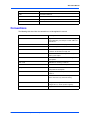
Conventions
The following table describes the conventions used throughout this manual.
Notation
Description
0x00000000
Typical notation for hexadecimal numbers (digits
are 0 through F), for example used for addresses
and offsets
0b0000
Same for binary numbers (digits are 0 and 1)
bold
Used to emphasize a word
Screen
Used for on-screen output and code related
elements or commands in body text
Courier + Bold
Used to characterize user input and to separate it
from system output
Reference
Used for references and for table and figure
descriptions
File > Exit
Notation for selecting a submenu
<text>
Notation for variables and keys
[text]
Notation for software buttons to click on the screen
and parameter description
...
Repeated item for example node 1, node 2, ...,
node 12
.
Omission of information from example/command
that is not necessary at the time being
.
.
..
Ranges, for example: 0..4 means one of the
integers 0,1,2,3, and 4 (used in registers)
|
Logical OR
PMC-CGM Installation and Use (6806800D53C)
11
About this Manual
Notation
Description
Indicates a hazardous situation which, if not
avoided, could result in death or serious injury
Indicates a hazardous situation which, if not
avoided, may result in minor or moderate injury
Indicates a property damage message
No danger encountered. Pay attention to important
information
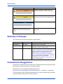
Summary of Changes
This manual has been revised and replaces all prior editions.
Part Number
Publication Date
Description
6806800D53A
June 2007
Development acces draft version
6806800D53B
September 2007
Added content to chapters "Access and Configuration"
and "MIB Description", editorial changes
6806800D53C
March 2008
Updated manual to Emerson style, added section
Configuring the Module on page 28, updated front panel
graphics to include crossed-out telephone receiver,
added section Using a MIB Browser on page 37,
updated section Define SNMP Trap Destinations on
page 38, removed object cgmPathStateT4, added Table
"Input Assignments" on page 48, added
"cgmBootString" object to Table "cgmSys Objects" on
page 58, editorial changes
Comments and Suggestions
We welcome and appreciate your comments on our documentation. We want to know what you
think about our manuals and how we can make them better.
Mail comments to us by filling out the following online form:
http://www.emersonnetworkpowerembeddedcomputing.com/ > Contact Us > Online Form
In "Area of Interest" select "Technical Documentation". Be sure to include the title, part number,
and revision of the manual and tell us how you used it.
12
PMC-CGM Installation and Use (6806800D53C)
Safety Notes
This section provides warnings that precede potentially dangerous procedures
throughout this manual. Instructions contained in the warnings must be followed during
all phases of operation, service, and repair of this equipment. You should also employ
all other safety precautions necessary for the operation of the equipment in your
operating environment. Failure to comply with these precautions or with specific
warnings elsewhere in this manual could result in personal injury or damage to the
equipment.
Emerson intends to provide all necessary information to install and handle the product
in this manual. Because of the complexity of this product and its various uses, we do not
guarantee that the given information is complete. If you need additional information, ask
your Emerson representative.
The product has been designed to meet the standard industrial safety requirements. It
must not be used except in its specific area of office telecommunication industry and
industrial control.
Only personnel trained by Emerson or persons qualified in electronics or electrical
engineering are authorized to install, remove or maintain the product.
The information given in this manual is meant to complete the knowledge of a specialist
and must not be used as replacement for qualified personnel.
Keep away from live circuits inside the equipment. Operating personnel must not
remove equipment covers. Only factory authorized service personnel or other qualified
service personnel may remove equipment covers for internal subassembly or
component replacement or any internal adjustment.
Do not install substitute parts or perform any unauthorized modification of the
equipment or the warranty may be voided. Contact your local Emerson representative
for service and repair to make sure that all safety features are maintained.
Electrical Interference
This equipment has been tested and found to comply with the limits for a Class A digital
device, pursuant to Part 15 of the FCC Rules. These limits are designed to provide
reasonable protection against harmful interference when the equipment is operated in a
commercial environment. This equipment generates, uses, and can radiate radio
frequency energy and, if not installed and used in accordance with the instruction
manual, may cause harmful interference to radio communications.
PMC-CGM Installation and Use (6806800D53C)
13
Safety Notes
Operation of this equipment in a residential area is likely to cause harmful interference
in which case the user will be required to correct the interference at his own expense.
Changes or modifications not expressly approved by Emerson could void the user's
authority to operate the equipment. A proper installation in a compliant system will
maintain the required performance. Use only shielded cables when connecting
peripherals to assure that appropriate radio frequency emissions compliance is
maintained.
Operation
Product Damage
Surface
High humidity and condensation on the product surface causes short circuits.
Do not operate the product outside the specified environmental limits. Make sure the
product is completely dry and there is no moisture on any surface before applying
power.
Overheating and Product Damage
Operating the product without forced air cooling may lead to overheating and thus
damage of the product.
When operating the product, make sure that forced air cooling is available in the shelf.
Installation
Damage of Circuits
Electrostatic discharge and incorrect installation and removal of the product can
damage circuits or shorten their life.
Before touching the product or electronic components, make sure that your are working
in an ESD-safe environment.
Product Damage
Incorrect installation of the product can cause damage of the product.
Only use handles when installing/removing the product to avoid damage/deformation to
the face plate and/or PCB.
Damage to Product/Backplane or System Components
Bent pins or loose components can cause damage to the product, the backplane, or
other system components.
Therefore, carefully inspect the product and the backplane for both pin and component
integrity before installation.
14
PMC-CGM Installation and Use (6806800D53C)
Safety Notes
Emerson and our suppliers take significant steps to ensure there are no bent pins on the
backplane or connector damage to the boards prior to leaving the factory. Bent pins
caused by improper installation or by inserting boards with damaged connectors could
void the Emerson warranty for the backplane or boards.
Configuration Switches
Malfunction of the Product
Switches marked as "Reserved" might carry production-related functions and can cause
the product to malfunction if their setting is changed.
Therefore, do not change settings of switches marked as "reserved".
Damage of the Product
Setting/resetting the switches during operation can cause damage of the product.
Therefore, check and change switch settings before you install the product.
Cabling and Connectors
Product Damage
The RJ-45 connector(s) on the face plate are BITS interfaces. Connecting a telephone to
such a connector may destroy your telephone as well as the product.
Make sure that BITS connectors near your working area are clearly marked as network
connectors. In addition, observe the following safety notes:
z
Verify that the length of an electric cable connected to a BITS bushing does not
exceed 100 m.
z
Make sure the BITS bushing of the system is connected only to Telecommunication
Network Voltage level 1 (TNV-1) circuits.
If in doubt, ask your system administrator.
Environment
Always dispose of used modules, system components and RTMs according to your
country’s legislation and manufacturer’s instructions.
PMC-CGM Installation and Use (6806800D53C)
15
Safety Notes
16
PMC-CGM Installation and Use (6806800D53C)
Sicherheitshinweise
Dieses Kapitel enthält Hinweise, die potentiell gefährlichen Prozeduren innerhalb dieses
Handbuchs vorrangestellt sind. Beachten Sie unbedingt in allen Phasen des Betriebs,
der Wartung und der Reparatur des Systems die Anweisungen, die diesen Hinweisen
enthalten sind. Sie sollten außerdem alle anderen Vorsichtsmaßnahmen treffen, die für
den Betrieb des Produktes innerhalb Ihrer Betriebsumgebung notwendig sind. Wenn Sie
diese Vorsichtsmaßnahmen oder Sicherheitshinweise, die an anderer Stelle diese
Handbuchs enthalten sind, nicht beachten, kann das Verletzungen oder Schäden am
Produkt zur Folge haben.
Emerson ist darauf bedacht, alle notwendigen Informationen zum Einbau und zum
Umgang mit dem Produkt in diesem Handbuch bereit zu stellen. Da es sich jedoch um
ein komplexes Produkt mit vielfältigen Einsatzmöglichkeiten handelt, können wir die
Vollständigkeit der im Handbuch enthaltenen Informationen nicht garantieren. Falls Sie
weitere Informationen benötigen sollten, wenden Sie sich bitte an die für Sie zuständige
Geschäftsstelle von Emerson.
Das System erfüllt die für die Industrie geforderten Sicherheitsvorschriften und darf
ausschließlich für Anwendungen in der Telekommunikationsindustrie und im
Zusammenhang mit Industriesteuerungen verwendet werden.
Einbau, Wartung und Betrieb dürfen nur von durch Emerson ausgebildetem oder im
Bereich Elektronik oder Elektrotechnik qualifiziertem Personal durchgeführt werden.
Die in diesem Handbuch enthaltenen Informationen dienen ausschließlich dazu, das
Wissen von Fachpersonal zu ergänzen, können dieses jedoch nicht ersetzen.
Halten Sie sich von stromführenden Leitungen innerhalb des Produktes fern. Entfernen
Sie auf keinen Fall Abdeckungen am Produkt. Nur werksseitig zugelassenes
Wartungspersonal oder anderweitig qualifiziertes Wartungspersonal darf Abdeckungen
entfernen, um Komponenten zu ersetzen oder andere Anpassungen vorzunehmen.
Installieren Sie keine Ersatzteile oder führen Sie keine unerlaubten Veränderungen am
Produkt durch, sonst verfällt die Garantie. Wenden Sie sich für Wartung oder Reparatur
bitte an die für Sie zuständige Geschäftsstelle von Emerson. So stellen Sie sicher, dass
alle sicherheitsrelevanten Aspekte beachtet werden.
EMV
Das Produkt wurde in einem Emerson Standardsystem getestet. Es erfüllt die für digitale
Geräte der Klasse A gültigen Grenzwerte in einem solchen System gemäß den FCCRichtlinien Abschnitt 15 bzw. EN 55022 Klasse A. Diese Grenzwerte sollen einen
angemessenen Schutz vor Störstrahlung beim Betrieb des Produktes in Gewerbe- sowie
Industriegebieten gewährleisten.
PMC-CGM Installation and Use (6806800D53C)
17
Sicherheitshinweise
Das Produkt arbeitet im Hochfrequenzbereich und erzeugt Störstrahlung. Bei
unsachgemäßem Einbau und anderem als in diesem Handbuch beschriebenen Betrieb
können Störungen im Hochfrequenzbereich auftreten.
Warnung! Dies ist eine Einrichtung der Klasse A. Diese Einrichtung kann im
Wohnbereich Funkstörungen verursachen. In diesem Fall kann vom Betreiber verlangt
werden, angemessene Maßnahmen durchzuführen.
Operation
Beschädigung des Produktes
Hohe Luftfeuchtigkeit und Kondensat auf der Oberfläche des Blades können zu
Kurzschlüssen führen.
Betreiben Sie das Produkt nur innerhalb der angegebenen Grenzwerte für die relative
Luftfeuchtigkeit und Temperatur. Stellen Sie vor dem Einschalten des Stroms sicher,
dass sich auf dem Produkt kein Kondensat befindet.
Überhitzung und Beschädigung des Blades
Betreiben Sie das Blade ohne Zwangsbelüftung, kann das Blade überhitzt und
schließlich beschädigt werden.
Bevor Sie das Blade betreiben, müssen Sie sicher stellen, dass das Shelf über eine
Zwangskühlung verfügt.
Installation
Beschädigung von Schaltkreisen
Elektrostatische Entladung und unsachgemäßer Ein- und Ausbau von Blades kann
Schaltkreise beschädigen oder ihre Lebensdauer verkürzen.
Bevor Sie Blades oder elektronische Komponenten berühren, vergewissern Sie sich,
dass Sie in einem ESD-geschützten Bereich arbeiten.
Beschädigung des Produktes
Fehlerhafte Installation des Produktes kann zu einer Beschädigung des Produktes
führen.
Verwenden Sie die Handles, um das Produkt zu installieren/deinstallieren. Auf diese
Weise vermeiden Sie, dass das Front Panel oder die Platine deformiert oder zerstört
wird.
Beschädigung des Produktes, der Backplane oder von System Komponenten
Verbogene Pins oder lose Komponenten können zu einer Beschädigung des Produktes,
der Backplane oder von Systemkomponenten führen.
Überprüfen Sie daher das Produkt sowie die Backplane vor der Installation sorgältig und
stellen Sie sicher, dass sich beide in einwandfreien Zustand befinden und keine Pins
verbogen sind.
18
PMC-CGM Installation and Use (6806800D53C)
Sicherheitshinweise
Emerson und unsere Zulieferer unternehmen größte Anstrengungen um
sicherzustellen, dass sich Pins und Stecker von Boards vor dem Verlassung der
Produktionsstätte in einwandfreiem Zustand befinden. Verbogene Pins, verursacht
durch fehlerhafte Installation oder durch Installation von Boards mit beschädigten
Steckern kann die durch Emerson gewährte Garantie für Boards und Backplanes
erlöschen lassen.
Schaltereinstellungen
Fehlfunktion des Produktes
Schalter, die mit 'Reserved' gekennzeichnet sind, können mit produktionsrelevanten
Funktionen belegt sein. Das Ändern dieser Schalter kann im normalen Betrieb
Störungen auslösen.
Verstellen Sie nur solche Schalter, die nicht mit 'Reserved' gekennzeichnet sind. Prüfen
und ggf. ändern Sie die Einstellungen der nicht mit 'Reserved' gekennzeichneten
Schalter, bevor Sie das Produkt installieren.
Beschädigung des Produktes
Das Verstellen von Schaltern während des laufenden Betriebes kann zur Beschädigung
des Produktes führen.
Prüfen und ändern Sie die Schaltereinstellungen, bevor Sie das Produkt installieren.
Kabel und Stecker
Beschädigung des Produktes
Die RJ-45-Stecker an der Frontblende sind BITS-Schnittstellen. Der Anschluss eines
Telefones an die RJ-45-Stecker kann sowohl das Telefon als auch das Produkt
zerstören.
Stellen Sie daher sicher, dass BITS-Stecker an Ihrem Arbeitsplatz eindeutig als
Netzwerkstecker gekennzeichnet sind. Beachten Sie ferner die folgenden
Sicherheitsweise:
z
Stellen Sie sicher, dass die Länge eines Kabels, welches an den BITS-Stecker
angeschlossen ist, 100 m nicht überschreitet.
z
Stellen Sie sicher, dass der BITS-Stecker ausschließlich mit einem TNV-1 Stromkreis
verbunden ist.
z
Wenden Sie sich bei Fragen an ihren Systemadministrator.
Umweltschutz
Entsorgen Sie alte Batterien und/oder Blades/Systemkomponenten/RTMs stets gemäß
der in Ihrem Land gültigen Gesetzgebung und den Empfehlungen des Herstellers.
PMC-CGM Installation and Use (6806800D53C)
19
Sicherheitshinweise
20
PMC-CGM Installation and Use (6806800D53C)
Introduction
1.1
1
Features
The Clock Generator Module (PMC-CGM) is a PMC module which is either available together
with the Emerson ATCA-F103 switch or as part of an accessory kit. It can only be used in
conjunction with the ARTM-F103-STX.
The PMC-CGM is delivered with payload software which lets you configure and monitor the
clock synchronization via SNMPv2 and Management Information Bases (MIBs). You may use
the software as an interface to write a higher-level clock manager software.
The PMC-CGM serves the following purposes:
z
Synchronizes to a reference clock (line card clock CLK3, aka. REFA/REFB or external
E1/T1 clock) and provides a system clock (CLK1/CLK2) in an AdvancedTCA chassis and
to up to two extension shelves.
z
Acts as temporary stand-alone clock source if all reference clocks failed while maintaining
clock phase and frequency as long as possible ("holdover mode").
This is accomplished by measuring the reference clock against a high-precision oscillator
and calculating the frequency/phase offset to be applied when the reference clock fails.
The hardware/firmware is designed so that two clock modules form a protection (master/slave)
pair. If the master module fails, the slave module takes over seamlessly without disturbing the
system clocks.
For a PMC-CGM support on the ATCA-F103, the following software versions (or higher) are
required on the ATCA-F103:
z
Application: 4.0.629
z
IPMI firmware: 1.03.082
z
Bootloader: 4.0.629
For more details on the clocking concept used in your system refer to the Centellis CO 31kX
Installation and Use manual.
PMC-CGM Installation and Use (6806800D53C)
21
Introduction
Standard Compliances
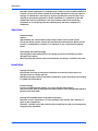
The following graphic shows the PMC-CGM.
Figure 1-1
1.2
PMC-CGM
Standard Compliances
The PMC-CGM, when installed in a compliant chassis, meets the following standards:
Table 1-1 Standard Compliances and Clocking Standards
Standard
Description
UL 60950-1,
Legal safety requirements
EN 60950-1,
IEC 60950-1
CAN/CSA C22.2 No 60950-1
CISPR 22
CISPR 24
Legal EMC requirements on system level
(predefined Emerson system)
EN 55022
EN 55024
FCC Part 15
Industry Canada ICES-003
VCCI Japan
AS/NZS CISPR 22
EN 300 386
NEBS Standard GR-1089 CORE
22
PMC-CGM Installation and Use (6806800D53C)
Ordering Information
Introduction
Table 1-1 Standard Compliances and Clocking Standards (continued)
Standard
Description
G.703
BITS interface
G.813
Clock quality
TR-1244
ANSI/IPC-A610 Rev.C Class 2
Manufacturing requirements
ANSI/IPC-7711
ANSI/IPC-7721
ANSI-J-001...003
NEBS Standard GR-63-CORE
Environmental requirements
ETSI EN 300 019 series
PICMG 3.0 R1.0
Defines mechanics, blade dimensions, power
distribution, power and data connectors, and
system management
The product has been designed to meet the directive on the restriction of the use of
certain hazardous substances in electrical and electronic equipment (RoHS) Directive
2002/95/EC.
1.3
Ordering Information
As of the printing date of this manual, this guide supports the boards model listed below.
Table 1-2 Available Board Variants
Order Number
Description
PMC-CGM2
TELECOM CLOCK GENERATOR MODULE FOR ATCA-F103 (RoHS 6/6)
PMC-CGM Installation and Use (6806800D53C)
23
Introduction
24
Ordering Information
PMC-CGM Installation and Use (6806800D53C)
Hardware Preparation and Installation
2.1
2
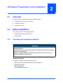
Overview
In this section, you can find information on the following topics:
2.2
z
Things to observe before the installation
z
Installation procedure
z
Available accessories
Before Installation
This section provides the following information:
2.2.1
z
Unpacking and inspecting the module
z
Requirements
Unpacking and Inspecting the Module
Damage of Circuits
Electrostatic discharge and incorrect module installation and removal can damage
circuits or shorten their life.
Before touching the module or electronic components, make sure that you are
working in an ESD-safe environment.
Shipment Inspection
To inspect the shipment, perform the following steps.
1. Verify that you have received all items of your shipment:
Printed user manual
PMC-CGM module
Any optional items ordered
PMC-CGM Installation and Use (6806800D53C)
25
Hardware Preparation and Installation
Requirements
2. Check for damage and report any damage or differences to the customer service.
3. Remove the desiccant bag shipped together with the module and dispose of it
according to your country’s legislation.
The product is thoroughly inspected before shipment. If any damage occurred during
transportation or any items are missing, please contact our customer's service
immediately.
2.2.2
Requirements
Before you power up the module, calculate the power needed according to your system
configuration.
2.2.2.1
Environmental Requirements
You must make sure that the board, when operated in your particular system configuration,
meets the environmental requirements specified below.
Operating temperatures refer to the temperature of the air circulating around the board
and not to the component temperature.
Board Damage
High humidity and condensation on the board surface causes short circuits.
Do not operate the board outside the specified environmental limits. Make sure the
board is completely dry and there is no moisture on any surface before applying
power.
26
PMC-CGM Installation and Use (6806800D53C)
Requirements
Hardware Preparation and Installation
Table 2-1 Environmental Requirements
Feature
Operating
Non-Operating (packed state)
Temperature
+5ºC (+41°F) to +40ºC (+104°F)
(normal operation) according to NEBS
Standard GR-63-CORE
-40ºC (-40°F) to +85ºC (+185°F)
-5°C (+23°F) to +55°C (+131°F)
(exceptional operation) according to
NEBS Standard GR-63-CORE
Temp. change
+/- 0.25ºC/min according to NEBS
Standard GR-63-CORE
+/- 0.25ºC/min
Relative humidity
5% to 90% non-condensing according
to Emerson-internal environmental
requirements
5% to 95% non-condensing according to
Emerson-internal environmental
requirements
Vibration (tested
in target platform)
0.1 g from 5 to 100 Hz and back to 5 Hz
at a rate of 0.1 octave/minute.
5-20 Hz at 0.01 g2/Hz
20-200 Hz at -3.0 dB/octave
Random 5-20 Hz at 1 m2/Sec3
Random 20-200 Hz at -3 dB/octave
Shock
Half-sine, 11 mSec, 30
m/Sec2
Blade level packaging
Half-sine, 6 mSec at 180 m/Sec2
Free fall
-
200 mm/all edges and corners
1.0 m (packaged) per ETSI 300 019-2-2
(Blade level packaging)
100 mm (unpackaged) per GR-63CORE
2.2.2.2
Power Requirements
Make sure that the module is only used on an ATCA-F103 blade in an AdvancedTCA shelf
connected to -48VDC up to -60VDC (rated voltage), according to Telecommunication Network
Voltage (TNV-2).
A TNV-2 circuit is a circuit whose normal operating voltages exceed the limits for a safety-extralow-voltage (SELV) under normal operating conditions, and which is not subject to overvoltages
from telecommunication networks.
Table 2-2 DC Module Power Requirements
Feature
Value
Rated Voltage
3.3V
Operating Voltage
3.3V +/-3%
Input current
1.5A
PMC-CGM power dissipation
5W (max.)
PMC-CGM Installation and Use (6806800D53C)
27
Hardware Preparation and Installation
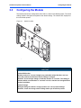
2.3
Configuring the Module
Configuring the Module
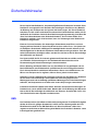
The module provides the configuration switch SW1 as shown in the following figure. The switch
settings shown in the figure correspond to the default settings. The switches are displayed as
the small white squares.
Figure 2-1
Switch Location
Product Malfunction
Switches marked as 'reserved' might carry production-related functions and can
cause the product to malfunction if their setting is changed.
Therefore, do not change settings of switches marked as 'reserved'. The setting of
switches which are not marked as 'reserved' has to be checked and changed before
product installation.
Product Damage
Setting/resetting the switches during operation can cause product damage.
Therefore, check and change switch settings before you install the product.
28
PMC-CGM Installation and Use (6806800D53C)
Installing and Removing the Module
Hardware Preparation and Installation
Table 2-3 Switch Settings
Switch
Description
SW1-1
Reserved (OFF: default value)
SW1-2
Reserved (OFF: default value)
SW1-3
Restores default static IP addresses
OFF: Dynamic IP addresses are assigned by the ATCA-M100, for details
refer to Table "MIB Browser Settings" on page 37 (default)
ON: Static IP addresses are assigned
192.168.21.40: acces via ETHA on ARTM-F103-STX
192.168.22.40: acces via ETHB on ARTM-F103-STX
SW1-4
2.4
Reserved (OFF: default value)
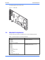
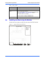
Installing and Removing the Module
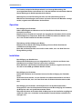
The PMC-CGM can be installed on the PMC slot of the AdvancedTCA ATCA-F103 blade.
Figure 2-2
Location of PMC Slot on ATCA-F103
PMC-CGM Installation and Use (6806800D53C)
29
Hardware Preparation and Installation
Hardware Upgrades and Acessories
Before installing an PMC module observe the following notes.
z
To ensure proper EMC shielding, either operate the blade with the PMC-CGM
module installed or with a blind panel.
z
If the blade is upgraded with a PMC module, ensure that the blind panel is stored in
a safe place in order to be reused again when removing the PMC module.
Installation Procedure
To install the PMC module, proceed as follows:
1. Remove the blind panel from the PMC slot of the ATCA-F103.
2. Store the blind panel in a safe place.
3. Connect the PMC module carefully to the PMC slot.
4. Make sure that standoffs of the PMC module cover the mounting holes of the blade.
5. Place the screws delivered with the PMC module into the mounting holes of the
blade (from the back side of the blade).
6. Fasten screws.
7. Connect interface cables as required - for more information refer to the ARTM-F103STX Installation and Use manual.
Removal Procedure
To remove a PMC module, proceed as follows:
1. Remove interface cables, if applicable.
2. Remove screws from back side of the blade’s PMC slot.
3. Disconnect PMC module carefully from the PMC slot.
4. Install the blind panel.
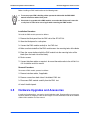
2.5
Hardware Upgrades and Acessories
In multi-shelf configurations, you need a clock distribution cable. Emerson offers an accessory
kit which contains a category 5 cable of 10 m length. For more information refer to the CABLECGM2-CLK Installation and Use manual.
30
PMC-CGM Installation and Use (6806800D53C)
Controls, LEDs and Connectors
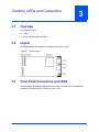
3.1
3
Overview
This chapter describes:
3.2
z
Layout
z
Front panel connectors and LEDs
Layout
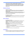
The following figure shows the main components of the PMC-CGM.
Figure 3-1
3.3
Module Layout
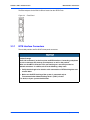
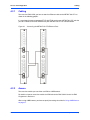
Front Panel Connectors and LEDs
At the front panel of the PMC-CGM, there are the two RJ-45 connectors for the Building
Integrated Timing Source (BITS) interfaces and six LEDs.
PMC-CGM Installation and Use (6806800D53C)
31
Controls, LEDs and Connectors
BITS Interface Connectors
The Ethernet ports for the PMC-CGM are located on the ARTM-F103.
Figure 3-2
3.3.1
Front Panel
BITS Interface Connectors
The module provides two RJ-45 BITS front panel connectors.
Product Damage
The RJ-45 connector(s) on the face plate are BITS interfaces. Connecting a telephone
to such a connector may destroy your telephone as well as the product.
Make sure that BITS connectors near your working area are clearly marked as
network connectors. In addition, observe the following safety notes:
z
Verify that the length of an electric cable connected to a BITS bushing does not
exceed 100 m.
z
Make sure the BITS bushing of the system is connected only to
Telecommunication Network Voltage level 1 (TNV-1) circuits.
If in doubt, ask your system administrator.
32
PMC-CGM Installation and Use (6806800D53C)
LEDs
Controls, LEDs and Connectors
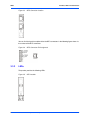
Figure 3-3
BITS Connector Location
You can find the signal description of the the BITS connectors in the following figure where x is
the number of the BITS connector.
Figure 3-4
3.3.2
BITS Connector Pin Assignment
LEDs
The product provides the following LEDs.
Figure 3-5
LED Location
PMC-CGM Installation and Use (6806800D53C)
33
Controls, LEDs and Connectors
LEDs
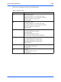
You can find a description of the LEDs in the following table.
Table 3-1 LED Description
Name
Description
B1
BITS Interface 1 Status
Green: BITS interface 1 is in use and status is okay
Orange: BITS interface 1 is in use and status is not okay
Red: : BITS interface 1 is out-of-service
OFF: Not defined
B2
BITS Interface 2 Status
Green: BITS interface 2 is in use and status is okay
Orange: BITS interface 2 is in use and status is not okay
Red: : BITS interface 2 is out-of-service
OFF: Not defined
M/S
Master/Slave Operation
Green: PMC-CGM operates as Master
Amber: Not defined
Yellow: PMC-CGM operates as Slave
OFF: PMC-CGM is non-operational (by application)
Mode
Mode
Green: PMC-CGM operates in locked mode
Amber: PMC-CGM operates in holdover mode
Yellow: PMC-CGM operates in free-run mode
OFF: not defined
OOS
Out-Of-Service
Red: PMC-CGM is out-of-service
Off: Not defined
IS
In Service
Green: PMC-CGM is in service
Off: Not defined
34
PMC-CGM Installation and Use (6806800D53C)
Access and Configuration
4.1
4
Overview
In this chapter, you can find information on the following topics:
4.2
z
How to access the module.
z
What to observe when using a MIB browser.
z
How to configure the module.
Accessing the PMC-CGM
To access the module you have to provide the necessary cabling and then use IPMI or a MIB
browser to access to the module, for details refer to the following sections.
PMC-CGM Installation and Use (6806800D53C)
35
Access and Configuration
4.2.1
Cabling
Cabling
To access the PMC-CGM, you have to attach an Ethernet cable to the ARTM-F103-STX as
shown in the following graphic.
It is mandatory that you connect port ETH7 with ETHA on the same ARTM-F103-STX and that
you cross-connect ETH8 with ETHB on the peer ARTM-F103-STX as indicated below.
Figure 4-1
4.2.2
Connecting the ARTM-F103-STX Ethernet Ports
Access
To access the module you can either use IPMI or a MIB browser.
For details on how to access the module via IPMI refer to the PMC-CGM: Control via IPMI
Programmer’s Reference.
When using a MIB browser, you have to specify the settings described in Using a MIB Browser
on page 37.
36
PMC-CGM Installation and Use (6806800D53C)
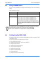
Using a MIB Browser
4.3
Access and Configuration
Using a MIB Browser
When you are using a MIB browser to configure the PMC-CGM, you have to use the following
settings.
Table 4-1 MIB Browser Settings
Setting
Value
Read community
Public
Write community
Public
Dynamic IP addresses
assigned by ATCA-M100
172.17.<SGA>.18: acces via ETHA on left ARTM-F103-STX
172.18.<SGA>.18: acces via ETHB on left ARTM-F103-STX
172.17.<SGA>.28: acces via ETHB on right ARTM-F103-STX
172.18.<SGA>.28: acces via ETHA on right ARTM-F103-STX
The first three octets of the IP addresses correspond to the first three
octets of the shelf manager IP connection record (SMICR) which is part
of the chassis FRU. It can be extracted by the ShM of your system. For
details of the SMICR refer to the PICMG 3.0 Rev. 1.0 AdvancedTCA Base
Specification.
All changes that you apply via the MIB browser are volatile, that means they are lost
when the module is rebooted. The only exception is the cgmBootString
(OID:.1.3.6.1.4.1.3656.8152.1.3.33) object, which is stored in the NVRAM.
4.4
Configuring the PMC-CGM
To configure the PMC-CGM, you can perform the following tasks which are described in detail
in the following sections.
z
Define the IP address of the protection partner module
z
Define SNMP trap destinations
z
Configure the interface mode - SDH/E1 versus SONET/T1
z
Configure the BITS interface
z
Configure the initial master/slave role
z
Setup a multishelf configuration
z
Configure the reference clock
z
Upgrade the firmware/software
z
Reset the PMC-CGM
z
Configure parameters for event handling
PMC-CGM Installation and Use (6806800D53C)
37
Access and Configuration
Define IP Address of the Protection Partner Module
You can perform these tasks independently from each other.
4.4.1
Define IP Address of the Protection Partner Module
The PMC-CGM modules usually work in a master/slave configuration. The protection partner
is the other PMC-CGM module, regardless of the master/slave role. The default partner
address is configured according to the IP address configuration described in Table "MIB
Browser Settings" on page 37.
Defining the IP address of the protection partner module
To define the IP address via the MIB, process as follows:
1. Start SNMP manager or MIB browser.
2. Connect to the PMC-CGM using one of its IP addresses.
3. In object cgmProtectionPartnerAddress OID: .1.3.6.1.4.1.3656.8152.1.1.22.0 set
the IP address of the partner PMC-CGM module.
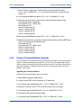
4.4.2
Define SNMP Trap Destinations
The PMC-CGM firmware keeps an event log which captures errors, warnings and informative
messages in a RAM buffer. The event log can always be accessed via SNMP. Additionally, it
is possible to configure the firmware so that each entry up to a certain severity level is posted
as an SNMP trap to a specified destination.
Defining SNMP Trap Destinations
To define SNMP trap destinations, proceed as follows:
1. Start SNMP manager or MIB browser.
2. Connect to the PMC-CGM using one of its IP addresses.
3. Go to object cgmBootString OID:.1.3.6.1.4.1.3656.8152.1.3.33.
4. Enter IP address to which the SNMP traps have to be sent in the h|host|trapDest
parameter.
This setting is stored persitently in the NVRAM of the module and is applied after
the next reboot.
5. Go to object cgmTrapDestination OID: .1.3.6.1.4.1.3656.8152.1.3.32.0.
6. Enter IP address to which the SNMP traps have to be sent.
This setting is only valid until the next reboot. After the reboot, the default IP address
defined via the cgmBootString object is applied.
38
PMC-CGM Installation and Use (6806800D53C)
Configure the Interface Mode
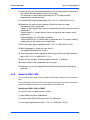
4.4.3
Access and Configuration
Configure the Interface Mode
You can chose between SONET/T1 and SDH/E1 mode via the MIB object cgmInterfaceMode
OID: .1.3.6.1.4.1.3656.8152.1.1.10.0. The modes are used in different regions.
Table 4-2 Interface Modes
Mode Type
MIB Value
Purpose
SONET/T1
0
USA
SDH/E1
1 (default)
Europe/Asia
This entry determines whether an input frequency of 1544KHz (Sonet/T1) or 2048KHz
(SDH/E1) can be selected for the cgmInputFrequency object
(OID:.1.3.6.1.4.1.3656.8152.1.1.1.1.3).
Configuring the interface mode
To configure the interface mode of the PMC-CGM, proceed as follows:
1. Start SNMP manager or MIB browser.
2. Connect to the PMC-CGM using one of its IP addresses.
3. Go to object cgmInterfaceMode OID: .1.3.6.1.4.1.3656.8152.1.1.10.0.
4. Check whether the default value meets your requirements.
Otherwise, change the value as required.
4.4.4
Configure the BITS Interface
The interface mode determines whether the BITS interface operates in E1 (default value) or T1
mode.
Configuring the BITS interface
To set the line type and line code of the BITS interface, proceed as follows:
1. Start SNMP manager or MIB browser.
2. Connect to the PMC-CGM using one of its IP addresses.
3. In cgmBitsTable OID: .1.3.6.1.4.1.3656.8152.1.1.2 go to object dsx1LineCode OID:
.1.3.6.1.4.1.3656.8152.1.1.2.1.5 and select desired line code value.
For details on the available values refer to Table "cgmBitsTable" on page 49.
4. In cgmBitsTable OID: .1.3.6.1.4.1.3656.8152.1.1.2 go to object dsx1LineType OID:
.1.3.6.1.4.1.3656.8152.1.1.2.1.4 and select desired line type value.
For details on the available values refer to Table "cgmBitsTable" on page 49.
PMC-CGM Installation and Use (6806800D53C)
39
Access and Configuration
4.4.5
Configure Initial Master/Slave Role
Configure Initial Master/Slave Role
After the initial configuration, the master/slave roles are handled by the DPLL software that runs
on the processor of the PMC-CGM.
Configuring the initial master/slave roles
To configure the initial master/slave roles, proceed as follows:
1. Start SNMP manager or MIB browser.
2. Connect to the PMC-CGM using one of its IP addresses.
3. Check the master/slave role of the current PMC-CGM module in the
cgmProtectionState object OID:.1.3.6.1.4.1.3656.8152.1.1.19.0.
The following values are possible: 0 (standaloneMaster: Communication with the
partner is not possible and the module is running in master mode.), 1 (slave), 2
(master).
4. Adapt the master/slave role of the current PMC-CGM module, if necessary, in the
cgmProtectionCmd object OID:.1.3.6.1.4.1.3656.8152.1.1.20.0.
The following values are possible:
0 - Attempt to become master. This is only possible if a valid clock input is present.
1 - Give up mastership to the protection partner. This is only possible if the partner
(slave) has a valid input other than MS_SYNC.
5. Check whether the role change was successful in the cgmProtectionState object
OID:.1.3.6.1.4.1.3656.8152.1.1.19.0.
4.4.6
Setup Multi-Shelf Configuration
You have to define the number of extension shelves, up to two extension shelves are possible.
Setting up a multi-shelf configuration
To set up a multi-shelf configuration, proceed as follows:
1. Start SNMP manager or MIB browser.
2. Connect to the PMC-CGM using one of its IP addresses.
3. Go to cgmExtChConnection object OID:.1.3.6.1.4.1.3656.8152.1.4.11.0.
4. Select the properties of the connections to extension chassis 2 and 3.
The following values are possible:
Single Chassis (0) - default value
Chassis 2 in extension mode (1)
Chassis 3 in extension mode (3)
Chassis 2&3 in extension mode (5)
40
PMC-CGM Installation and Use (6806800D53C)
Configure the Reference Clock
4.4.7
Access and Configuration
Configure the Reference Clock
You can define the reference clock source, the frequency and the priority of the reference clock
inputs. For a description of the respective MIB objects refer to Table "cgmInputTable" on page
47.
Reference clock sources are:
z
BITS interface 1 (input 3, frequency automatically configured via interface mode)
z
BITS interface 2 (input 4, frequency automatically configured via interface mode)
z
Linecard reference clcok A (input 7)
z
Linecard reference clock B (input 12)
For the slave, the reference clock is always the Master/Slave synchronization clock. This is
automatically configured.
When you initially assign priorities, we recommend to start with the highest priority input.
Otherwise, the PLL may switch inputs unnecessarily or end up locked on a low-priority input
while a higher priority input is also valid.
If you want to change the selected PLL input by changing the priority, you have to change to
revertive mode first (cgmProtectionRevertiveModeState OID:.1.3.6.1.4.1.3656.8152.1.1.18.0).
Configuring the reference clock source for the T0/T4 path
To configure the reference clock, proceed as follows:
1. Start SNMP manager or MIB browser.
2. Connect to the PMC-CGM using one of its IP addresses.
3. Go to cgmInputFrequency object OID:.1.3.6.1.4.1.3656.8152.1.1.1.1.3.<instance
number which is equal to input number -1>.
4. Select the desired input frequency.
The following values are possible:
0: 8 KHz
1: 1544 KHz / 2048 KHz, depending on E1/T1 operation.
3: 19.44 MHz
5. Go to cgmT0InputPrioritiy object OID:.1.3.6.1.4.1.3656.8152.1.1.1.1.4.<instance
number which is equal to input number -1>.
6. Select the desired input priority.
A priority value from 2 to 15 is used by the T0 PLL to select an input. A lower
numerical value means a higher priority. A value of 0 disables the input, that means
it will not be selected as reference clock. A value of 1 cannot be set as it is used for
the master/slave synchronization clock.
Default value is 0.
This setting is applied to the protection partner as well.
PMC-CGM Installation and Use (6806800D53C)
41
Access and Configuration
Perform Firmware/Software Upgrade
7. For the T4 path, repeat steps 5 and 6 with the cgmT4InputPriority object
OID:.1.3.6.1.4.1.3656.8152.1.1.1.1.5.<instance number which is equal to input
number -1>.
8. Go to cgmInputRefASource object OID:.1.3.6.1.4.1.3656.8152.1.4.16.0.
9. Select the source (chassis) of the primary linecard derived reference clock.
The following values are possible:
local reference A (0) - default value
local reference B (1)
Chassis 2 reference A (2)
Chassis 2 reference B (3)
Chassis 3 reference A (4)
Chassis 3 reference B (5)
10.Go to cgmInputRefBSource object OID:.1.3.6.1.4.1.3656.8152.1.4.18.0.
11.Select the source of the "secondary" linecard derived reference clock (REFB input
to PLL). Not relevant for distributed mode.
local reference A (0)
local reference B (1) - default value
Chassis 2 reference A (2)
Chassis 2 reference B (3)
Chassis 3 reference A (4)
Chassis 3 reference B (5)
4.4.8
Perform Firmware/Software Upgrade
You can upgrade the firmware/software of the PMC-CGM via the MIB. The firmware/software
upgrade is done by downloading an image from a TFTP server and programming it into the
inactive partition of the boot flash (that means not the one which is currently running) which is
split into two partitions of 32MB each. By default, only one of the two partitions (the active
partition) is accessible.
Upgrading the firmware/software
To upgrade the firmware/software, proceed as follows:
1. Start SNMP manager or MIB browser.
2. Connect to the PMC-CGM using one of its IP addresses.
3. Go to object cgmFwUpdateHost OID: .1.3.6.1.4.1.3656.8152.1.3.26.0.
4. Enter the IP address of the TFTP server that contains the new image.
5. Go to object cgmFwUpdateFile OID:.1.3.6.1.4.1.3656.8152.1.3.27.0.
6. Enter the file that contains the new image.
7. Go to object cgmFwUpdateMd5 OID:.1.3.6.1.4.1.3656.8152.1.3.28.0.
42
PMC-CGM Installation and Use (6806800D53C)
Reset the PMC-CGM
Access and Configuration
8. Enter the checksum (hexadecinal format) of the new image which is contained in
the .md5 file delivered together with the new image.
This checksum is verified after downloading the TFTP image and after
programming it into the boot flash.
9. Go to the object cgmFwUpdateOption OID:.1.3.6.1.4.1.3656.8152.1.3.29.0.
10.Select how to handle revision numbers of the old and the new image.
The following values are possible:
"newer" (0): only images with a version number higher than the current one can be
programmed.
"newerOrSame" (1): images with the same or a higher version number can be
programmed.
"allowDowngrade" (2): downgrade is possible.
"noVersionCheck" (3): no version check is performed at all. This allows installing
images which do not contain version information.
11.Go to the object cgmFwUpdateStart OID:.1.3.6.1.4.1.3656.8152.1.3.30.0.
12.Start the upgrade by setting the value start (1).
The upgrade takes about 3-4 minutes.
13.Check the progress of the upgrade by performing a walk on the cgmEventDescr
object OID:.1.3.6.1.4.1.3656.8152.1.3.1.1.6.
14.Wait until the message "Firmware update successful" is displayed.
15.Reset the PMC-CGM to apply/boot the new image.
16.Optionally, you can now upgrade the backup partition as well by repeating this
procedure.
4.4.9
Reset the PMC-CGM
You can reset the PMC-CGM module via IPMI or SNMP, both methods have the same reset
level.
To reset the PMC-CGM via IPMI, the shelf manager issues the IPMI command "Cold Reset".
Graceful Shutdown functionality is not implemented for the PMC-CGM.
Resetting the PMC-CGM via SNMP
To reset the module via SNMP, proceed as follows:
1. Start SNMP manager or MIB browser.
2. Connect to the PMC-CGM using one of its IP addresses.
3. Go to object cgmRestartCmd OID:.1.3.6.1.4.1.3656.8152.1.3.25.0.
PMC-CGM Installation and Use (6806800D53C)
43
Access and Configuration
Configure Parameters for Event Handling
4. Set object to restart (1).
While resetting the PMC-CGM, the clocks driven by the module are in an undefined
state.
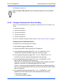
4.4.10
Configure Parameters for Event Handling
You can use the following elements as parameters to define how events are handled in your
system.
z
cgmSysEventLogSize
z
cgmSysEventLogCount
z
cgmSysEventLogClear
z
cgmSysEventLogLevel
z
cgmSysEventTrapLevel
You can find a detailed description of these elements in Table "cgmSys Objects" on page 58.
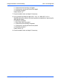
Configuring event handling parameters
To configure the event handling, proceed as follows:
1. Start SNMP manager or MIB browser.
2. Connect to the PMC-CGM using one of its IP addresses.
3. Go to cgmSysEventLogSize object OID:.1.3.6.1.4.1.3656.8152.1.3.10.0.
It contains the maximum number of events the event log can hold.
4. Go to cgmSysEventLogCount object OID:.1.3.6.1.4.1.3656.8152.1.3.11.0.
It contains the current number of events present in the event log.
5. Go to cgmSysEventLogClear object OID:.1.3.6.1.4.1.3656.8152.1.3.12.0.
You can use this element to clear the event log.
When set to 0, events which have not been accessed will be cleared (an event is
marked as "accessed" if its timestamp cgmEventTime is read).
If set to 1, all events are cleared regardless whether they have been accessed or
not. This is not recommended since it may cause events to get lost while the log is
about to be cleared.
6. Go to cgmSysEventLogLevel object OID:.1.3.6.1.4.1.3656.8152.1.3.13.0.
Specifies up to which severity events shall be placed into the event log:
0 - No events are logged
1 - Only critical events are logged
44
PMC-CGM Installation and Use (6806800D53C)
Configure Parameters for Event Handling
Access and Configuration
2 - Critical events and warnings are logged
3 - Critical events, warning and events are logged
4 - Everything is logged
Default value is (3).
7. Check the default value and adapt it if necessary.
8. Go to cgmSysEventTrapLevel object OID:.1.3.6.1.4.1.3656.8152.1.3.14.0.
Specifies up to which severity new event log entries are posted as a trap (using the
cgmLogEvent object).
0 - No events are posted
1 - Only critical events are posted
2 - Critical events and warnings are posted
3 - Critical events, warning and events are posted
4 - Everything is posted
Default value is (3).
9. Check the default value and adapt it if necessary.
PMC-CGM Installation and Use (6806800D53C)
45
Access and Configuration
46
Configure Parameters for Event Handling
PMC-CGM Installation and Use (6806800D53C)
MIB Description
5.1
5
Overview
You can use the CGM-CONTROL-MIB to access and control the clock generator module PMCCGM that is used in your AdvancedTCA system.
It is located at
.iso.org.dod.internet.private.enterprises.forceComputers.cgmControlMIB.motCgm (OID:
.1.3.6.1.4.1.3656.8152.1).
The CGM-CONTROL-MIB contains the following three main branches.
Table 5-1 MIB Structure
5.2
Branch
Used for...
cgmControl
Controlling and configuring the BITS interfaces and the PLL
cgmSys
Maintianing the PMC-CGM (FW/SW upgrade, event log)
cgmClkDist
Distributing clocks in the chassis
cgmControl
The cgmControl branch contains the following information:
z
cgmInputTable - for details refer to Table 5-2 on page 47.
For details on how to use these MIB objects refer to Configure the Reference Clock on page
41.
z
cgmBitsTable - for details refer to Table 5-4 on page 49.
For details on how to use these MIB objects refer to Configure the BITS Interface on page
39.
z
Various MIB objects that are described in Table 5-5 on page 53.
For details on how to use these MIB objects refer to Configure the Interface Mode on page
39, Configure Initial Master/Slave Role on page 40.
The cgmInputTable (OID: .1.3.6.1.4.1.3656.8152.1.1.1) uses the instance number as defined
in Table "Input Assignments" on page 48 as index.
Table 5-2 cgmInputTable
OID
MIB Object
Description
Access
.1.1.1.1.2
cgmInputName
Named source for this input. If the string is
empty the input is not connected.
r
PMC-CGM Installation and Use (6806800D53C)
47
MIB Description
cgmControl
Table 5-2 cgmInputTable (continued)
OID
MIB Object
Description
Access
.1.1.1.1.3
cgmInputFrequency
Configures the input frequency:
r/w
0: 8 KHz
1: 1544 KHz / 2048 KHz, depending on E1/T1
operation.
3: 19.44 MHz
.1.1.1.1.4
cgmT0InputPriority
This setting is applied to the protection partner
as well.
r/w
A priority value from 2 to 15 used by the T0 PLL
to select an input. A lower numerical value
means a higher priority. A value of 0 disables
the input, that means it will not be selected as
reference clock. A value of 1 cannot be set as
it is used for the master/slave synchronization
clock.
Default value is 0.
.1.1.1.1.5
cgmT4InputPriority
Priority of frequency monitor (T4 Path). Lower
numerical values represent a higher priority
than greater values.
r/w
A value of 0 means that the input will never be
selected as active input.
Default value is 0.
.1.1.1.1.6
cgmInputState
Indicates whether the input receives a valid
clock or not.
r/w
.1.1.1.1.7
cgmInputActivityMonitorEna
Controls whether the activity monitor for this
input is enabled.
r/w
.1.1.1.1.8
cgmInputActivityMonitorState
Reports the state of the activity monitor for this
input.
r
Table 5-3 Input Assignments
48
Instance
cgmInputNumber
cgmInputName
Default
cgmInputFrequency
2
3
BITS1
freqE1T1 (1)
3
4
BITS2
freqE1T1 (1)
6
7
REFA
freq8K (0)
10
11
MS_SYNC
freq8K (0)
11
12
REFB
freq8K (0)
PMC-CGM Installation and Use (6806800D53C)
cgmControl
MIB Description
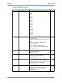
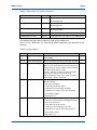
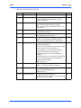
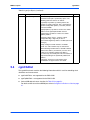
The cgmBitsTable (OID: .1.3.6.1.4.1.3656.8152.1.1.2) uses bitsInterfaceNumber as index.
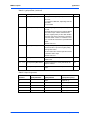
Table 5-4 cgmBitsTable
OID
MIB Object
Description
Access
.1.1.2.1.1
bitsInterfaceNumber
0 for BITS interface 1
r
1 for BITS interface 2
.1.1.2.1.2
bitsEnable
Enables (0) or disables (1) a BITS interface.
Enabling the interface also applies various default
parameters, depending on the operation mode
defined in <cgmInterfaceMode>:
r/w
E1/SDH Mode:
- <dsx1LineType> is <dsx1E1>
- <dsx1LineCode> is <dsx1HDB3>
-< bitsLiuE1Lbo> is <o120>
T1/Sonet Mode:
- <dsx1LineType> is <dsx1D4>
- <dsx1LineCode> is <dsx1B8ZS>
- <bitsLiuT1Lbo> is <ft0to133>
Default value is enabled (0).
.1.1.2.1.3
bitsTxEnable
Enables/disables the line interface transmitter.
r/w
Default value is enabled (1).
.1.1.2.1.4
dsx1LineType
Line type configuration. The allowed settings
depend on the module’s interface mode:
r/w
Applicable for E1:
- dsx1E1 (value 4, default)
- dsx1E1CRCMF (value 7)
- dsx1E1G703 (value 12)
- dsx1E1UnframedAll1 (value 9) (Setting this line
type is equivalent to Transmit AIS in E1 mode.)
- dsx1E1UnframedAlt (value 11, 0101… pattern)
Applicable for T1:
- dsx1D4 (value 3, default)
- dsx1ESF (value 2)
- dsx1UnframedAll1 (value 8)
- dsx1UnframedAlt (value 10, 0101.. pattern)
.1.1.2.1.5
dsx1LineCode
E1/T1 Line code.
r/w
Applicable for E1:
- dsx1HDB3 (default)
- dsx1AMI
Applicable for T1:
- dsx1B8ZS (default)
- dsx1AMI
PMC-CGM Installation and Use (6806800D53C)
49
MIB Description
cgmControl
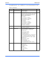
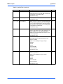
Table 5-4 cgmBitsTable (continued)
OID
MIB Object
Description
Access
.1.1.2.1.6
dsx1LoopbackConfig
Loopback mode
r/w
Loopback mode disabled (1)
local (payload) loopback - Tx to Rx (2)
line loopback - Rx to Tx (3)
Default value is disabled (1).
.1.1.2.1.7
dsx1LineStatus
Current line status. This is a bit mask encoding the
following states:
r
-Bit 0 (value 0x01): Yellow alarm condition
-Bit 3 (value 0x08): Alarm condition
-Bit 5 (value 0x20): Loss of Frame condition
-Bit 6 (value 0x40): Loss of Signal condition
.1.1.2.1.10
bitsCurSsm
The last received synchronization status message
r
Not yet supported
.1.1.2.1.11
bitsSsmE1SaSelect
Selects on which Sa bit the E1 synchronization
status message is expected.
r/w
Default value is (4).
Not yet supported
.1.1.2.1.13
bitsLiuJaEn
Enable jitter attenuator
r/w
Default value is disabled (0).
.1.1.2.1.14
bitsLiuJaDs
Jitter attenuator depth (32 or 128 bits)
r/w
Default value is 128 bits (0).
.1.1.2.1.16
bitsLiuEgl
Receive equalizer gain limit for T1 (-36/-15dB) and
E1 (-43/-12dB)
r/w
Default value is (0).
.1.1.2.1.18
bitsLiuE1Lbo
E1 line build-out select in Ohm (without and with
high return loss)
r/w
120 Ohm (1)
120 Ohm with high return loss (3)
Default value is (1).
.1.1.2.1.19
bitsLiuT1Lbo
T1 line build-out select for DSX-1 application in
feet.
r/w
0 to 133 ft (0)
133 to 266 (1)
266 to 399 (2)
399 to 533 (3)
533 to 655 (4)
Default value is (0).
50
PMC-CGM Installation and Use (6806800D53C)
cgmControl
MIB Description
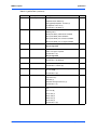
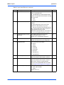
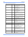
Table 5-4 cgmBitsTable (continued)
OID
MIB Object
Description
Access
.1.1.2.1.35
bitsLiuRxLevel
Receive level in dB
r
2.5 (0)
5.0 (1)
7.5 (2)
10.0 (3)
12.5 (4)
15.0 (5)
17.5 (6)
20.0 (7)
22.5 (8)
25.0 (9)
27.5 (10)
30.0 (11)
32.5 (12)
35.0 (13)
37.5 (14)
40.0 (15)
.1.1.2.1.63
bitsT1RxSync
Resynchronization criteria.
r/w
In D4 framing mode:
- opt1 (0): search for Ft pattern, then search for Fs
pattern
opt2 (1): cross couple Ft and Fs pattern
In ESF Framing mode:
opt1 (0): search for FPS pattern only
opt2 (1): search for FPS and verify with CRC6.
Default value is (0).
.1.1.2.1.69
bitsT1TxYel
Setting this object to on (1), causes the yellow
alarm to be transmitted.
r/w
Default value is (0).
.1.1.2.1.73
bitsT1TxB7zs
Transmit-side bit 7 zero-suppression enable (bit 7
forced to a 1 in channels with all 0s)
r/w
Default value is (0).
.1.1.2.1.75
bitsT1TxFbCT1
Causes the next three consecutive Ft (D4 framing
mode) or FPS (ESF framing mode) bits to be
corrupted causing the remote end to experience a
loss of frame (loss of synchronization)
r/w
Default value is (0).
.1.1.2.1.80
bitsT1TaisCi
Transmit AIS-CI
r/w
Setting this causes the AIS-CI code to be
transmitted, as defined in ANSI T1.403
Default value is (0).
PMC-CGM Installation and Use (6806800D53C)
51
MIB Description
cgmControl
Table 5-4 cgmBitsTable (continued)
OID
MIB Object
Description
Access
.1.1.2.1.81
bitsT1TraiCi
Transmit RAI-CI
r/w
Setting this bit causes the ESF RAI-CI code to be
transmitted in the FDL bit position.
Default value is (0).
.1.1.2.1.91
bitsE1RxSyncC
Frame resynchronization criteria
r/w
Default value is (0).
.1.1.2.1.112
bitsT3ClkForce
When set to (1), it, forces the T3 clock output from
the framer to be output to the PLL even if no signal
is present. This should only be set for test purposes
since the framer will generate a free-running clock
in the absence of a valid input.
r/w
Default value is (0).
.1.1.2.1.113
bitsT3ClkSquelch
When set to disabled (1), it forces the T3 output to
the PLL to be active even if a loss of frame or an
alarm condition exists. This would typically be
disabled for normal operation and only be set for
unframed operation.
r/w
Default value is (0).
.1.1.2.1.114
bitsTestPattern
An 8- or 16-bit test pattern that will be serialized and
repeatedly output on T1E1 port when the test
output is enabled.
r/w
Applies to the following line-type settings:
dsx1ESF
dsx1D4
dsx1E1
dsx1E1CRCMF
dsx1E1unframed
Default value is (0).
.1.1.2.1.115
bitsTestPatternLength
Determines whether a 8 bit (0) or 16 bit (1) test
pattern is generated.
r/w
Applies to the following line-type settings:
dsx1ESF
dsx1D4
dsx1E1
dsx1E1CRCMF
dsx1E1unframed
Default value is (0).
52
PMC-CGM Installation and Use (6806800D53C)
cgmControl
MIB Description
Table 5-4 cgmBitsTable (continued)
OID
MIB Object
Description
Access
.1.1.2.1.116
bitsTestPatternType
Determines the type of the generated test pattern.
r/w
fixed(0) to use a pattern as defined in
bitsTestPattern / bitsTestPatternLength.
prbs11 (1)
prbs15 (2)
qrss20 (3)
Default value is (1).
Applies to the following line-type settings:
dsx1ESF
dsx1D4
dsx1E1
dsx1E1CRCMF
dsx1E1unframed
The following table describes the elements of the cgmControl MIB branch
(OID:.1.3.6.1.4.1.3656.8152.1.1).
Table 5-5 cgmControl Elements
OID
MIB Object
Description
Access
.1.1.10
cgmInterfaceMode
Defines Sonet/T1 (0) or SDH/E1 (1) operation
mode for both BITS interfaces. Affects whether
an input frequency of 1544KHz (Sonet/T1) or
2048KHz (SDH/E1) can be selected for the
cgmInputFrequency object.
r/w
Default value is (1).
.1.1.15
cgmMasterSlaveShelfCombin
ation
Defines whether the master/slave combination is
on the same shelf (0) or on different shelves (1).
r/w
Note: only "same shelf" is supported.
Default value is (0).
.1.1.16
cgmMasterSlaveSync
Defines the communication path to the protection
partner.
r/w
Default value is backplane (0).
.1.1.18
cgmProtectionRevertiveMode
State
When a clock module is in revertive operation
(0), it will always choose the highest priority valid
input.
r/w
When in nonrevertive operation (1), a selected
input will remain selected until it fails. The highest
priority valid input will be chosen at that point and
remain selected until it fails as well.
Default value is (1).
PMC-CGM Installation and Use (6806800D53C)
53
MIB Description
cgmControl
Table 5-5 cgmControl Elements (continued)
OID
MIB Object
Description
Access
.1.1.19
cgmProtectionState
Indicates whether this module is the master or
slave of a protection pair:
r
0 - standaloneMaster: Communication with the
partner is not possible and the module is running
in master mode.
1 - slave
2 - master
.1.1.20
cgmProtectionCmd
Can be used to manually change the state of the
module.
r/w
0 - Attempt to become master. This is only
possible if a valid clock input is present.
1 - Give up mastership to the protection partner.
This is only possible if the partner (slave) has a
valid input other than MS_SYNC.
Whether the operation failed or succeeded can
be seen in the cgmProtectionState element.
.1.1.21
cgmProtectionMasterToSlave
TrackDelay
The tracking delay for the master/slave
synchronization signal in ns units.
r/w
Default value is automatically configured.
.1.1.22
cgmProtectionPartnerAddress
The IP address of the protection partner.
r/w
Default value depends on your configuration.
.1.1.30
cgmPathStateT0
The current state of the T0 PLL:
r
0 - freerun
1 - locked
2 - holdover
3 - preLocked
4 - preLocked2
5 - phaseLost
6 - forcedFreerun
7 - forcedHoldover
.1.1.32
cgmPathInputT0
The input currently selected for the T0 PLL. The
value 255 indicates that no input is selected.
r
.1.1.34
cgmPathInputT4
The input currently selected for the T4 PLL. The
value 255 indicates that no input is selected.
r
Other values reflect the cgmInputNumber
element in the cgmInputTable table, for details
refer to Table "Input Assignments" on page 48.
.1.1.40
cgmCLK1OutputFrequency
The output frequency of CLK1:
r/w
0 - CLK1 output disabled
1 - 8 KHz
Default value is (1).
54
PMC-CGM Installation and Use (6806800D53C)
cgmSys
MIB Description
Table 5-5 cgmControl Elements (continued)
OID
MIB Object
Description
Access
.1.1.41
cgmCLK2OutputFrequency
The output frequency of CLK2:
r/w
0 - CLK2 output disabled
1 - 19.44 MHz
Default value is (1).
.1.1.42
cgmCLK3OutputFrequency
Not supported on PMC-CGM
r/w
.1.1.43
cgmCLK1OutputFramePulse
The output frame pulse of the T1 clock:
r/w
0 - Not inverted, not pulsed
1 - Not inverted, pulsed
2 - Inverted, not pulsed
3 - Inverted, pulsed
Default value is (0).
.1.1.44
cgmT4ClkSquelch
When set to 0 (enable) the output of the T4 PLL
is squelched if no valid input is selected.
If set to 1 (disable) an output is provided in any
case.
5.3
cgmSys
The cgmSys branch contains the following information:
z
cgmEventTable - for details refer to Table 5-6 on page 55.
z
Various MIB objects that are described in Table 5-8 on page 58.
For a description on how to use these objects refer to Configure Parameters for Event
Handling on page 44, Perform Firmware/Software Upgrade on page 42.
The cgmEventTable (OID:.1.3.6.1.4.1.3656.8152.1.3.1) uses cgmEventNumber as index. The
elements of the trap definiton cgmLogEvent (OID:.1.3.6.1.4.1.3656.8152.1.2.0.1) is identical to
the elements defined in cgmEventTable.
Table 5-6 cgmEventTable
OID
MIB Object
Description
Access
.1.3.1.1.2
cgmEventTime
System time stamp when event occurred (this is the
module's run-time since power-up).
r
.1.3.1.1.3
cgmEventSeverity
The event's severity level
r
1. Critical (0): An error has occurred which needs
immediate attention.
2. Warnings (1): An error has occurred which may affect
board operation but does not require immediate attention.
3. Events (2): An event occurred in a board subsystem
which may need attention (e.g. the PLL gained lock).
4. Information (3): Various information messages helpful
for troubleshooting or monitoring the state of the CGM
module.
PMC-CGM Installation and Use (6806800D53C)
55
MIB Description
cgmSys
Table 5-6 cgmEventTable (continued)
OID
MIB Object
Description
Access
.1.3.1.1.4
cgmEventCode
A pre-defined event code - for details refer to Table 5-7 on
page 56.
r
.1.3.1.1.5
cgmEventData
Event specific data
r
.1.3.1.1.6
cgmEventDescr
Textual event description
r
The following table lists all event codes and their severity. Events which cause the module to
give up mastership are marked with an asterisk in the "severity" column.
Table 5-7 Event Codes and Severity
Code
Severity
Description
inputChanged (1)
Event
The selected PLL input has changed.
lostLock (2)
Event
The T0 PLL lost lock and enters holdover mode.
gainedLock (3)
Event
The PLL gained lock.
nowMaster (4)
Event
The module has acquired mastership.
nowSlave (5)
Event
The module has entered slave mode.
validInputsChanged (6)
Event
The validity or more of the PLL inputs has changed .
selectedInputFailed (7)
Event
The selected clock input has failed.
dpllInitError (10)
Warning
Error while initializing the DPLL.
freqValidationError( 11)
Warning
One of the clock sources measured in the FPGA is out
of range.
inputStateChange (12)
Event
Reported when a state change is detected by the
activity monitor.
EventData: Upper 16 bits encode the new state, lower
16 bits encode the input number.
State can be
0 (working)
1 (failing)
2 (failed)
3 (recovering)
4 (unknown)
This is the same information as presented in the
cgmInputActivityMonitor element.
lineCardClkError (20)
Warning
Not applicable for PMC-CGM.
lineCardClkSelected (21)
Event
Not applicable for PMC-CGM.
bitsRlof/c (30/34)
Event
"Loss of frame" / "Loss of frame cleared" event
detected on a BITS interface.
EventData: The BITS interface on which the event has
been detected (0 or 1).
56
PMC-CGM Installation and Use (6806800D53C)
cgmSys
MIB Description
Table 5-7 Event Codes and Severity (continued)
Code
Severity
Description
bitsRlos/c (31/35)
Event
"Loss of signal" / "loss of signal cleared" event
detected on a BITS interface.
EventData: The BITS interface on which the event has
been detected (0 or 1).
bitsRais/c (32/36)
Event
"Alarm indication" / "Alarm indication cleared" event
detected on a BITS interface.
EventData: The BITS interface on which the event has
been detected (0 or 1).
bitsRyel/c (33/37)
Event
"Yellow alarm" / "Yellow alarm cleared" event
detected on a BITS interface.
EventData: The BITS interface on which the event has
been detected (0 or 1).
bitsRxSsmChange (38)
Event
A new synchronization status message has been
received.
EventData: The new SSM message received.
memoryLeak (100)
*Warning
The task checker has detected that the amount of
available memory has dropped below the critical
threshold.
memAllocError (101)
*Warning
Required memory could not be allocated.
EventData: The amount of memory which was
attempted to be allocated.
tftpError( 102)
Event
A TFTP error occurred (firmware update).
firmwareUpdateFailedNc (103)
Warning
The firmware update failed before accessing the boot
flash device.
firmwareUpdateFailedC (104)
*Critical
The firmware update failed possible corruption of the
boot flash device.
The standby boot flash image has not been made
active.
firmwareUpdateSuccess( 105)
Event
The firmware update completed successfully.
firmwareUpdateProgress (106)
Event
A firmware update progress message.
abnormalReset( 110)
Warning
The last reset resulted from a fatal error condition
(checkstop or watchdog).
EventData: A bit mask with the following values:
0x10000000: Indicates watchdog reset
0x08000000: Indicates checkstop reset
linkFailure (120)
Warning
The active network connection failed, the firmware
switched to the inactive link.
EventData: either 0 or 1, indicating the link which
failed.
linkSwitch (121)
Event
The active network link was switched.
EventData: The new active link (0 or 1)
info (200)
Info
General system information.
For debugging only.
PMC-CGM Installation and Use (6806800D53C)
57
MIB Description
cgmSys
Table 5-7 Event Codes and Severity (continued)
Code
Severity
Description
genSysError (1000)
Warning
A general system error.
For debugging only.
genSysErrorC (1001)
*Critical
A general critical system error.
For debugging only.
startupComplete (130)
Event
Indicates that the clock module has started and is
ready for operation.
resetRequest (131)
Event
Indication that the module is being resetted.
invalidBootOptions (140)
Warning
Invalid parameters were given for the cgmBootString.
The following table describes the elements of the cgmSys MIB branch
(OID:.1.3.6.1.4.1.3656.8152.1.3). They provide general control and status operations for the
event log.
Table 5-8 cgmSys Objects
OID
MIB Object
Description
Access
.1.3.10
cgmSysEventLogSize
The maximum number of events the event log can hold
(about 80000).
r
.1.3.11
cgmSysEventLogCount
The current number of events present in the event log.
r
.1.3.12
cgmSysEventLogClear
Clears the event log.
r/w
When set to 0, events which have not been accessed
will be cleared (an event is marked as "accessed" if its
timestamp cgmEventTime is read).
If set to 1, all events are cleared regardless whether
they have been accessed or not. This is not
recommended since it may cause events to get lost
while the log is about to be cleared.
.1.3.13
cgmSysEventLogLevel
Specifies up to which severity events shall be placed
into the event log:
r/w
0 - No events are logged
1 - Only critical events are logged
2 - Critical events and warnings are logged
3 - Critical events, warning and events are logged
4 - Everything is logged
Default value is (3).
.1.3.14
cgmSysEventTrapLevel
Specifies up to which severity new event log entries
are posted as a trap (using the cgmLogEvent object).
r/w
0 - No events are posted
1 - Only critical events are posted
2 - Critical events and warnings are posted
3 - Critical events, warning and events are posted
4 - Everything is posted
Default value is (3).
58
PMC-CGM Installation and Use (6806800D53C)
cgmSys
MIB Description
Table 5-8 cgmSys Objects (continued)
OID
MIB Object
Description
Access
.1.3.23
cgmSysHwVersion
The hardware revision of the PMC-CGM.
r
.1.3.24
cgmSysSwVersion
The firmware revision of the board in the format "x.y.z"
which corresponds to "<major revision>.<minor
revision>.<build count>.
r
.1.3.25
cgmRestartCmd
Restarts the module when set to 1. The operation is
ignored while a firmware update is ongoing.
r/w
After a successful firmware update this will start the
new firmware.
.1.3.26
cgmFwUpdateHost
The IP address of the TFTP server where the new
firmware image is located.
r/w
.1.3.27
cgmFwUpdateFile
The name of the firmware update image to be
downloaded from the TFTP server.
r/w
.1.3.28
cgmFwUpdateMd5
The MD5 checksum of the firmware image. This
checksum is verified after downloading the TFTP
image and after programming it into the boot flash.
r/w
.1.3.29
cgmFwUpdateOption
Controls how to handle revision numbers of the old and
the new firmware image:
r/w
If "newer" (0) only images with a version number higher
than the current one can be programmed.
If "newerOrSame" (1), images with the same or a
higher version number can be programmed.
If "allowDowngrade" (2), firmware downgrade is
possible.
If "noVersionCheck" (3), no version check is performed
at all. This allows installing images which do not
contain version information.
Default value is (0).
.1.3.30
cgmFwUpdateStart
A value of 1 initiates the firmware update. The value
remains 1 as long as the update is ongoing.
r/w
.1.3.31
cgmSysTelnetEnable
Enables(1) / disables (0) a telnet server on the module.
r/w
Used only for debugging purposes.
Default value is (1).
.1.3.32
cgmTrapDestination
IP address where to send traps to.
r/w
Default value is the host address specified in the boot
parameters of the PMC-CGM.
PMC-CGM Installation and Use (6806800D53C)
59
MIB Description
cgmClkDist
Table 5-8 cgmSys Objects (continued)
OID
MIB Object
Description
Access
.1.3.33
cgmBootString
The boot configuration data consists of a list of
parameter=value pairs separated by spaces. The
following parameters/values are defined:
r/w
(e|ethaddr)=<ip-address>[:netmask] Defines the
module’s IP address/netmask. This is overwritten by
dynamic configuration options (see below). Default
netmask is ffffff00.
(h|host|trapDest)=<ip-address> Defines the default
address for the cgmTrapDestination element.
(g|gatewayip)=<ip-address> Defines the default
gateway address.
(m|mode)=<flag>[,<flag>[,...]] Defines various
configuration flags. <flag> may be one of
-ipmi: Obtain IP/gateway address via IPMI (from shelf
manager).
-dhcp: Configure network interfaces via DHCP.
-static: Use static network setup as defined here.
When obtaining network address via IPMI or DHCP,
and the host address (h=statement) is on the same
subnet as the statically configured IP address
(e=statement), the network part of the host address is
adjusted according to the dynamically obtained IP
address.
Setting this element has no immediate effect,
modifications are applied at the next reboot.
5.4
cgmClkDist
The cgmClkDist branch contains the following information which is used for controlling clock
distribution and measurement:
60
z
cgmDmClkTable - not supported for the PMC-CGM.
z
cgmFrqMonTable - not supported for the PMC-CGM.
z
Various MIB objects that are described in Table 5-5 on page 53.
For details on how to use these MIB objects refer to Configure the Reference Clock on page
41.
PMC-CGM Installation and Use (6806800D53C)
cgmClkDist
MIB Description
The following table describes the elements of the cgmClkDist MIB branch
(OID:.1.3.6.1.4.1.3656.8152.1.4).
Table 5-9 cgmClkDist Objects
OID
MIB Object
Description
Access
.1.4.10
cgmClkDistMode
The clock distribution mode of the module.
r/w
There are four main modes a module can be
operated in:
z
Distributed Mode (0)
For each clock domain (CLK1/2/3), the
module selects a payload card in the shelf
and replicates it to the other payload cards.
The selection can be done manually or
automatically.
Not applicable for PMC-CGM.
z
Extension Mode (1)
The module receives CLK1/2 from the main
shelf and distributes them to the local
payloads. Reference clocks (CLK3) can be
routed to the main shelf.
Not applicable for PMC-CGM.
z
Buffer Mode (2)
The module receives CLK1/2/3 from the
main shelf and distributes them to the local
payloads.
Not applicable for PMC-CGM.
z
Centralized Mode (3)
The module generates the T0 clocks based
on internal or external references. In
centralized mode there may be up to two
shelves connected, operating in either
extension or distribution mode.
z
Extended Centralized Mode (4)
Like centralized mode, except that CLK3 is
routed to the main shelf via the front-panel
connector (i.e. REF A/B can not be selected
as input).
Not applicable for PMC-CGM.
Default value is centralized mode (3).
.1.4.11
cgmExtChConnection
In centralized mode, selects the properties of the
connections to extension chassis 2 and 3 (not
connected, extended mode or buffered mode):
r/w
Single Chassis (0)
Chassis 2 in extension mode (1)
Chassis 3 in extension mode (3)
Chassis 2 and 3 in extension mode (5)
Default value is (0).
PMC-CGM Installation and Use (6806800D53C)
61
MIB Description
cgmClkDist
Table 5-9 cgmClkDist Objects (continued)
OID
MIB Object
Description
Access
.1.4.16
cgmInputRefASource
Determines the source of the "primary" linecard
derived reference clock (REFA input to PLL).
r/w
local reference A (0)
local reference B (1)
Chassis 2 reference A (2)
Chassis 2 reference B (3)
Chassis 3 reference A (4)
Chassis 3 reference B (5)
Default value is (0).
.1.4.17
cgmInputRefASourceLinecard
Determines the source (linecard) of the primary
linecard derived reference clock.
r/w
Not applicable for PMC-CGM.
.1.4.18
cgmInputRefBSource
Determines the source of the "secondary"
linecard derived reference clock (REFB input to
PLL).
r/w
local reference A (0)
local reference B (1)
Chassis 2 reference A (2)
Chassis 2 reference B (3)
Chassis 3 reference A (4)
Chassis 3 reference B (5)
Default value is (1).
.1.4.19
cgmInputRefBSourceLinecard
Determines the source (linecard) of the
secondary linecard derived reference clock.
r/w
Not applicable for PMC-CGM.
62
PMC-CGM Installation and Use (6806800D53C)
A
Related Documentation
A.1
A
Emerson Network Power - Embedded Computing
Documents
The Emerson Network Power - Embedded Computing publications listed below are referenced
in this manual. You can obtain electronic copies of Emerson Network Power - Embedded
Computing publications by contacting your local Emerson sales office. For documentation of
final released (GA) products, you can also visit the following website:
http://www.emersonnetworkpowerembeddedcomputing.com > Resource Center > Technical
Documentation Search. This site provides the most up-to-date copies of Emerson Network
Power - Embedded Computing product documentation.
Table A-1 Emerson Network Power - Embedded Computing Publications
A.2
Document Title
Publication Number
Centellis CO 31kX Installation and Use
6806800A99
ATCA-F103 Installation and Use
6806800D97
ARTM-F103-STX Installation and Use
6806800D79
PMC-CGM: Control via IPMI Programmer’s Reference
6806800D54
CABLE-CGM2-CLK Installation and Use
6806800F47
Related Specifications
For additional information, refer to the following table for related specifications. As an additional
help, a source for the listed document is provided. Please note that, while these sources have
been verified, the information is subject to change without notice.
Company/Org.
Documents
PICMG
PICMG 3.0 AdvancedTCA Base Specification
can be ordered via www.picmg.org
PMC-CGM Installation and Use (6806800D53C)
63
Related Documentation
64
Related Specifications
PMC-CGM Installation and Use (6806800D53C)
Index
A
I
Abbreviations 9
Access 35
Cabling 36
IP addresses 37
Via IPMI 36
Via MIB browser 37
ATCA-F103 21
PMC slot on 29
PMC-CGM support on 21
Interface mode
Configuration 39
MIB objects 53
IP addresses 29
Dynamic 29, 37
Static 29
B
BITS interface 32
Configuration 39
Connector 33
LEDs 34
MIB objects 49
Blind panel 30
C
Clock distribution cable 30
Clocking concept 21
Clocking standards 22
Compliances 22
Contact information 12
Content overview 9
Conventions 11
E
E1 39
Environmental requirements 27
Event codes 56
Event handling 44
MIB objects 58
Procedure 44
F
Features 21
Feedback 12
Firmware upgrade
MIB objects 58
Procedure 42
Free-run mode 34
Front panel 32
BITS interface 32
LEDs 33
H
Holdover mode 34
PMC-CGM Installation and Use (6806800D53C)
L
LEDs 33
List of abbreviations 9
Locked mode 34
M
Master/slave 21, 40
Configuration 40
LED 34
MIB objects 53
MIB 47
MIB browser 37
Changes 37
Read community 37
Write community 37
Module layout 31
Multi-shelf support 40
Configuration 40
O
Operating modes 34
Free-run 34
Holdover 34
Locked 34
Operating temperature 27
Order numbers 23
P
PMC slot on ATCA-F103 29
PMC-CGM support 21
Power requirements 27
Procedures
Configuring BITS interface 39
Configuring event handling 44
Configuring master/slave role 40
Configuring multi-shelf support 40
Configuring the reference clock 41
Defining interface mode 39
Defining IP address of protection partner 38
Defining SNMP trap destinations 38
Installing the module 30
Removing the module 30
Resetting the PMC-CGM 43
65
Unpacking the module 25
Upgrading the firmware 42
Protection partner 21, 38
R
Reference clock 41
Configuration 41
MIB objects 47, 61
Requirements 26
Environmental 27
Power 27
Reset 43
Via IPMI 43
Via SNMP 43
66
RoHS 23
S
Safety notes 13
SDH 39
SONET 39
Standard compliances 22
SW1 28
Switch settings 28
T
T1 39
TNV-2 27
Trap destinations 38
PMC-CGM Installation and Use (6806800D53C)