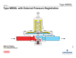
1
Bulletin 71.1:MR95
December 2014
MR95 Series Industrial Pressure Regulators
P1757
TYPE MR95L
P1753
TYPE MR95H
PRESSURE REDUCING REGULATORS
D103742X012
Figure 1. Typical MR95 Series Industrial Pressure Regulators
www.fisherregulators.com
Bulletin 71.1:MR95
Specifications
This section lists the specifications for the MR95 Series regulators. Factory specification such as type, maximum inlet
pressure, maximum temperature, maximum outlet pressure, spring range, orifice size and seat material are stamped on the
nameplate fastened on the regulator at the factory.
Available Constructions
Type MR95L: Low-pressure regulator for 2 to 30 psig /
0.14 to 2.1 bar outlet pressures
Type MR95H: High-pressure regulator for 5 to
150 psig / 0.34 to 10.3 bar outlet pressures
Type MR95HP: High-pressure regulator for 15 to
400 psig / 1.0 to 27.6 bar outlet pressures (soft-seated)
Type MR95HT: High-pressure/high-temperature
regulator for 15 to 300 psig / 1.0 to 20.7 bar outlet
pressures (metal seat) and up to 650°F / 343°C
Type MR95LD: Low-pressure differential regulator for
2 to 30 psi / 0.14 to 2.1 bar differential pressures with
handwheel and packing box
Type MR95HD: High-pressure differential regulator for
5 to 150 psi / 0.34 to 10.3 bar differential pressures with
handwheel and packing box
Body and Orifice Sizes
1/4 NPT body:
0.284 in. / 7.22 mm orifice
1/2 in. / DN 15 body:
0.416 in. / 10.56 mm orifice
3/4 and 1 in. / DN 20 and 25 bodies:
0.631 in. / 16.02 mm orifice
1-1/2 and 2 in. / DN 40 and 50 bodies
(not available for Types MR95L and MR95LD):
1.142 in. / 29 mm orifice
End Connection Styles
NPT, SWE and Welded and Integral CL150 RF,
CL300 RF, CL600 RF and PN 16/25/40 RF;
all sizes are fabricated with slip-on flanges (for welded
end connections) and are 14 in. face-to-face
(EN flanged-356 mm face-to-face)
See Tables 1 and 2
Maximum Cold Working Pressures of Body Size
and Material(1)
See Table 4
Outlet or Differential Pressure Ranges(1)
See Table 3
Maximum Temperature Ranges of Diaphragm and
Seat Materials(1)(2)
MATERIAL
TEMPERATURE RANGE
Nitrile (NBR)
Neoprene (CR)
Fluorocarbon (FKM)(3)
Ethylenepropylene (EPDM)
Perfluoroelastomer (FFKM)
Polytetrafluoroethylene (PTFE)
Stainless steel (SST)
-40 to 180°F / -40 to 82°C
-40 to 180°F / -40 to 82°C
0 to 300°F / -18 to 149°C
20 to 275°F / -7 to 135°C
0 to 425°F / -18 to 218°C
-40 to 400°F / -40 to 204°C
-40 to 650°F / -40 to 343°C
Maximum Temperature Ranges of
Body Materials(1)(2)
BODY AND
SPRING CASE MATERIALS
TEMPERATURE RANGE
Gray Cast Iron
WCC steel(4)
LCC steel(4)
Stainless steel(4)
Monel®
Hastelloy® C
Aluminum-Bronze
-20 to 406°F / -29 to 208°C
-20 to 650°F / -29 to 343°C
-40 to 650°F / -40 to 343°C
-40 to 550°F / -40 to 288°C
-40 to 550°F / -40 to 288°C
-40 to 550°F / -40 to 288°C
-40 to 500°F / -40 to 260°C
Spring Case Construction
Drilled Untapped Hole:
Standard for Types MR95L, MR95H, MR95HP
and MR95HT
1/4 NPT Vent:
Standard for Types MR95LD and MR95HD
Optional for Types MR95L, MR95H, MR95HP
and MR95HT
Pressure Setting Adjustment
Adjusting screw:
Standard for Types MR95L, MR95H, MR95HP
and MR95HT only
Handwheel:
Standard for Types MR95LD and MR95HD
Optional for 1/2 in. / DN 15 body size of
Types MR95L, MR95H, MR95HP and MR95HT
Tee handle:
Optional for other body sizes (except 1/2 in. /
DN 15) of Types MR95L, MR95H, MR95HP
and MR95HT
Pressure Registration
Internal or External
Typical Regulating Capacities
Air: See Tables 10, 11, 12, 13 and 14
Steam: See Tables 15, 16, 17, 18 and 19
Water: See Tables 20, 21, 22, 23 and 24
Shutoff Classification Per ANSI/FCI 70-3-2004
Metal Seats: Class IV
Elastomer Seats: Class VI or better
PTFE: Class lV
Flow and Sizing Coefficients
See Table 5
Relief Sizing Coefficients for MR95 Series Regulators
with Reduced Flow Orifices
See Table 6
1. The pressure/temperature limits in this Bulletin, and any applicable standard or code limitation for this regulator should not be exceeded.
2. Pressures and/or the body end connection may decrease these maximum temperatures.
3. Fluorocarbon (FKM) is limited to 200°F / 93°C hot water.
4. Meets API 614 requirements (with Stainless steel trim).
- continued Monel® is a mark owned by Special Metals Corporation.
Hastelloy® C is a mark owned by Haynes International, Inc.
2
Bulletin 71.1:MR95
Specifications (continued)
Main Valve Construction Materials
See Table 8
Trim Materials
See Table 7
Product Dimension
See Figure 3
Common Services and Material Compatibility
See Table 9
Approximate Weights
MR95H Series
1/4 NPT body: 5 lbs / 2.3 kg
1/2 in. / DN 15 body: 10 lbs / 4.5 kg
3/4 and 1 in. / DN 20 and 25 bodies:
22 lbs / 10 kg
1-1/2 and 2 in. / DN 40 and 50 bodies:
55 lbs / 25 kg
MR95L Series
1/4 NPT body: 7 lbs / 3.2 kg
1/2 in. / DN 15 body: 15 lbs / 6.8 kg
3/4 and 1 in. / DN 20 and 25 bodies:
35 lbs / 16 kg
Introduction
The MR95 Series regulators are compact, large-capacity,
direct-operated pressure regulators (see Figure 1). The units
are available in 1/4 NPT through 2 in. / DN 50 sizes and are
offered in several different end connection configurations.
They are designed to handle pressures up to 1000 psig /
68.9 bar and temperatures up to 650°F / 343°C.
These products can help solve the toughest pressure control
applications. Typical applications include superheated steam,
steam injection, steam tracing, nitrogen purging, boiler feed
water, process chemicals, cooling water, test fixtures, wash
tanks, sterilizers/autoclaves, fuel lines, pneumatic supply and
many others.
Features
• Handwheels/Tee Handles—Allow easy pressure
setting changes and are standard on Types MR95LD
and MR95HD, and optional on the Types MR95L,
MR95H, MR95HP and MR95HT regulators.
• Versatile—Can be used with all process media
including air, steam, gas, water, liquids (oils and
process chemicals) and oxygen.
• Tight Shutoff With Elastomer Seats—Metal seats
available for high temperatures.
• Direct-Operated—Design maximizes speed
of response.
• Robust—Up to 1000 psig / 68.9 bar inlet pressure.
• P1 = P2—Inlet equals outlet rating in Types MR95H and
MR95HD up to 300 psig / 20.7 bar.
• Rugged Construction—Available in a variety of body
and spring case materials to address the toughest service
conditions. Severe service elastomers and corrosion
resistant trims are also available and provide excellent
fluid compatibility.
• Differential Pressure Capability—Spring-loaded
Polytetrafluoroethylene (PTFE) packing and
tapped connections permit pressure loading of the
Types MR95LD and MR95HD spring cases.
• Special Service Capabilities—Optional materials
are available for applications handling sour gases,
cryogenics and superheated steam.
• Large Turndown Ratio—No need for low Cv trims at
low flows.
• Graphite Gaskets—For high temperature applications
up to 650°F / 343°C (optional).
• Set Pressures up to 400 psig / 27.6 bar
• Multiple End Connection Options—To match
your application.
• Easy Maintenance—Seating parts are easily accessible
by removing the plug on the bottom of the regulator.
• API 614 Compliant—Steel and Stainless steel
constructions meet API 614 requirements.
Principle of Operation
The MR95 Series (refer to Figure 2) is a direct-operated
regulator. Downstream pressure is registered internally
or externally through a control line to the under side of
the diaphragm. When the downstream pressure is at or
above the set pressure, the disk is held against the orifice,
restricting fluid flow through the regulator. When demand
increases, downstream pressure drops slightly allowing the
spring to extend, moving the stem down and the disk away
from the orifice. This allows fluid flow through the body to
the downstream system. Types MR95H, MR95L, MR95HP
and MR95HT use spring force to regulate outlet pressure.
Types MR95HD and MR95LD use spring force to maintain
a differential pressure between spring case loading
pressure and outlet pressure.
3
Bulletin 71.1:MR95
ADJUSTING SCREW
CONTROL SPRING
DIAPHRAGM
PITOT TUBE
STEM
ORIFICE
VALVE PLUG
FRONT AND INTERNAL VIEW OF
TYPE MR95H WITH INTERNAL
PRESSURE REGISTRATION
CONTROL LINE TAP
BACK VIEW OF
1/2 IN. / DN 15 TYPE MR95H
WITH EXTERNAL
PRESSURE REGISTRATION
INLET PRESSURE
OUTLET PRESSURE
ATMOSPHERIC PRESSURE
Figure 2. MR95 Series Operational Schematics
4
SIDE AND INTERNAL VIEW OF
3/4 TO 2 IN. / DN 20 TO 50
TYPE MR95H WITH EXTERNAL
PRESSURE REGISTRATION
(ALSO TYPICAL OF TYPE MR95L,
1/2 TO 2 IN. / DN 15 TO 50 BODIES)
Bulletin 71.1:MR95
Handwheel
PRESSURE A*
(SPRING CASE
LOADING
PRESSURE)
Control spring
DIAPHRAGM
October
2006
Type 95HD
PRESSURE A +
SPRING SETTING =
PRESSURE B
PITOT TUBE
Type 95HD Differential Pressure Reducing Regulator
STEM
PRESSURE B
(OUTLET
PRESSURE)
ORIFICE
CONTROL LINE TAP
VALVE PLUG
SPRING
METAL DIAPHRAGMS
BACK VIEW OF
TYPE MR95HD WITH EXTERNAL PRESSURE REGISTRATION
SPRING
GASKET
GASKET
TYPE MR95H WITH 2 METAL DIAPHRAGMS (ALSO TYPICAL OF
TYPES MR95HT AND MR95L EXCEPT FOR TYPE MR95L WITH 1/4 NPT
BODY SIZE, 2 to 6 psi / 0.14 to 0.41 bar RANGE)
METAL DIAPHRAGM
TYPE MR95L (1/4 NPT, 2 to 6 psi / 0.14 to 0.41 bar RANGE)
WITH METAL DIAPHRAGM
M1006
FRONT AND INTERNAL VIEW OF
TYPE MR95HD WITH INTERNAL PRESSURE REGISTRATION
Inlet pressure
Outlet pressure
Loading pressure
*Pressure A may be supplied by another pressure system or a manual loading regulator.
Figure 2. MR95 Series Operational Schematics (continued)
5
Bulletin 71.1:MR95
Table 1. Types MR95L and MR95LD Regulators Body Constructions
Without Control Line and Gauge Port
NPT
NPT
SWE
Without Control Line and Gauge Port
Welded CL150 RF
Welded CL300 RF
1/2 in. / DN 15
Welded PN 16/25/40 RF
NPT
With Control Line but Without Gauge Port
Welded CL150 RF
Welded CL300 RF
Welded PN 16/25/40 RF
NPT
SWE
Without Control Line and Gauge Port
Welded CL150 RF
Welded CL300 RF
Welded PN 16/25/40 RF
NPT
3/4 in. / DN 20
With Control Line but Without Gauge Port
Welded CL150 RF
Welded CL300 RF
Welded PN 16/25/40 RF
NPT
With Gauge Port but Without Control Line
Welded CL150 RF
Welded CL300 RF
Welded PN 16/25/40 RF
NPT
SWE
Without Control Line and Gauge Port
Welded CL150 RF
Welded CL300 RF
Welded PN 16/25/40 RF
NPT
1 in. / DN 25
With Control Line but Without Gauge Port
Welded CL150 RF
Welded CL300 RF
Welded PN 16/25/40 RF
NPT
With Gauge Port but Without Control Line
Welded CL150 RF
Welded CL300 RF
Welded PN 16/25/40 RF
- Shaded areas indicate that the construction is available.
- Blank areas indicate that you need to contact your local Sales Office for the availability of the constructions.
Monel® is a mark owned by Special Metals Corporation.
Hastelloy® C is a mark owned by Haynes International, Inc.
6
Monel® or Hastelloy® C
1/4 NPT
CF3M Stainless Steel
End Connection
LCC or WCC Steel
Body Construction
CF8M Stainless Steel
Body Size
Gray Cast Iron
Body Material
Bulletin 71.1:MR95
Table 2. Types MR95H, MR95HD, MR95HT and MR95HP Regulators Body Constructions
NPT
Aluminum-Bronze
Without Gauge Port and Control Line
Monel® or Hastelloy® C
1/4 NPT
CF3M Stainless Steel
End Connection
CF8M Stainless Steel
Body
Construction
LCC or WCC Steel
Body Size
Gray Cast Iron(1)
Body Material
NPT
SWE
Welded CL150 RF
Welded CL300 RF
Without Control Line and Gauge Port
Welded CL600 RF
Welded PN 16/25/40 RF
Integral CL150 RF
Integral CL300 RF
1/2 in. / DN 15
Integral CL600 RF
Integral PN 16/25/40 RF
NPT
Welded CL150 RF
With Control Line but Without Gauge Port
Welded CL300 RF
Welded CL600 RF
Welded PN 16/25/60 RF
NPT
SWE
Welded CL150 RF
Without Gauge Port and Control Line
Welded CL300 RF
Welded CL600 RF
Welded PN 16/25/40 RF
NPT
3/4 in. / DN 20
Welded CL150 RF
With Control Line but Without Gauge Port
Welded CL300 RF
Welded PN 16/25/60 RF
NPT
Welded CL150 RF
With Gauge Port but Without Control Line
Welded CL300 RF
Welded PN 16/25/60 RF
NPT
SWE
Welded CL150 RF
Welded CL300 RF
1 in. / DN 25
Without Gauge Port and Control Line
Welded CL600 RF
Welded PN 16/25/40 RF
Integral CL150 RF
Integral CL300 RF
Integral CL600 RF
Integral PN 16/25/40 RF
- Shaded areas indicate that the construction is available.
- Blank areas indicate that you need to contact your local Sales Office for the availability of the constructions.
1. Gray cast iron body material is available for Types MR95H and MR95HD only.
- continued Monel® is a mark owned by Special Metals Corporation.
Hastelloy® C is a mark owned by Haynes International, Inc.
7
Bulletin 71.1:MR95
Table 2. Types MR95H, MR95HD, MR95HT and MR95HP Regulators Body Constructions (continued)
NPT
Welded CL150 RF
With Control Line but Without Gauge Port
Welded CL300 RF
Welded PN 16/25/40 RF
1 in. / DN 25
NPT
Welded CL150 RF
With Gauge Port but Without Control Line
Welded CL300 RF
Welded PN 16/25/40 RF
NPT
SWE
Welded CL150 RF
Without Gauge Port and Control Line
Welded CL300 RF
Welded CL600 RF
Welded PN 16/25/40 RF
NPT
1-1/2 in. / DN 40
Welded CL150 RF
With Control line but Without Gauge Port
Welded CL300 RF
Welded PN 16/25/40 RF
NPT
Welded CL150 RF
With Gauge Port but Without Control Line
Welded CL300 RF
Welded PN 16/25/40 RF
NPT
SWE
Welded CL150 RF
Welded CL300 RF
Without Gauge Port and Control Line
Welded CL600 RF
Welded PN 16/25/40 RF
Integral CL150 RF
Integral CL300 RF
Integral CL600 RF
2 in. / DN 50
Integral PN 16/25/40 RF
NPT
Welded CL150 RF
With Control Line but Without Gauge Port
Welded CL300 RF
Welded PN 16/25/40 RF
NPT
Welded CL150 RF
With Gauge Port but Without Control Line
Welded CL300 RF
Welded PN 16/25/40 RF
- Shaded areas indicate that the construction is available.
- Blank areas indicate that you need to contact your local Sales Office for the availability of the constructions.
1. Gray cast iron body material is available for Types MR95H and MR95HD only.
Monel® is a mark owned by Special Metals Corporation.
Hastelloy® C is a mark owned by Haynes International, Inc.
8
Aluminum-Bronze
Monel® or Hastelloy® C
CF3M Stainless Steel
CF8M Stainless Steel
End Connection
LCC or WCC Steel
Body
Construction
Body Size
Gray Cast Iron(1)
Body Material
Bulletin 71.1:MR95
Table 3. Body Sizes, Pressure Ranges and Spring Information
TYPE
BODY SIZE
Zinc-plated steel
1E392527022
Yellow
Zinc-plated steel
ERAA01888A0
Green
2 to 6
0.14 to 0.41
0.148
3.76
2.00
50.8
----
5 to 15
0.34 to 1.0
0.170
4.32
2.00
50.8
13 to 30
0.90 to 2.1
0.207
5.26
1.94
49.2
Powder-coated steel
ERAA01889A0
Red
2 to 6
0.14 to 0.41
0.207
5.26
2.50
63.5
Powder-coated steel
ERCA04288A0
Yellow
Green
1/4
1/2
3/4
and 1
3/4
and 1
1-1/2
and 2
1/4
20
and 25
----
15
20
and 25
20
and 25
40
and 50
----
mm
SPRING
COLOR
1/4
20
and 25
In.
SPRING PART
NUMBER
bar
3/4
and 1
mm
SPRING
MATERIAL(2)
psi/psig
15
In.
SPRING FREE
LENGTH
DN
3/4
and 1
MR95H
and
MR95HD
SPRING WIRE
DIAMETER
In.
1/2
MR95L
and
MR95LD
OUTLET OR DIFFERENTIAL
PRESSURE RANGE(1)
5 to 15
0.34 to 1.0
0.234
5.94
2.60
65.9
Powder-coated steel
ERAA01910A0
13 to 30
0.90 to 2.1
0.283
7.19
2.44
62.0
Powder-coated steel
ERAA01911A0
Red
2 to 6
0.14 to 0.41
0.306
7.77
4.00
102
Powder-coated steel
1E398927022
Yellow
Green
5 to 15
0.34 to 1.0
0.343
8.71
4.00
102
Powder-coated steel
1E399027142
13 to 30
0.90 to 2.1
0.406
10.31
4.00
102
Powder-coated steel
1E399127162
Red
2 to 6
0.14 to 0.41
0.306
7.77
4.00
102
Powder-coated Stainless steel
1E3989X0052
Yellow
5 to 15
0.34 to 1.0
0.375
9.53
3.88
98.6
Stainless steel
1K762537022
Unpainted
13 to 30
0.90 to 2.1
0.437
11.1
4.00
102
Stainless steel
11A8269X012
Unpainted
15 to 30
1.0 to 2.1
0.148
3.76
2.00
50.8
Zinc-plated steel
1E392527022
Yellow
25 to 75
1.7 to 5.2
0.170
4.32
2.00
50.8
Zinc-plated steel
ERAA01888A0
Green
70 to 150
4.8 to 10.3
0.207
5.26
1.94
49.2
Powder-coated steel
ERAA01889A0
Red
15 to 30
1.0 to 2.1
0.207
5.26
2.50
63.5
Powder-coated steel
ERCA04288A0
Yellow
25 to 75
1.7 to 5.2
0.234
5.94
2.60
65.9
Powder-coated steel
ERAA01910A0
Green
70 to 150
4.8 to 10.3
0.283
7.19
2.44
62.0
Powder-coated steel
ERAA01911A0
Red
15 to 30
1.0 to 2.1
0.306
7.77
4.00
102
Powder-coated steel
1E398927022
Yellow
25 to 75
1.7 to 5.2
0.343
8.71
4.00
102
Powder-coated steel
1E399027142
Green
70 to 150
4.8 to 10.3
0.406
10.31
4.00
102
Powder-coated steel
1E399127162
Red
15 to 30
1.0 to 2.1
0.306
7.77
4.00
102
Powder-coated Stainless steel
1E3989X0052
Yellow
25 to 75
1.7 to 5.2
0.375
9.53
3.88
98.6
Stainless steel
1K762537022
Unpainted
70 to 150
4.8 to 10.3
0.437
11.1
4.00
102
Stainless steel
11A8269X012
Unpainted
5 to 80
0.34 to 5.5
0.500
12.7
6.50
165
Powder-coated steel
ERCA04290A0
Black with
Light Blue Stripe
60 to 120
4.1 to 8.3
0.562
14.3
6.56
167
Powder-coated steel
ERAA01893A0
Light Gray
100 to 140
6.9 to 9.7
0.594
15.1
6.56
167
Enamel-coated steel
ERAA01894A0
Yellow
120 to 150
8.3 to 10.3
0.625
15.9
6.57
167
Powder-coated steel
1P7888X0022
Black
15 to 100
1.0 to 6.9
0.192
4.88
2.00
50.8
Inconel®
ERCA04292A0
Unpainted
80 to 300
5.5 to 20.7
0.281
7.14
2.00
50.8
Inconel®
ERCA04291A0
Unpainted
15 to 100
1.0 to 6.9
0.281
7.14
2.50
63.5
Inconel®
ERCA04294A0
Unpainted
ERCA04293A0
Unpainted
1/2
15
80 to 300
5.5 to 20.7
0.375
9.53
2.60
66.0
Inconel®
3/4
and 1
20
and 25
15 to 100
1.0 to 6.9
0.437
11.1
4.08
104
17-4 PH Stainless steel
ERCA04295A0
Unpainted
80 to 300
5.5 to 20.7
0.562
14.3
4.08
104
17-4 PH Stainless steel
ERCA04296A0
Unpainted
1-1/2
and 2
40
and 50
15 to 100
1.0 to 6.9
0.625
15.9
6.70
170
17-4 PH Stainless steel
ERCA04297A0
Unpainted
60 to 260
4.1 to 17.9
0.812
20.6
6.70
170
17-4 PH Stainless steel
ERCA04298A0
Unpainted
1/4
----
MR95HT
1/2
15
MR95HP
15 to 100
1.0 to 6.9
0.192
4.88
2.00
50.8
Inconel®
ERCA04292A0
Unpainted
80 to 400
5.5 to 27.6
0.281
7.14
2.00
50.8
Inconel®
ERCA04291A0
Unpainted
15 to 100
1.0 to 6.9
0.281
7.14
2.50
63.5
Inconel®
ERCA04294A0
Unpainted
80 to 400
5.5 to 27.6
0.375
9.53
2.60
66.0
Inconel®
ERCA04293A0
Unpainted
1.0 to 6.9
0.437
11.1
4.08
104
17-4 PH Stainless steel
ERCA04295A0
Unpainted
3/4
and 1
20
and 25
15 to 100
80 to 400
5.5 to 27.6
0.562
14.3
4.08
104
17-4 PH Stainless steel
ERCA04296A0
Unpainted
1-1/2
and 2
40
and 50
15 to 100
1.0 to 6.9
0.625
15.9
6.70
170
17-4 PH Stainless steel
ERCA04297A0
Unpainted
60 to 300
4.1 to 20.7
0.812
20.6
6.70
170
17-4 PH Stainless steel
ERCA04298A0
Unpainted
1. For Types MR95LD and MR95HD regulators, the pressure ranges indicate the differential pressure that can be obtained with the indicated spring. The differential pressure
(spring setting) is added to the spring case loading pressure to determine the actual outlet pressure.
2. Springs meet NACE MR0175-2002 and NACE MR0103 requirements only for applications in which the spring is not exposed to the sour gas.
Inconel® is a mark owned by Special Metals Corporation.
9
Bulletin 71.1:MR95
Table 4. Maximum Cold Working Pressures of Body Size and Material(1)(2)
Maximum spring case
Maximum Outlet Pressure
Pressure
psig
bar
psig
bar
psig
bar
Gray Cast Iron
250
17.2
50
3.4
50
3.4
WCC Steel
300
20.7
125
8.6
125
8.6
LCC Steel
300
20.7
125
8.6
125
8.6
MR95L and MR95LD
All available sizes(3)
CF8M Stainless steel
300
20.7
125
8.6
125
8.6
CF3M Stainless steel
300
20.7
125
8.6
125
8.6
Monel®(4)
300
20.7
125
8.6
125
8.6
Hastelloy® C(4)
300
20.7
125
8.6
125
8.6
Gray Cast Iron
250
17.2
250
17.2
250
17.2
WCC Steel
300
20.7
300
20.7
300
20.7
LCC Steel
300
20.7
300
20.7
300
20.7
CF8M Stainless steel
300
20.7
300
20.7
300
20.7
MR95H and
All available sizes(3)
MR95HD
CF3M Stainless steel
300
20.7
300
20.7
300
20.7
Monel®(4)
300
20.7
300
20.7
300
20.7
Hastelloy® C(4)
300
20.7
300
20.7
300
20.7
Aluminum-Bronze(4)
300
20.7
300
20.7
300
20.7
WCC Steel
1000
68.9
600
41.4
300
20.7
LCC Steel
1000
68.9
600
41.4
300
20.7
CF8M Stainless steel
1000
68.9
550
37.9
300
20.7
MR95HP
All available sizes(3)
CF3M Stainless steel
1000
68.9
550
37.9
300
20.7
Monel®(4)
1000
68.9
550
37.9
300
20.7
Hastelloy® C(4)
1000
68.9
550
37.9
300
20.7
Aluminum-Bronze(4)
1000
68.9
550
37.9
300
20.7
WCC Steel
600
41.4
600
41.4
300
20.7
LCC Steel
600
41.4
600
41.4
300
20.7
CF8M Stainless steel
600
41.4
550
37.9
300
20.7
1/4 NPT and
1/2 to 1 in. /
CF3M Stainless steel
600
41.4
550
37.9
300
20.7
DN 15 to 25
Monel®(4)
600
41.4
550
37.9
300
20.7
Hastelloy® C(4)
600
41.4
550
37.9
300
20.7
Aluminum-Bronze(4)
600
41.4
550
37.9
300
20.7
MR95HT
WCC Steel
600
41.4
450
31.0
300
20.7
LCC Steel
600
41.4
450
31.0
300
20.7
CF8M Stainless steel
600
41.4
450
31.0
300
20.7
1-1/2 and 2 in. /
CF3M Stainless steel
600
41.4
450
31.0
300
20.7
DN 40 and 50
Monel®
600
41.4
450
31.0
300
20.7
Hastelloy® C
600
41.4
450
31.0
300
20.7
Aluminum-Bronze
600
41.4
450
31.0
300
20.7
1. The pressure/temperature limits in this Bulletin and any applicable standard or code limitation should not be exceeded.
2. The pressure limits given are based on the body size and body materials only. Actual pressure limits of the assembled regulator may decrease and vary depending on the temperature,
body end connection, diaphragm, seat and/or trim material of the regulator.
3. See Tables 1 and 2 for all available body sizes.
4. Not available for 1/4 NPT body size.
TYPE
Body Size
Body material
Maximum Inlet Pressure
Table 5. Flow and Sizing Coefficients for all MR95 Series Regulators
WIDE-OPEN COEFFICIENTS
(FOR RELIEF SIZING)
Body size
In.
DN
Cv
Cg
Cs
1/4
----
1.1
37
1.85
C1
Km
33.6
0.74
IEC SIZING COEFFICIENTS
XT
FD
FL
0.715
0.62
0.86
1/2
15
2.9
103
5.15
35.5
0.79
0.797
0.70
0.89
3/4 and 1
20 and 25
6.0
221
11.05
36.8
0.88
0.857
0.68
0.94
1-1/2 and 2
40 and 50
18.1
700
35.00
38.7
0.88
0.945
0.65
0.94
Km = FL2
Table 6. Relief Sizing Coefficients for MR95 Series Regulators with Reduced Flow Orifices(1)
BODY SIZE
WIDE-OPEN COEFFICIENTS FOR
MR95 Series REDUCED FLOW OPTION
WIDE-OPEN COEFFICIENTS FOR
LEGACY 95 Series
In.
DN
Cg
Cg
1/4
----
28
28
1/2
15
70
67
3/4 and 1
20 and 25
156
156
1-1/2 and 2
40 and 50
482
475
1. The reduced flow orifice option offers similar flow capacity as the equivalent 95 series configuration.
Monel® is a mark owned by Special Metals Corporation.
Hastelloy® C is a mark owned by Haynes International, Inc.
10
Bulletin 71.1:MR95
Table 7. MR95 Series Trim Materials
Type
TRIM
NUMBER
SEAT
Orifice /
VALVE PLUG
VALVE plug guide
Stem /
stem guide
Valve spring
1
416 Stainless steel
416 Stainless steel
Brass(3)
416 Stainless steel
302 Stainless steel
2
416 Stainless steel
416 Stainless steel
416 Stainless steel
416 Stainless steel
302 Stainless steel
3
316 Stainless steel
316 Stainless steel
316 Stainless steel
316 Stainless steel
302 Stainless steel
4
Alloy 6(1)
Alloy 6(1)
316 Stainless steel
316 Stainless steel
302 Stainless steel
Inconel®
MR95L,
MR95LD,
MR95H
and
MR95HD
MR95HT
MR95HP
5
Hastelloy® C
Hastelloy® C
Hastelloy® C
Hastelloy® C
6
Monel®
Monel®
Monel®
Monel®
Inconel®
7
Nitrile (NBR)
Brass(2)
Brass(3)
416 Stainless steel
302 Stainless steel
8
Nitrile (NBR)
Brass(2)
416 Stainless steel
416 Stainless steel
302 Stainless steel
9
Nitrile (NBR)
316 Stainless steel
316 Stainless steel
316 Stainless steel
302 Stainless steel
10
Nitrile (NBR)
416 Stainless steel
416 Stainless steel
416 Stainless steel
302 Stainless steel
11
Nitrile (NBR)
416 Stainless steel
Brass(3)
416 Stainless steel
302 Stainless steel
12
Fluorocarbon (FKM)
Brass(2)
Brass(3)
416 Stainless steel
302 Stainless steel
13
Fluorocarbon (FKM)
316 Stainless steel
316 Stainless steel
316 Stainless steel
302 Stainless steel
14
Fluorocarbon (FKM)
416 Stainless steel
416 Stainless steel
416 Stainless steel
302 Stainless steel
15
Fluorocarbon (FKM)
Monel®
Monel®
Monel®
Inconel®
16
Perfluoroelastomer (FFKM)
316 Stainless steel
316 Stainless steel
316 Stainless steel
302 Stainless steel
17
Polytetrafluoroethylene (PTFE)
Brass(2)
Brass(3)
416 Stainless steel
302 Stainless steel
18
Polytetrafluoroethylene (PTFE)
316 Stainless steel
316 Stainless steel
316 Stainless steel
302 Stainless steel
19
Polytetrafluoroethylene (PTFE)
416 Stainless steel
416 Stainless steel
416 Stainless steel
302 Stainless steel
20
Ethylenepropylene (EPDM)
416 Stainless steel
416 Stainless steel
416 Stainless steel
302 Stainless steel
22
416 Stainless steel
416 Stainless steel
416 Stainless steel
416 Stainless steel
Inconel®
23
316 Stainless steel
316 Stainless steel
316 Stainless steel
316 Stainless steel
Inconel®
24
Alloy 6(1)
Alloy 6(1)
316 Stainless steel
316 Stainless steel
Inconel®
10
Nitrile (NBR)
416 Stainless steel
416 Stainless steel
416 Stainless steel
302 Stainless steel
14
Fluorocarbon (FKM)
416 Stainless steel
416 Stainless steel
416 Stainless steel
302 Stainless steel
1. Alloy 6 is not available for 1/4 NPT body.
2. 1/4 NPT has brass orifice and 316 Stainless steel valve plug.
3. 1-1/2 and 2 in. / DN 40 and 50 bodies have 416 Stainless steel valve plug guide.
Table 8. MR95 Series Construction Materials
MAIN VALVE MATERIAL
Body
Spring Case
Gray Cast Iron
LCC/WCC Steel
CF8M/CF3M Stainless steel
Hastelloy® C
Monel®
Aluminum-Bronze
Regulator Spring
Iron(1)
Gray Cast
LCC/WCC Steel
CF8M Stainless steel
Hastelloy® C
Monel®
Steel (standard)
Inconel®
302 Stainless steel
17-4 PH Stainless steel
1. Gray cast iron spring case is not available for Types MR95LD and MR95HD.
TRIM MATERIAL
Elastomer Seat
Part Name
Standard
Optional
Diaphragm
Neoprene (CR)
302 Stainless steel(1), Fluorocarbon (FKM)(2), Ethylenepropylene (EPDM)(2), Monel®(1), Hastelloy® C(1) or
PTFE protector available with Neoprene (CR) and Fluorocarbon (FKM)(2) diaphragm
Disk
Nitrile (NBR)
Fluorocarbon (FKM), Polytetrafluoroethylene (PTFE), Ethylenepropylene (EPDM) or Perfluoroelastomer (FFKM)
Disk Holder
Brass or 416 Stainless steel
316 Stainless steel, Monel® or Hastelloy® C
Valve Plug Guide
Brass or 416 Stainless steel
316 Stainless steel, Monel® or Hastelloy® C
Orifice
Brass or 416 Stainless steel
316 Stainless steel, Monel® or Hastelloy® C
Stem Assembly
416 Stainless steel
316 Stainless steel, Monel® or Hastelloy® C
Metal Seat
Diaphragm
302 Stainless steel(1)
Monel®(1), Hastelloy® C(1), Fluorocarbon (FKM)(2), Ethylenepropylene (EPDM)(2) or PTFE protector available with
Neoprene (CR) and Fluorocarbon (FKM)(2) diaphragm
316 Stainless steel, Monel®, Hastelloy® C or Alloy 6
Valve Plug
416 Stainless steel
Valve Plug Guide
Brass or 416 Stainless steel
316 Stainless steel, Monel® or Hastelloy® C
Orifice
416 Stainless steel
316 Stainless steel, Monel®, Hastelloy® C or Alloy 6
Stem Assembly
416 Stainless steel
316 Stainless steel, Monel® or Hastelloy® C
Gasket
Composition
Graphite
1. Two Diaphragms are used for metal diaphragm except Types MR95L and MR95LD 1/4 NPT Body, range 2 to 6 psig / 0.14 to 0.41 bar.
2. Two Diaphragms are used.
Inconel® is a mark owned by Special Metals Corporation.
Monel® is a mark owned by Special Metals Corporation.
Hastelloy® C is a mark owned by Haynes International, Inc.
11
Bulletin 71.1:MR95
Table 9. Chemical Compatibility
CORROSION INFORMATION
B
B
A
A
A
A
A
A
A
A
Hydrochloric Acid (Air free)
Hydrogen
Hydrogen Peroxide
Hydrogen Sulfide, Liquid
Magnesium Hydroxide
Aluminum Sulfate
Ammonia
Ammonium Chloride
Ammonium Nitrate
Ammonium Sulfate
C
A
C
A
C
C
A
C
C
C
A
A
B
A
B
A
A
B
A
A
C
A
C
C
C
B
A
B
C
A
A
A
A
A
A
Ammonium Sulfite
Beer
Benzene (Benzol)
Benzoic Acid
Boric Acid
C
B
A
C
C
C
B
A
C
C
A
A
A
A
A
A
A
A
A
A
B
B
A
A
B
C
A
A
A
A
Butane
Calcium Chloride (Alkaline)
Carbon Dioxide, Dry
Carbon Dioxide, Wet
Carbon Disulfide
A
B
A
C
A
A
B
A
C
A
A
C
A
A
A
A
B
A
A
A
A
C
A
A
B
Carbon Tetrachloride
Carbonic Acid
Chlorine Gas, Dry
Chlorine Gas, Wet
Chlorine, Liquid
B
C
A
C
C
B
C
A
C
C
B
B
B
C
C
B
B
B
C
C
Chromic Acid
Citric Acid
Coke Oven Gas
Copper Sulfate
Ether
C
I.L.
A
C
B
C
C
A
C
B
C
B
A
B
A
Ethyl Chloride
Ethylene
Ethylene Glycol
Formaldehyde
Formic Acid
C
A
A
B
I.L.
C
A
A
B
C
B
B
A
A
C
B
B
A
A
C
Freon, Wet
Freon, Dry
Gasoline, Refined
Glucose
Hydrochloric Acid (Aerated)
Hastelloy® C
C
C
A
A
A
Monel®
Hastelloy® C
B
A
A
A
A
416
Stainless Steel
Monel®
B
A
A
A
A
316
Stainless Steel
416
Stainless Steel
C
C
A
A
A
302 or 304
Stainless Steel
316
Stainless Steel
C
C
A
A
A
Gray Cast Iron
302 or 304
Stainless Steel
Acetic Acid, Air Free
Acetic Acid Vapors
Acetone
Acetylene
Alcohols
Fluid
Carbon Steel
Gray Cast Iron
Material
Carbon Steel
Material
C
A
I.L.
C
A
C
A
A
C
A
C
A
A
A
A
C
A
A
A
A
C
A
B
C
A
C
A
A
C
A
B
A
B
A
A
Methanol
Methyl Ethyl Ketone
Natural Gas
Nitric Acid
Petroleum Oils, Refined
A
A
A
C
A
A
A
A
C
A
A
A
A
A
A
A
A
A
B
A
A
A
A
C
A
A
A
A
C
A
A
A
A
B
A
A
A
A
A
A
Phosphoric Acid (Air Free)
Phosphoric Acid Vapors
Potassium Chloride
Potassium Hydroxide
Propane
C
C
B
B
A
C
C
B
B
A
A
B
A
A
A
A
B
A
A
A
C
C
C
B
A
B
C
B
A
A
A
I.L.
A
A
A
A
A
A
A
B
A
A
A
A
A
Silver Nitrate
Sodium Acetate
Sodium Carbonate
Sodium Chloride
Sodium Chromate
C
A
A
C
A
C
A
A
C
A
A
B
A
B
A
A
A
A
B
A
B
A
B
B
A
C
A
A
A
A
A
A
A
A
A
C
A
C
C
C
A
A
A
C
C
A
A
A
B
A
Sodium Hydroxide
Stearic Acid
Sulfur
Sulfur Dioxide, Dry
Sulfur Trioxide, Dry
A
A
A
A
A
A
C
A
A
A
A
A
A
A
A
A
A
A
A
A
B
B
A
B
B
A
B
A
A
A
A
A
A
A
A
B
A
A
B
A
C
B
A
A
A
A
B
B
C
A
A
A
A
A
A
Sulfuric Acid (Aerated)
Sulfuric Acid (Air Free)
Sulfurous Acid
Trichloroethylene
Water, Boiler Feed
C
C
C
B
B
C
C
C
B
C
C
C
B
B
A
C
C
B
A
A
C
C
C
B
B
C
B
C
A
A
A
A
A
A
A
A
A
A
A
B
A
A
A
A
B
B
A
A
A
C
A
A
A
A
A
A
A
I.L.
A
A
Water, Distilled
Water, Sea
Zinc Chloride
Zinc Sulfate
A
B
C
C
A
B
C
C
A
B
C
A
A
B
C
A
B
C
C
B
A
A
C
A
A
A
A
A
B
A
A
A
C
A
A
A
A
C
I.L.
I.L.
A
A
C
A
A
A
A
C
A
A
A
A
B
----
----
----
----
----
----
----
Fluid
----
FLUID INFORMATION
Fluid
Acetic Acid (30%)
Acetone
Alcohol, Ethyl
Alcohol, Methyl
Ammonia, Anhydrous
Ammonia, Gas, (Hot)
Benzene
Brine (Calcium Chloride)
Butadiene Gas
Butane, Gas
Butane, Liquid
Carbon Tetrachloride
Chlorine, Dry
Chlorine, Wet
Coke Oven Gas
Ethyl Acetate
Ethylene Glycol
Freon 11
Freon 12
Neoprene
(CR)
Nitrile
(NBR)
c
b
A
A+
A
B
C
A
B
A
B
C
C
C
C
C
A
B
A+
B
C
A
A
C
C
C
A
C
A+
A
C
C
C
B
C
A
A
A
A+—Best possible selection
A—Recommended
B—Minor to moderate effect. Proceed with caution.
C—Unsatisfactory
I.L.—Information lacking
Monel® is a mark owned by Special Metals Corporation.
Hastelloy® C is a mark owned by Haynes International, Inc.
12
Fluorocarbon
EPDM
(FKM)
B
C
B
C
C
C
A
B
B
A
A
A
A
A
A+
C
A
A+
B
A
A
A
A
A
B
C
A
C
C
C
C
C
C
C
B
A
C
B
Fluid
Freon 22
Freon 114
Gasoline
Hydrogen Gas
Hydrogen Sulfide (Dry)
Hydrogen Sulfide (Wet)
Jet Fuel (JP-4)
Natural Gas
Natural Gas + H2S (Sour Gas)
Nitric Acid (10%)
Nitric Acid (50 to 100%)
Nitrogen
Oil (Fuel)
Propane
Sea Water
Sulfur Dioxide
Sulfuric Acid (to 50%)
Sulfuric Acid (50 to 100%)
Water (Ambient)
Water at 200°F / 93°C
Neoprene
(CR)
Nitrile
(NBR)
Fluorocarbon
(FKM)
EPDM
A+
A
B
A
A
B
C
A
A
B
C
A
B
A
B
A
B
C
A
C
C
A
A+
A
C
C
A
A+
B
C
C
A
A+
A
A
C
C
C
A
B
C
B
A
A
C
C
A
A
C
A
A
A
A
A
A
A
A
A
A
B
A
A
C
A
A
A
I.L.
C
C
C
C
A
C
C
A
A
B
B
A
A
Bulletin 71.1:MR95
Installation
The MR95 Series regulators may be installed in any
position, as long as flow will be in the same direction as that
indicated by the body arrow. The Types MR95H, MR95L,
MR95HT and MR95HP regulators should be installed so
that their spring case vents are protected from anything that
might clog them.
Emerson Process Management Regulator Technologies, Inc.
(Emerson™) provides an instruction manual with every regulator
shipped. Refer to this for complete installation, operation and
maintenance instructions. Included is a complete list of individual
parts and recommended spare parts.
Universal NACE Compliance
Optional materials are available for applications handling sour
gases. These constructions comply with the recommendations
of NACE International sour service standards.
The manufacturing processes and materials used by
Emerson assure that all products specified for sour gas
service comply with the chemical, physical and metallurgical
requirements of NACE MR0175 ISO-2002 and/or
NACE MR0103. Optional materials are available to meet
ANSI/NACE MR0175/ISO 15156, please contact your local
Sales Office for special ordering instructions. Customers have
the responsibility to specify correct materials. Environmental
limitations may apply and shall be determined by the user.
Capacity Data
The capacity information on the following pages is based on
three droop factors, 10%, 20% and 40%. Droop is deviation
from the setpoint of the regulator, and is usually stated in
percentage of setpoint value.
For highest capacity and the most accurate control within a
particular type of the MR95 Series regulators, use the lowest
range spring that can be adjusted to the desired setpoint
(see Table 3 for part numbers of appropriate springs for
each body size).
If closer control is necessary, a regulator of larger capacity
or different design should be selected, so that the necessary
flow can be obtained with a smaller droop factor.
Sometimes it may be necessary to interpolate the capacity
table data to determine capacity for outlet settings not given.
To maintain accuracy, it is important when interpolating to
stay within a spring range if possible. The following is a
procedure for interpolating the data to calculate flow:
1. Determine which spring is to be used.
2. Find the two outlet settings (P2a and P2b) that bracket
the actual outlet pressure P2.
4. Use the following formula to determine the interpolated
capacity (Q):
Qb - Qa
P2b - P2a
Qb - Q
=
P2b - P2
Example:
P1 = 100 psig / 6.9 bar
1/4 NPT Type MR95H with 15 to 30 psig / 1.0 to 2.1 bar
spring range
P2 = 20 psig / 1.4 bar
Determine air capacity, Q
Solution:
Qa = 1100 SCFH / 28.8 Nm3/h
P2a = 15 psig / 1.0 bar
Qb = 1700 SCFH / 46.5 Nm3/h
P2b = 30 psig / 2.1 bar
1700 - 1100
30 - 15
=
1700 - Q
30 - 20
Q = 1300 SCFH
46.5 - 28.8
2.1 - 1.0
=
46.5 - Q
2.1 - 1.4
Q = 35 Nm3/h
Note
The same interpolation procedure can be
used for different inlet pressures.
Contact your local Sales Office if you should have any
questions about selecting the proper regulator.
Air Capacities
Regulating capacities at selected pressures and outlet
pressure flows are given in SCFH (60°F and 14.7 psia)
of air. To determine the equivalent capacities for other gases,
multiply the table capacities by the following appropriate
conversion factors: 1.29 for 0.6 specific gravity natural gas,
0.808 for propane, 0.707 for butane or 1.018 for nitrogen.
For gases of other specific gravities, divide by the square root
of the appropriate specific gravity.
Then, if capacity is desired in Nm3/h at 0°C and 1.01325 bar,
multiply SCFH by 0.0268.
Capacities in Tables 10, 11, 12, 13 and 14 are for regulators
using elastomer diaphragms. Depending on regulator
construction, a multiplier must be used to convert to capacities
for regulators using metal diaphragms.
3. For a given body size and inlet pressure, find the
capacity Qa for P2a and Qb for P2b.
13
Bulletin 71.1:MR95
Table 10. Air Capacities(1)(2) in SCFH / Nm3/h for 1/4 NPT and 1/2 through 1 in. / DN 15 through 25 Types MR95L and MR95LD
Regulators with Elastomer Diaphragm
RECOMMENDED
OUTLET/
DIFFERENTIAL
PRESSURE
RANGE,
psig/psi / bar
2 to 6 /
0.14 to 0.41
PRESSURE
Outlet/
Differential
Setting
psig
bar
5
0.34
10
0.69
15
1.0
20
1.4
30
2.1
5 to 15 /
0.34 to 1.0
13 to 30 /
0.90 to 2.1
REGULATOR BODY SIZE, IN. / DN
Inlet
1/4 NPT
1/2 /15
3/4 / 20
1 / 25
Droop
Droop
Droop
Droop
10%
20%
10%
20%
10%
psig
bar
SCFH Nm3/h SCFH Nm3/h SCFH Nm3/h SCFH Nm3/h SCFH
20
30
50
75
100
150
200
250
20
30
50
75
100
150
200
250
20
30
50
75
100
150
200
250
30
40
50
75
100
150
200
250
40
50
75
100
150
200
250
1.4
2.1
3.4
5.2
6.9
10.3
13.8
17.2
1.4
2.1
3.4
5.2
6.9
10.3
13.8
17.2
1.4
2.1
3.4
5.2
6.9
10.3
13.8
17.2
2.1
2.8
3.4
5.2
6.9
10.3
13.8
17.2
2.8
3.4
5.2
6.9
10.3
13.8
17.2
740
950
1400
1600
1800
1800
1800
1800
670
950
1500
1800
2100
2200
2400
2400
600
930
1600
2000
2500
2600
2800
2800
710
970
1200
1700
2100
2500
2900
3000
880
1300
1900
2500
3100
3700
3900
19.8
25.4
36.5
43.3
48.3
48.3
48.3
48.3
18.1
25.5
40.4
48.5
56.6
60.3
64
64
16.1
25
42.8
54.9
67
70.6
74.2
76
19
25.9
32.9
44.6
56.3
66.5
76.7
80.5
23.6
35.3
51.8
68.2
83.2
98.1
104
910
1100
1500
1700
1900
2000
2000
2000
930
1200
1700
2000
2300
2300
2400
2400
830
1200
1900
2300
2700
2800
2800
2800
1100
1400
1700
2200
2700
2900
3100
3100
1400
1800
2500
3200
3600
4000
4000
24.5
30.2
41.5
46.9
52.2
53.6
53.6
53.6
24.9
31.6
44.9
53.3
61.7
62.9
64
64
22.3
32
51.4
62
72.7
74.1
75.6
76
29.1
37.5
45.9
59
72
77.5
83.1
82.6
38.6
48.7
67.2
85.6
96.2
107
108
1000
1100
1200
1300
1300
1500
1600
1500
1200
1300
1700
1700
1800
2000
2100
2300
1500
1800
2300
2400
2500
2700
2900
2900
1800
2100
2400
2600
2800
3000
3200
3500
2700
2900
3300
3800
4100
4400
4700
27.2
28.9
32.4
34.1
35.9
39
42.1
41
31.8
36
44.3
46.7
49.1
52.4
55.7
61.2
41.3
47.9
61.1
63.8
66.5
71.6
76.6
78.3
49
56.1
63.2
68.6
74
80.1
86.3
93.1
71
77.7
89.5
101
109
117
125
1500
1600
1700
1800
1800
2000
2100
2100
1900
2000
2400
2500
2700
2900
3000
3200
2200
2500
3000
3300
3500
3800
4100
4100
2900
3200
3600
3800
4000
4400
4700
4800
4200
4500
5000
5500
5900
6300
6600
41.2
42.7
45.5
47.5
49.5
52.6
55.6
56.4
50.6
54.9
63.5
67.7
71.8
76.5
81.1
84.9
59.5
66.7
81.2
87.1
93.1
101
109
110
77.2
86.9
96.6
103
108
117
125
129
113
121
134
147
159
170
176
1200
1400
1800
2300
2700
2400
2100
2000
1700
1900
2500
2800
3200
3500
3700
4300
1600
1900
2600
3000
3500
3900
4300
4700
2000
2200
2300
2900
3500
4000
4500
5000
2400
2700
3400
4000
4900
5900
6600
20%
10%
20%
Nm3/h
SCFH
Nm3/h
SCFH
Nm3/h
SCFH
Nm3/h
32.8
37.8
47.7
60.5
73.3
65
56.7
52.8
45.2
52.1
66.1
76
85.9
92.6
99.2
116
42.8
51.4
68.7
80.7
92.8
104
115
126
54.3
57.7
61.2
77
92.8
107
122
134
63
73.2
90.2
107
132
157
178
2200
2500
3200
3500
3900
4000
4000
3800
2700
3100
3800
4300
4700
5200
5700
6100
2500
3000
4200
4800
5300
5900
6600
7200
3400
3600
3900
4900
5800
6300
6800
7900
3500
4100
5200
6400
7700
8900
10,000
59.5
67.9
84.7
94.7
105
106
107
102
72.7
82.8
103
115
127
139
152
164
66.3
81.7
112
127
142
159
177
193
90.8
97.8
105
130
156
170
184
212
93.8
110
141
171
205
240
271
2800
3300
4200
4400
4600
4600
4600
4900
3000
3600
4900
5700
6500
6600
6700
6900
3200
4300
6500
7600
8700
8800
9000
9200
4400
5500
6500
8000
9500
11,000
12,000
12,000
6500
7900
10,000
12,000
14,000
16,000
16,000
74.7
87.5
113
118
123
123
122
131
80.1
97.1
131
153
175
178
180
184
85
115
174
204
233
237
240
247
117
146
176
215
254
282
309
315
174
212
272
333
376
420
429
4600
5200
6300
6700
7100
7400
7600
7900
4700
5800
8000
8700
9400
9800
10,000
11,000
4700
6600
10,000
12,000
13,000
13,000
14,000
14,000
7000
8800
11,000
13,000
15,000
16,000
17,000
17,000
9000
11,000
15,000
20,000
21,000
23,000
23,000
124
139
169
180
191
197
203
212
127
156
215
234
252
264
275
292
126
176
276
310
344
359
373
380
188
237
286
338
391
418
446
458
241
302
415
527
565
604
623
1. To obtain capacities for regulators using metal diaphragms, multiply the table values by 0.8.
2. To obtain capacities for regulators with reduced flow orifices, multiply the table values by 0.7.
To determine wide-open flow capacity for relief valve sizing of air
at a temperature of 60°F, use the equation for critical pressure
drops (absolute outlet pressure equal to one-half or less than
one-half the absolute inlet pressure).
Q = P1(abs)Cg
where,
Q
= Gas flow, SCFH (60°F and 14.7 psia)
P1(abs) = Absolute inlet pressure, psia (add 14.7 psi
to gauge inlet pressure to obtain absolute
inlet pressure)
Cg = Wide-open gas sizing coefficient from
Table 5
For pressure drops lower than critical (absolute outlet
pressure greater than one-half the absolute inlet pressure),
use the sizing nomographs in Fisher® Catalog 10, or the
Fisher Sizing Program.
To obtain capacities in Nm3/h at 0°C and 1.01325 bar,
multiply the capacity determined in SCFH by 0.0268.
14
Steam Capacities
Capacities in Tables 15, 16, 17, 18 and 19 are in lbs/h
of saturated steam. To obtain capacities in kg/h, multiply
the capacities given in the table by 0.4535. Capacities
have been calculated for stainless steel diaphragms only
since steam service exceeds the elastomer diaphragm
temperature limits.
To determine wide-open flow capacity for relief valve sizing
of steam, use the equation for critical pressure drops
(absolute outlet pressure equal to one-half or less than onehalf absolute inlet pressure).
Q = P1(abs)Cs
where,
Q
= Steam flow, lbs/h
P1(abs) = Absolute inlet pressure, psia (add 14.7 psi
to gauge inlet pressure to obtain absolute
inlet pressure)
Cs = Wide-open steam sizing coefficient from
Table 5
Bulletin 71.1:MR95
Table 11. A
ir Capacities(1)(2) in SCFH / Nm3/h for 1/4 NPT and 1/2 through 1 in. / DN 15 through 25 Types MR95H and MR95HD
Regulators with Elastomer Diaphragm
PRESSURE
RECOMMENDED
OUTLET/
DIFFERENTIAL
PRESSURE
RANGE,
psig/psi / bar
Outlet /
Differential
Setting
psig
15
50
100
1/2 / 15
3/4 / 20
1 / 25
Droop
Droop
Droop
Droop
10%
20%
10%
SCFH
Nm3/h
20%
SCFH
Nm3/h
10%
SCFH
Nm3/h
20%
SCFH
Nm3/h
10%
SCFH
Nm3/h
20%
psig
bar
SCFH
1.0
30
40
50
75
100
150
200
250
300
2.1
2.8
3.4
5.2
6.9
10.3
13.8
17.2
20.7
430
530
640
850
1100
1600
2200
2300
2400
11.5
14.2
17
22.9
28.8
44.1
59.4
61.4
63.3
780
940
1100
1500
1900
2200
2500
2600
2800
20.9
25.3
29.7
40.1
50.6
59.2
67.8
70.8
73.8
1000
1200
1400
1600
1800
2500
3200
3700
4200
27.2
32.6
38
43.7
49.3
68
86.6
99.1
112
1700
1900
2200
2400
2700
3300
3900
4300
4700
44.5
51.4
58.4
64.8
71.2
88.2
105
115
126
2100
2500
2800
3700
4600
5700
6900
7200
7400
56
65.9
75.8
99.4
123
154
185
192
198
3300
3900
4500
5500
6500
7300
8200
8600
9100
88.3
104
120
147
174
196
219
231
244
2300
3100
3800
5200
6500
8400
10,000
12,000
13,000
62.8
82.3
102
138
174
226
277
315
354
4100
5300
6600
8300
10,000
12,000
14,000
16,000
18,000
110
143
176
223
269
327
385
428
472
2.1
40
50
75
100
150
200
250
300
2.8
3.4
5.2
6.9
10.3
13.8
17.2
20.7
750
1000
1400
1700
2000
2400
2900
3400
20.1
27.4
36.9
46.5
54.8
63.1
76.9
90.7
1400
1600
2200
2800
3200
3600
3900
4100
36.2
42.4
58.3
74.2
85.4
96.5
104
111
1700
2000
2500
3000
3500
4000
4800
5600
45.8
53.7
66.9
80.1
94.1
108
129
150
3000
3400
3900
4400
5100
5800
6400
7000
81.5
90.3
104
117
137
157
172
186
3500
4100
5400
6700
6600
6400
6400
6400
93.8
110
144
179
176
173
172
172
6000
7100
8500
9900
10,000
10,000
11,000
11,000
161
189
227
264
273
281
284
288
4000
5600
7600
9600
12,000
15,000
15,000
15,000
107
149
203
258
329
401
401
400
8000
10,000
13,000
16,000
19,000
21,000
21,000
21,000
214
269
350
431
496
561
568
576
3.4
60
75
100
150
200
250
300
4.1
5.2
6.9
10.3
13.8
17.2
20.7
1000
1400
1800
2500
3200
3800
4400
26.8
38.5
48.8
66.7
84.6
102
119
2000
2500
3200
4100
5000
5300
5600
53.6
68.1
86.2
110
134
142
149
2500
3100
3800
4800
5800
6500
7100
66.2
83.6
101
128
156
173
191
4500
5200
6200
7300
8500
8900
9300
121
140
165
196
227
238
250
5900
6500
8100
9500
11,000
12,000
12,000
158
175
218
255
292
310
329
9500
11,000
13,000
15,000
17,000
17,000
18,000
255
287
340
394
447
465
482
5500
8500
10,000
14,000
18,000
18,000
17,000
147
228
272
382
493
471
448
12,000
14,000
18,000
22,000
26,000
28,000
29,000
327
385
488
595
702
740
777
5.2
100
125
150
200
250
300
6.9
8.6
10.3
13.8
17.2
20.7
2400
3000
3500
4600
5300
5900
65.4
79.8
94.2
123
141
159
3900
4700
5500
7200
7600
8100
105
127
149
192
205
217
3000
4100
5200
7300
8300
9300
80.6
109
138
196
222
249
6700
7700
8600
11,000
12,000
13,000
179
205
231
283
313
344
10,000
12,000
13,000
16,000
16,000
17,000
278
313
349
420
438
456
17,000
18,000
20,000
24,000
25,000
26,000
445
491
537
630
657
684
12,000
15,000
18,000
23,000
24,000
25,000
316
393
470
624
650
677
19,000
24,000
28,000
37,000
38,000
40,000
519
636
752
985
1030
1070
6.9
125
150
175
200
250
300
8.6
10.3
12.1
13.8
17.2
20.7
2200
2700
3100
3500
4200
4800
58.7
73.1
83.6
94.2
112
129
3600
4500
5200
5800
6700
7500
96.6
122
139
157
179
202
5400
6400
7100
7900
8900
10,000
144
172
191
211
240
269
8900
10,000
11,000
12,000
13,000
15,000
239
277
298
320
360
399
12,000
14,000
16,000
18,000
20,000
22,000
323
381
438
495
540
586
20,000
23,000
25,000
28,000
30,000
32,000
525
610
684
758
808
858
13,000
17,000
19,000
21,000
25,000
29,000
343
459
512
564
668
771
21,000
27,000
31,000
35,000
40,000
45,000
573
736
838
939
1080
1210
10.3
175
200
225
250
300
12.1
13.8
15.5
17.2
20.7
3400
4200
4900
5600
7000
91
114
132
151
188
5400
6500
7400
8200
10,000
144
174
198
221
267
8900
10,000
11,000
12,000
13,000
238
272
290
309
346
14,000
16,000
17,000
17,000
18,000
371
429
443
457
485
13,000
16,000
18,000
19,000
23,000
357
425
473
521
616
26,000
31,000
33,000
36,000
40,000
709
835
894
954
1070
18,000
25,000
28,000
31,000
37,000
481
665
747
829
994
30,000
36,000
41,000
47,000
58,000
793
961
1110
1260
1560
70 to 150 /
4.8 to 10.3
150
1/4 NPT
bar
25 to 75 /
1.7 to 5.2
75
Inlet
Nm3/h
15 to 30 /
1.0 to 2.1
30
REGULATOR BODY SIZE, IN. / DN
SCFH
Nm3/h
SCFH
Nm3/h
1. To obtain capacities for Type MR95HT (metal diaphragm), multiply the table values by 0.6.
2. To obtain capacities for regulators with reduced flow orifices, multiply the table values by 0.7.
For pressure drops lower than critical (absolute outlet
pressure greater than one-half absolute inlet pressure),
use the sizing nomographs in the Fisher® Sizing Program.
Water Capacities
All water capacities in Tables 20, 21, 22, 23 and 24 are in
gallons per minute (GPM). Capacities in Tables 20, 21 and
23 are for regulators using only elastomer diaphragms.
Depending on regulator size, a multiplier, given in these
tables, must be used to convert to capacities for regulators
using metal diaphragms.
To determine flow capacity for liquid relief valve sizing, refer
to the Fisher Sizing Program using the Cv coefficients given
in Table 5. The Km values listed in Table 5 can be used to
predict choked flow on liquid service.
To convert capacities to m3/h, multiply GPM by 0.2271.
15
Bulletin 71.1:MR95
Table 12. Air Capacities(1) in SCFH / Nm3/h for 1-1/2 through 2 in. / DN 40 through 50 Types MR95H and MR95HD Regulators with
Elastomer or Stainless Steel Diaphragm
RECOMMENDED
OUTLET/
DIFFERENTIAL
PRESSURE
RANGE,
psig/psi / bar
PRESSURE
Outlet/
Differential
Setting
psig
5
30
75
60 to 120 /
4.1 to 8.3
100 to 140 /
6.9 to 97
120 to 150 /
8.3 to 10.3
100
125
150
Inlet
Droop
10%
Droop
20%
40%
10%
20%
40%
psig
bar
SCFH
Nm3/h
SCFH
Nm3/h
SCFH
Nm3/h
SCFH
Nm3/h
SCFH
Nm3/h
SCFH
Nm3/h
0.34
10
20
30
50
75
100
150
200
250
300
0.69
1.4
2.1
3.4
5.2
6.9
10.3
13.8
17.2
20.7
1000
1600
2100
3200
4100
5000
5500
5900
7500
9000
27.5
41.7
56
84.5
109
134
146
159
200
241
1500
2200
2800
4200
5700
7200
7900
8600
10,000
12,000
40.7
58.4
76.2
112
153
194
213
231
273
315
2500
3700
4900
7300
9800
12,000
13,000
13,000
15,000
18,000
68.2
99.8
131
195
264
333
347
360
415
471
1000
1600
2200
3300
5000
6600
10,000
14,000
21,000
29,000
26.9
42.6
58.3
89.7
134
177
270
363
569
775
1400
2300
3200
4900
7200
9500
26,000
42,000
47,000
51,000
38.6
61.7
84.9
131
193
256
695
1130
1250
1360
2600
4000
5400
8100
15,000
21,000
36,000
50,000
51,000
51,000
70.8
107
144
216
392
568
959
1350
1350
1360
2.1
40
50
75
100
150
200
250
300
2.8
3.4
5.2
6.9
10.3
13.8
17.2
20.7
7900
8100
14,000
20,000
21,000
23,000
29,000
35,000
212
216
372
527
568
610
772
934
13,000
14,000
22,000
30,000
33,000
35,000
41,000
47,000
340
362
585
807
872
937
1100
1260
21,000
23,000
37,000
50,000
52,000
53,000
57,000
61,000
551
629
987
1340
1380
1420
1530
1640
10,000
13,000
19,000
26,000
57,000
89,000
100,000
110,000
275
346
516
687
1540
2390
2700
3010
18,000
22,000
43,000
64,000
86,000
110,000
110,000
110,000
471
590
1150
1710
2300
2890
2980
3060
30,000
38,000
58,000
79,000
93,000
110,000
110,000
110,000
814
1010
1560
2110
2500
2890
2980
3060
3.4
60
75
100
150
200
250
300
4.1
5.2
6.9
10.3
13.8
17.2
20.7
13,000
19,000
26,000
29,000
32,000
42,000
51,000
349
516
697
779
860
1110
1370
27,000
33,000
41,000
47,000
53,000
60,000
68,000
724
873
1100
1250
1410
1620
1820
48,000
52,000
65,000
72,000
78,000
87,000
96,000
1290
1400
1750
1920
2090
2330
2570
14,000
21,000
34,000
77,000
120,000
140,000
160,000
383
570
925
2050
3180
3700
4220
32,000
42,000
67,000
110,000
140,000
150,000
160,000
869
1120
1810
2820
3840
4100
4350
50,000
55,000
76,000
110,000
150,000
150,000
160,000
1340
1490
2030
2960
3900
4120
4350
5.2
100
125
150
200
250
300
6.9
8.6
10.3
13.8
17.2
20.7
28,000
35,000
42,000
56,000
62,000
68,000
753
939
1120
1490
1660
1830
48,000
59,000
71,000
94,000
97,000
100,000
1280
1590
1900
2530
2600
2670
68,000
82,000
95,000
120,000
130,000
140,000
1830
2190
2560
3290
3560
3840
33,000
55,000
78,000
120,000
170,000
210,000
875
1480
2090
3300
4440
5580
62,000
82,000
100,000
140,000
180,000
210,000
1650
2190
2730
3800
4750
5690
71,000
90,000
110,000
150,000
180,000
210,000
1910
2410
2920
3930
4810
5690
6.9
125
150
175
225
250
300
8.6
10.3
12.1
15.5
17.2
20.7
33,000
37,000
41,000
49,000
48,000
47,000
881
987
1090
1300
1290
1270
60,000
65,000
70,000
81,000
84,000
91,000
1600
1740
1880
2170
2260
2440
81,000
94,000
110,000
130,000
140,000
150,000
2160
2520
2890
3610
3730
3980
38,000
60,000
83,000
130,000
150,000
180,000
1020
1620
2230
3440
3920
4900
70,000
90,000
110,000
150,000
170,000
210,000
1880
2420
2960
4050
4580
5650
86,000
110,000
120,000
160,000
180,000
210,000
2310
2830
3340
4360
4820
5750
8.6
150
175
200
225
250
300
10.3
12.1
13.8
15.5
17.2
20.7
40,000
46,000
53,000
63,000
74,000
96,000
1070
1240
1410
1700
1990
2560
69,000
83,000
97,000
110,000
120,000
150,000
1840
2220
2600
2960
3310
4020
94,000
110,000
130,000
150,000
160,000
190,000
2520
3020
3520
3910
4310
5110
38,000
44,000
50,000
81,000
110,000
170,000
1020
1190
1350
2170
2990
4640
76,000
100,000
120,000
140,000
160,000
210,000
2030
2670
3310
3870
4420
5530
100,000
120,000
140,000
160,000
180,000
220,000
2710
3260
3800
4310
4830
5860
10.3
175
200
225
250
300
12.1
13.8
15.5
17.2
20.7
38,000
46,000
51,000
55,000
64,000
1030
1240
1360
1480
1710
70,000
80,000
87,000
94,000
110,000
1870
2150
2330
2520
2890
110,000
130,000
140,000
150,000
180,000
2980
3450
3770
4080
4710
38,000
47,000
54,000
61,000
74,000
1020
1270
1450
1630
1990
76,000
93,000
120,000
140,000
190,000
2040
2490
3160
3840
5190
110,000
140,000
160,000
180,000
220,000
3080
3650
4190
4730
5810
1. To obtain capacities for regulators with reduced flow orifices, multiply the table values by 0.7.
16
2 / 50
bar
5 to 80 /
0.34 to 5.5
50
REGULATOR BODY SIZE, IN. / DN
1-1/2 / 40
Bulletin 71.1:MR95
Table 13. Air Capacities(1)(2) in SCFH / Nm3/h for 1/4 NPT and 1/2 through 1 in. / DN 15 through 25 Type MR95HP
(Elastomer Diaphragm) Regulator
PRESSURE
RECOMMENDED
OUTLET/
DIFFERENTIAL
PRESSURE
RANGE,
psig/psi / bar
Outlet/
Differential
Setting
psig
Droop
20%
10%
1.0
30
40
50
75
100
150
200
250
300
400
500
600
1000
2.1
2.8
3.4
5.2
6.9
10.3
13.8
17.2
20.7
27.6
34.5
41.4
69.0
200
210
220
230
250
370
500
510
520
640
780
910
910
5.36
5.63
5.9
6.17
6.62
10
13.5
13.7
13.9
17.2
20.8
24.4
24.4
300
330
350
400
450
610
770
830
900
950
1000
1100
1100
8.04
8.71
9.38
10.7
11.9
16.2
20.5
22.3
24.1
25.5
27.8
30.1
30.1
350
610
810
1200
1200
1800
2400
2400
2400
2700
2800
2900
3500
9.47
16.4
21.8
31.5
32
47.9
63.9
64.3
64.6
71.1
75.1
79
93.3
410
790
1100
1600
1900
2600
3300
3300
3300
3600
4100
4600
5000
3.4
60
75
100
150
200
250
300
400
500
600
1000
4.1
5.2
6.9
10.3
13.8
17.2
20.7
27.6
34.5
41.4
69.0
880
920
1000
1100
1300
1400
1600
1700
1700
1800
1800
23.6
24.7
26.9
30.5
34
38.2
42.4
46.3
46.8
47.4
48.3
1500
1600
1600
1800
2100
2200
2300
2400
2500
2500
2500
40.4
41.8
42.5
48.8
55
57.7
60.3
64.7
65.7
66.7
67
3000
3200
3500
4300
5100
5700
6200
7000
7200
7400
7300
80.4
85.5
94
115
136
152
167
188
193
199
195
6.9
125
150
175
200
250
300
400
500
600
1000
8.6
10.3
12.1
13.8
17.2
20.7
27.6
34.5
41.4
69.0
2000
2100
2200
2400
2600
2800
3100
3100
3200
3200
54.4
57.3
60.3
63.2
69.1
75.1
81.8
83.6
85.5
85.8
3100
3300
3500
3700
3900
4100
4300
4400
4500
4500
84.2
89.1
94
99
105
111
116
119
122
121
6600
7200
7800
8400
9800
11,000
12,000
12,000
12,000
14,000
8.6
150
175
200
225
250
300
400
500
600
1000
10.3
12.1
13.8
15.5
17.2
20.7
27.6
34.5
41.4
69.0
1400
1500
1600
1700
1800
2000
2200
2500
2700
2000
37.1
39.9
42.7
45.2
47.7
52.8
60
65.8
71.5
53
2300
2400
2600
2700
2900
3200
3500
3900
4300
4000
60.6
64.9
69.3
73.3
77.3
85.4
93.1
104
114
108
13.8
225
250
300
350
400
450
500
600
1000
15.5
17.2
20.7
24.1
27.6
31.0
34.5
41.4
69.0
2300
2600
3000
3200
3300
3500
3700
4000
4500
62.3
68.4
80.6
85.1
89.5
93.9
98.3
107
120
4000
4200
4700
5100
5400
5600
5800
6200
6900
300
20.7
350
400
450
500
550
600
1000
24.1
27.6
31.0
34.5
37.9
41.4
69.0
4000
4400
4700
5000
5300
5600
6300
106
118
126
135
143
151
169
400
27.6
500
600
1000
34.5
41.4
69.0
5700
6500
9000
152
174
241
50
200
1 / 25
Droop
20%
bar
125
80 to 400 /
5.5 to 27.6
Type MR95HP Only
Droop
10%
3/4 / 20
psig
100
80 to 300 /
5.5 to 20.7
Inlet
1/2 / 15
bar
15
15 to 100 /
1.0 to 6.9
REGULATOR BODY SIZE, IN. / DN
1/4 NPT
SCFH Nm3/h SCFH Nm3/h SCFH Nm3/h SCFH Nm3/h
10%
Droop
20%
10%
20%
SCFH
Nm3/h
SCFH
Nm3/h
SCFH
Nm3/h
SCFH
Nm3/h
10.9
21.1
29.1
43.6
50.5
69.3
88.2
87.8
87.5
96.8
110
123
135
1100
1500
1700
2300
2800
3000
3300
3700
4200
4400
4600
4900
5500
29.6
39.3
46.9
60.5
74.4
81
87.6
100
113
117
124
131
148
2500
2900
3200
3800
4300
4700
5000
5400
5800
6100
6400
6700
7400
67.3
78
86.3
101
115
125
135
146
156
164
172
179
198
2000
2200
2400
2900
3300
4200
5200
5500
5900
6700
7200
7700
8900
54.1
59
64
76.4
88.9
114
139
148
157
179
194
205
239
3600
3900
4100
4800
5500
6900
8200
9100
10,000
11,000
12,000
13,000
15,000
96.5
104
111
129
147
184
220
245
269
298
323
343
400
5100
5300
5700
6600
7500
8200
9000
9300
9500
9600
10,000
137
143
154
178
201
221
241
250
254
258
273
6500
6800
7300
8200
9200
10,000
11,000
9300
10,000
11,000
13,000
174
182
195
221
246
268
289
248
272
296
353
10,000
10,000
11,000
12,000
14,000
15,000
16,000
14,000
15,000
16,000
18,000
268
276
290
328
367
391
416
379
405
430
478
6000
6700
7900
10,000
13,000
15,000
17,000
19,000
21,000
23,000
28,000
161
180
211
277
343
393
444
510
564
617
741
11,000
12,000
13,000
17,000
20,000
23,000
25,000
29,000
31,000
33,000
38,000
295
317
354
450
547
607
667
778
835
893
1030
176
192
208
224
262
300
312
323
333
381
10,000
11,000
12,000
13,000
15,000
16,000
18,000
17,000
17,000
19,000
277
303
328
354
396
438
480
468
456
514
12,000
13,000
15,000
16,000
19,000
21,000
16,000
18,000
19,000
21,000
314
357
399
442
497
553
439
479
518
557
19,000
21,000
23,000
25,000
27,000
29,000
25,000
27,000
28,000
31,000
499
556
613
671
724
776
673
716
759
820
13,000
16,000
19,000
21,000
25,000
29,000
33,000
36,000
39,000
46,000
361
430
499
569
670
771
896
970
1040
1230
22,000
26,000
31,000
36,000
40,000
45,000
50,000
54,000
57,000
66,000
583
708
834
959
1090
1210
1350
1450
1540
1770
4500
5100
5700
6000
6400
7100
8900
10,000
11,000
15,000
119
136
153
162
171
190
240
270
301
395
7600
8400
9200
9800
10,000
12,000
14,000
16,000
17,000
21,000
205
226
247
263
279
311
387
427
467
553
9600
11,000
12,000
13,000
14,000
15,000
17,000
19,000
20,000
27,000
257
287
317
340
363
410
454
499
543
722
16,000
17,000
19,000
20,000
22,000
25,000
27,000
29,000
30,000
38,000
424
468
513
550
587
661
713
765
817
1020
9700
11,000
13,000
14,000
15,000
18,000
22,000
26,000
30,000
40,000
261
305
348
380
411
474
592
700
807
1070
17,000
19,000
21,000
23,000
25,000
29,000
36,000
41,000
46,000
65,000
447
507
568
624
679
791
966
1110
1240
1750
107
113
127
136
144
150
156
167
186
8000
9000
11,000
12,000
14,000
15,000
15,000
17,000
22,000
216
242
293
330
368
391
414
461
585
14,000
15,000
17,000
20,000
22,000
23,000
24,000
27,000
31,000
362
396
463
523
583
619
655
727
834
16,000
18,000
21,000
24,000
27,000
27,000
28,000
29,000
41,000
435
474
553
637
721
736
752
782
1090
27,000
30,000
36,000
42,000
48,000
47,000
46,000
45,000
59,000
714
796
958
1120
1280
1260
1240
1210
1590
18,000
20,000
23,000
27,000
31,000
34,000
37,000
44,000
56,000
479
528
628
723
818
909
1000
1180
1510
31,000
34,000
40,000
47,000
53,000
57,000
61,000
69,000
87,000
830
912
1080
1250
1430
1540
1640
1860
2340
6800
7200
7600
8000
8400
8800
10,000
181
194
205
215
225
236
268
14,000
17,000
18,000
20,000
21,000
23,000
30,000
386
444
484
524
564
604
812
24,000
28,000
30,000
32,000
34,000
36,000
46,000
646
761
814
866
919
971
1230
25,000
26,000
31,000
35,000
40,000
44,000
57,000
677
704
826
949
1070
1190
1530
40,000
41,000
48,000
55,000
62,000
70,000
85,000
1080
1100
1290
1480
1680
1870
2290
32,000
37,000
42,000
47,000
53,000
58,000
80,000
850
987
1130
1270
1410
1560
2160
56,000
65,000
73,000
81,000
89,000
96,000
100,000
1500
1740
1950
2160
2380
2590
2750
9800
11,000
13,000
263
292
355
21,000
26,000
35,000
559
693
934
35,000
42,000
54,000
944
1130
1450
38,000
45,000
61,000
1010
1210
1640
64,000
79,000
100,000
1710
2120
2700
49,000
59,000
80,000
1320
1590
2150
86,000
110,000
140,000
2310
2860
3650
1. To obtain capacities for Type MR95HT (metal diaphragm), multiply the table values by 0.6. Capacity data for 1000 psig / 69.0 bar inlet is not applicable for Type MR95HT (Type MR95HT
max. inlet = 600 psig / 41.4 bar).
2. To obtain capacities for regulators with reduced flow orifices, multiply the table values by 0.7.
17
Bulletin 71.1:MR95
Table 14. Air Capacities(1) in SCFH / Nm3/h for 1-1/2 through 2 in. / DN 40 through 50 Type MR95HP
(Elastomer Diaphragm) Regulator
RECOMMENDED
OUTLET/
DIFFERENTIAL
PRESSURE
RANGE,
psig/psi / bar
PRESSURE
Outlet/
Differential
Setting
psig
15
100
125
60 to 260 /
4.1 to 17.9
200
250
60 to 300 /
4.1 to 20.7
Type MR95HP Only
300
Inlet
2 / 50
Droop
Droop
10%
20%
40%
20%
40%
psig
bar
SCFH
Nm3/h
SCFH
Nm3/h
SCFH
Nm3/h
SCFH
Nm3/h
SCFH
Nm3/h
SCFH
Nm3/h
1.0
30
40
50
75
100
150
200
250
300
400
500
600
1000
2.1
2.8
3.4
5.2
6.9
10.3
13.8
17.2
20.7
27.6
34.5
41.4
69.0
4000
5000
6000
8400
11,000
12,000
13,000
14,000
15,000
11,000
7700
11,000
12,000
108
134
161
226
292
321
351
379
407
306
205
282
313
6000
7600
9300
13,000
16,000
20,000
23,000
22,000
22,000
17,000
12,000
14,000
17,000
160
205
249
343
437
524
611
596
582
454
327
363
461
11,000
13,000
15,000
21,000
27,000
31,000
34,000
34,000
35,000
35,000
35,000
35,000
35,000
286
346
405
566
727
820
913
924
934
936
938
938
938
4000
5700
7400
11,000
15,000
43,000
71,000
45,000
35,000
35,000
35,000
35,000
35,000
107
152
198
301
404
1150
1890
1210
937
937
937
937
937
6700
9300
12,000
26,000
41,000
60,000
80,000
81,000
82,000
82,000
82,000
82,000
82,000
179
250
322
709
1100
1620
2150
2180
2210
2210
2210
2210
2210
13,000
18,000
23,000
38,000
53,000
66,000
80,000
81,000
82,000
82,000
82,000
82,000
82,000
338
484
629
1020
1420
1780
2150
2180
2210
2210
2210
2210
2210
4.1
5.2
6.9
10.3
13.8
17.2
20.7
27.6
34.5
41.4
69.0
11,000
14,000
19,000
27,000
34,000
42,000
50,000
46,000
42,000
27,000
28,000
306
387
521
712
902
1120
1340
1240
1140
730
762
21,000
27,000
36,000
51,000
66,000
70,000
75,000
70,000
66,000
54,000
73,000
553
712
978
1370
1770
1890
2010
1890
1770
1450
1960
38,000
48,000
63,000
80,000
97,000
97,000
97,000
97,000
97,000
98,000
100,000
1020
1280
1700
2140
2590
2600
2600
2600
2600
2630
2690
13,000
19,000
27,000
78,000
130,000
361
496
722
2100
3480
3.4
60
75
100
150
200
250
300
400
500
600
1000
92,000
92,000
92,000
92,000
92,000
92,000
2450
2450
2450
2450
2450
2450
24,000
39,000
64,000
100,000
140,000
160,000
180,000
642
1050
1720
2800
3880
4340
4800
44,000
57,000
80,000
110,000
150,000
160,000
180,000
1170
1540
2140
3080
4020
4410
4800
180,000
180,000
180,000
180,000
4800
4800
4800
4800
180,000
180,000
180,000
180,000
4800
4800
4800
4800
6.9
125
150
200
250
300
400
500
600
1000
8.6
10.3
13.8
17.2
20.7
27.6
34.5
41.4
69.0
29,000
38,000
54,000
59,000
65,000
68,000
71,000
81,000
100,000
791
1010
1440
1580
1730
1810
1890
2160
2680
56,000
75,000
110,000
110,000
110,000
120,000
120,000
130,000
140,000
1510
2000
2990
3010
3030
3190
3350
3580
3840
86,000
100,000
140,000
150,000
170,000
170,000
180,000
180,000
180,000
2290
2760
3700
4100
4500
4610
4720
4710
4780
40,000
72,000
140,000
180,000
220,000
230,000
230,000
230,000
230,000
1080
1930
3620
4760
5910
6030
6030
6030
6030
75,000
98,000
150,000
180,000
220,000
230,000
230,000
230,000
230,000
2010
2640
3890
4950
6020
6170
6170
6170
6170
89,000
110,000
150,000
190,000
230,000
240,000
240,000
240,000
250,000
2390
2950
4080
5080
6080
6430
6430
6430
6700
8.6
150
175
200
225
250
300
400
500
600
1000
10.3
12.1
13.8
15.5
17.2
20.7
27.6
34.5
41.4
69.0
23,000
27,000
31,000
34,000
38,000
44,000
54,000
63,000
75,000
77,000
616
724
831
920
1010
1190
1440
1680
2010
2060
37,000
44,000
51,000
56,000
60,000
68,000
89,000
110,000
120,000
120,000
1000
1190
1380
1490
1600
1830
2370
2920
3290
3290
71,000
83,000
95,000
100,000
110,000
130,000
140,000
160,000
180,000
190,000
1900
2220
2550
2750
2960
3360
3870
4380
4750
5100
26,000
30,000
35,000
41,000
48,000
61,000
73,000
84,000
93,000
94,000
697
817
938
1110
1290
1640
1940
2250
2490
2520
46,000
57,000
67,000
87,000
110,000
150,000
180,000
210,000
240,000
240,000
1240
1520
1800
2340
2890
3980
4830
5710
6430
6430
91,000
110,000
130,000
150,000
170,000
210,000
230,000
260,000
280,000
300,000
2440
2970
3510
4020
4540
5570
6190
7010
7600
8040
13.8
225
250
300
350
400
450
500
600
1000
15.5
17.2
20.7
24.1
27.6
31.0
34.5
41.4
69.0
39,000
45,000
57,000
64,000
71,000
79,000
86,000
100,000
130,000
1040
1200
1520
1710
1910
2110
2300
2710
3450
68,000
76,000
94,000
110,000
120,000
130,000
140,000
170,000
230,000
1810
2050
2520
2830
3140
3450
3770
4480
6090
130,000
140,000
170,000
190,000
210,000
230,000
250,000
280,000
290,000
3380
3770
4570
5100
5630
6160
6690
7390
7690
43,000
49,000
62,000
72,000
80,000
88,000
95,000
110,000
140,000
1150
1320
1650
1920
2150
2360
2540
2860
3760
85,000
100,000
150,000
180,000
210,000
230,000
250,000
290,000
350,000
2270
2810
3900
4770
5530
6200
6800
7850
9380
150,000
170,000
220,000
250,000
270,000
300,000
320,000
360,000
370,000
4010
4600
5770
6630
7320
8010
8690
9610
10,000
17.2
275
300
350
400
450
500
550
600
1000
19.0
20.7
24.1
27.6
31.0
34.5
37.9
41.4
69.0
53,000
63,000
73,000
84,000
95,000
110,000
110,000
110,000
160,000
1430
1680
1960
2250
2540
2820
2950
3070
4400
94,000
110,000
120,000
140,000
160,000
170,000
180,000
190,000
240,000
2520
2840
3280
3720
4160
4600
4870
5150
6320
160,000
190,000
210,000
240,000
260,000
290,000
310,000
330,000
390,000
4400
5000
5670
6340
7000
7670
8200
8740
10,500
51,000
63,000
81,000
92,000
100,000
120,000
120,000
130,000
180,000
1370
1700
2160
2470
2790
3100
3240
3380
4840
110,000
130,000
130,000
150,000
170,000
190,000
200,000
210,000
260,000
2820
3550
3610
4100
4580
5060
5360
5660
6950
180,000
200,000
230,000
260,000
290,000
310,000
340,000
360,000
430,000
4870
5490
6240
6970
7700
8440
9030
9610
11,500
20.7
350
400
450
500
550
600
1000
24.1
27.6
31.0
34.5
37.9
41.4
69.0
75,000
89,000
100,000
110,000
120,000
130,000
190,000
2010
2380
2690
2990
3180
3360
5090
140,000
150,000
170,000
200,000
210,000
210,000
330,000
3750
4040
4680
5320
5510
5690
8770
230,000
260,000
280,000
310,000
330,000
350,000
460,000
6030
6860
7640
8420
8840
9260
12,400
80,000
98,000
110,000
120,000
130,000
140,000
210,000
2140
2620
2960
3290
3490
3700
5600
200,000
170,000
190,000
220,000
230,000
230,000
360,000
5360
4450
5150
5850
6060
6260
9650
250,000
280,000
310,000
350,000
360,000
380,000
510,000
6640
7540
8400
9260
9730
10,200
13,600
1. To obtain capacities for regulators with reduced flow orifices, multiply the table values by 0.7.
- Denotes capacities limited by boost.
18
10%
bar
15 to 100 /
1.0 to 6.9
50
REGULATOR BODY SIZE, IN. / DN
1-1/2 / 40
Bulletin 71.1:MR95
Table 15. Steam Capacities(1) for 1/4 NPT and 1/2 through 1 in. / DN 15 through 25 Types MR95L and MR95LD Regulators with
Metal Diaphragm
PRESSURE
RECOMMENDED
OUTLET/
DIFFERENTIAL
PRESSURE RANGE,
psig/psi / bar
Outlet/
Differential
Setting
psig
2 to 6 /
0.14 to 0.41
5
10
20
3/4 / 20
1 / 25
Droop
Droop
Droop
Droop
10%
20%
10%
20%
10%
20%
10%
20%
psig
bar
lb/h
kg/h
lb/h
kg/h
lb/h
kg/h
lb/h
kg/h
lb/h
kg/h
lb/h
kg/h
lb/h
kg/h
lb/h
kg/h
0.34
20
30
50
75
100
150
200
250
1.4
2.1
3.4
5.2
6.9
10.3
13.8
17.2
26
33
48
55
62
62
62
62
11.8
15
21.9
25
28.1
28.2
28.2
28.2
32
38
52
58
65
69
69
69
14.5
17.4
23.5
26.6
29.7
31.3
31.3
31.3
35
39
41
45
45
52
55
52
16.1
17.5
18.9
20.3
20.3
23.5
25
23.5
53
56
59
62
62
69
72
72
24.1
25.4
26.7
28.2
28.2
31.3
32.8
32.9
43
49
63
79
93
83
72
69
19.3
22.4
28.4
36.1
42.3
37.5
32.9
31.3
78
88
110
120
130
140
140
130
35.4
39.9
50.5
54.9
61
62.6
62.6
59.5
99
120
150
150
160
160
160
170
45.1
52.7
66.3
69
72
72
72
76.7
160
180
220
230
240
250
260
270
74.1
83
99.4
105
111
116
119
124
0.69
20
30
50
75
100
150
200
250
1.4
2.1
3.4
5.2
6.9
10.3
13.8
17.2
24
33
52
62
72
76
83
83
10.8
15.2
23.6
28.1
32.8
34.4
37.5
37.5
33
42
59
69
79
79
83
83
15
19.1
26.7
31.3
36
36
37.5
37.5
43
46
59
59
62
69
72
79
19.5
20.9
26.9
26.7
28.2
31.3
32.8
36
68
71
83
86
93
100
100
110
30.8
32
37.9
39.2
42.2
45.4
46.9
50.1
61
67
87
97
110
120
130
150
27.6
30.6
39.7
44.1
50.2
54.8
57.9
67.3
96
110
130
150
160
180
200
210
43.8
49.8
60.3
67.7
73.7
81.3
89.2
95.4
110
130
170
200
220
230
230
240
48.8
57.9
77.9
89.8
102
103
105
108
170
210
280
300
320
340
340
380
76.3
93.2
127
137
147
153
156
172
1.0
20
30
50
75
100
150
200
250
1.4
2.1
3.4
5.2
6.9
10.3
13.8
17.2
22
33
56
69
86
89
96
96
9.81
15
25.3
31.3
39.1
40.7
43.8
43.8
30
42
66
79
93
96
96
96
13.5
19.3
30
36
42.2
43.8
43.8
43.8
54
64
81
83
86
93
100
100
24.6
29.1
36.6
37.8
39.2
42.2
45.4
45.4
79
89
100
110
120
130
140
140
35.9
40.3
47.7
51.9
54.8
59.4
64.1
64.1
58
68
91
100
120
130
150
160
26.2
30.8
41.6
47.5
55
61.1
67.3
73.5
90
110
150
170
180
200
230
250
40.9
48.5
67
75.8
83.3
92.4
103
113
120
150
230
260
300
300
310
320
52.4
69.7
104
120
137
138
141
144
170
230
350
420
450
450
480
480
76.8
107
160
190
204
203
219
219
1.4
30
40
50
75
100
150
200
250
2.1
2.8
3.4
5.2
6.9
10.3
13.8
17.2
25
34
42
59
72
86
100
100
11.5
15.6
19.1
26.7
32.8
39.1
45.4
46.9
39
49
59
76
93
100
110
110
17.8
22.4
27
34.5
42.2
45.4
48.5
48.5
65
75
85
91
97
100
110
120
29.3
33.9
38.5
41.2
44
46.9
50.1
54.8
100
110
130
130
140
150
160
170
47.1
51.5
57.5
60
62.7
68.8
73.5
75.1
72
78
81
100
120
140
150
170
32.6
35.6
37
46.1
55.2
62.7
70.4
78.2
120
130
140
170
200
220
230
270
55.3
58.1
62.5
77.7
91.4
98.7
106
124
160
200
230
280
330
380
410
410
71.8
89
104
127
150
172
188
188
250
310
390
450
520
550
590
590
114
142
176
206
236
251
266
266
2.1
40
50
75
100
150
200
250
2.76
3.4
5.2
6.9
10.3
13.8
17.2
32
46
66
86
110
130
130
14.3
21
30.2
39.3
48.5
57.9
61
50
64
87
110
120
140
140
22.7
29
39.6
50.2
56.3
62.6
62.6
97
100
120
130
140
150
160
44.1
47
52.7
60.1
64.3
68.8
73.5
150
160
180
190
200
220
230
68.3
72.6
79.6
86.8
92.4
98.5
103
86
96
120
140
170
200
230
39.2
43.8
54.5
63.6
77.1
92.5
103
130
150
180
220
270
310
340
57
66.3
83.1
102
121
139
157
230
280
350
420
480
550
550
106
128
160
191
220
251
250
320
390
530
700
730
790
790
147
178
240
317
330
360
360
13 to 30 /
0.90 to 2.1
30
Inlet
1/2 / 15
bar
5 to 15 /
0.34 to 1.0
15
REGULATOR BODY SIZE, IN. / DN
1/4 NPT
1. Capacities are based in lbs/h / kg/h of saturated steam.
19
Bulletin 71.1:MR95
Table 16. Steam Capacities(1) for 1/4 NPT and 1/2 through 1 in. / DN 15 through 25 Types MR95H and MR95HD Regulators with
Metal Diaphragm
PRESSURE
RECOMMENDED
OUTLET/
Outlet/
DIFFERENTIAL
Differential
Inlet
PRESSURE
Setting
RANGE,
psig/psi / bar
psig bar psig bar
15
50
100
1 / 25
Droop
Droop
10%
20%
10%
20%
10%
20%
10%
20%
kg/h
lb/h
kg/h
lb/h
kg/h
lb/h
kg/h
lb/h
kg/h
lb/h
kg/h
lb/h
kg/h
lb/h
kg/h
1.0
11
14
17
22
28
41
57
59
62
5.2
6.34
7.6
9.98
12.9
18.8
25.8
27
28.2
21
25
29
39
49
57
65
67
72
9.41
11.2
13
17.6
22.3
25.8
29.3
30.5
32.8
27
32
37
42
47
65
83
96
110
12.1
14.4
16.7
18.9
21.1
29.3
37.5
43.4
49.3
45
50
58
62
70
85
100
110
120
20.6
22.8
26.2
28.3
31.7
38.7
45.8
50.5
55.1
56
66
74
97
120
150
180
190
190
25.5
30.2
33.6
43.9
54.3
66.9
81
84.5
86.8
88
100
120
140
170
190
210
220
230
40
46.9
53.9
65.2
76.6
85.7
96.2
101
107
62
82
100
140
170
220
260
310
340
28
37.4
45.6
61.7
76.7
98.6
117
141
153
110
140
170
220
260
310
360
410
460
49.7
63.8
79
98.4
118
141
164
188
211
2.1
40
50
75
100
150
200
250
300
2.8
3.4
5.2
6.9
10.3
13.8
17.2
20.7
20
27
37
44
52
62
75
88
9.17
12.1
16.7
20
23.5
28.2
34
39.9
37
42
57
72
83
93
100
110
17
19.3
26.1
32.9
37.5
42.2
45.8
48.1
46
53
66
78
91
100
120
140
20.8
24.3
30
35.6
41.1
46.9
56.3
65.7
81
91
100
110
130
150
170
180
36.6
41.2
46.6
52.1
59.9
68
75.1
82.1
94
110
140
180
170
170
170
170
42.9
49.9
64.9
79.9
77.9
75.2
75.1
75.1
160
190
220
260
260
260
280
280
73.3
86.2
102
118
118
117
129
129
110
150
200
250
310
390
390
390
49
68.2
91.4
114
142
176
176
176
220
270
340
420
490
540
540
540
97.7
121
156
190
224
247
247
246
3.4
60
75
100
150
200
250
300
4.1
5.2
6.9
10.3
13.8
17.2
20.7
27
37
47
65
83
98
110
12.3
17
21.6
29.5
37.5
44.6
51.6
54
66
84
110
130
140
140
24.4
30.2
38.2
48.2
58.7
62.2
65.7
68
83
100
130
150
170
180
30.7
37.7
45.7
57
68.3
76.3
83.3
120
140
160
190
220
230
240
55
63
74.4
86.4
99.9
104
109
160
170
220
250
290
310
310
72.5
79.2
97.8
113
130
141
141
260
290
340
390
440
440
470
116
134
156
178
201
200
211
150
230
270
370
470
470
440
67.6
104
121
167
213
212
200
320
370
480
580
680
720
750
147
170
217
262
307
329
341
5.2
100
125
150
200
250
300
6.9
8.6
10.3
13.8
17.2
20.7
64
80
92
120
140
150
29.2
36.2
41.9
54.3
62.2
69.2
99
120
140
190
200
210
45
56.4
65.5
84.8
89.2
95
81
110
140
190
220
240
36.6
49.6
62.5
86.8
98
109
180
200
230
290
310
340
81.5
92.8
103
130
141
153
270
320
340
420
420
440
122
146
157
191
190
201
460
480
530
630
650
670
207
218
240
286
296
307
320
400
480
600
630
650
147
182
217
275
285
295
510
640
740
970
990
1000
231
290
336
441
450
472
6.9
125
150
175
200
250
300
8.6
10.3
12.1
13.8
17.2
20.7
59
72
82
92
110
120
26.9
32.7
37.3
41.8
49.7
56.4
96
120
140
150
170
190
43.7
54.2
62.2
69
79
88
150
170
190
210
230
260
66.1
77.7
85.7
94.9
106
118
240
270
290
320
340
390
108
121
132
144
154
177
320
370
430
480
530
580
147
170
194
217
239
262
540
610
660
740
790
840
244
279
301
336
358
380
350
460
510
560
660
760
159
207
230
253
299
345
560
720
820
920
1000
1200
256
327
374
420
477
534
10.3
175
200
225
250
300
12.1
13.8
15.5
17.2
20.7
92
110
130
150
180
41.7
51.1
59.3
67.4
83.5
140
170
200
220
260
65.8
78.7
89
98.2
119
240
270
290
320
340
109
122
134
145
156
380
430
450
450
470
171
194
205
205
215
350
430
480
510
610
160
195
219
230
277
700
830
880
960
1100
318
377
400
434
480
490
670
750
830
980
221
305
341
376
445
810
960
1100
1200
1500
367
438
497
567
695
1. Capacities are based in lbs/h / kg/h of saturated steam.
20
3/4 / 20
Droop
lb/h
70 to 150 /
4.8 to 10.3
150
1/2 / 15
Droop
2.1
2.8
3.4
5.2
6.9
10.3
13.8
17.2
20.7
25 to 75 /
1.7 to 5.2
75
1/4 NPT
30
40
50
75
100
150
200
250
300
15 to 30 /
1.0 to 2.1
30
REGULATOR BODY SIZE, IN. / DN
Bulletin 71.1:MR95
Table 17. Steam Capacities(1) for 1-1/2 through 2 in. / DN 40 through 50 Types MR95H and MR95HD Regulators with
Metal Diaphragm
RECOMMENDED
OUTLET/
DIFFERENTIAL
PRESSURE
RANGE,
psig/psi / bar
PRESSURE
Outlet/
Differential
Setting
psig
5
30
75
60 to 120 /
4.1 to 8.3
100 to 140 /
6.9 to 9.7
120 to 150 /
8.3 to 10.3
100
125
150
Inlet
1-1/2 / 40
2 / 50
Droop
Droop
10%
20%
40%
10%
20%
40%
bar
psig
bar
lb/h
kg/h
lb/h
kg/h
lb/h
kg/h
lb/h
kg/h
lb/h
kg/h
lb/h
kg/h
0.34
10
20
30
50
75
100
150
200
250
300
0.69
1.4
2.1
3.4
5.2
6.9
10.3
13.8
17.2
20.7
45
71
92
140
180
210
240
250
320
380
20.4
32.2
41.9
63.2
80.4
97.6
107
115
146
175
67
97
120
180
250
310
340
370
430
510
30.6
44.3
55.8
82.9
112
140
154
167
194
233
110
160
210
320
420
510
560
560
640
770
50.9
74.3
97.6
144
192
234
253
252
291
349
45
71
97
140
220
280
430
600
900
1200
20.4
32.2
43.9
65.2
98
129
194
272
408
563
63
100
140
210
310
410
1100
1800
2000
2200
28.6
46.3
63.8
96.7
141
185
505
816
912
990
120
180
240
350
650
900
1500
2100
2200
2200
52.9
80.3
108
160
294
410
700
971
990
990
2.1
40
50
75
100
150
200
250
300
2.8
3.4
5.2
6.9
10.3
13.8
17.2
20.7
350
360
620
870
910
990
1200
1500
161
164
280
397
413
450
566
682
580
620
970
1300
1400
1500
1800
2000
265
283
440
595
648
684
799
915
930
1000
1600
2200
2200
2300
2400
2600
424
462
735
987
1020
1030
1110
1190
450
580
840
1100
2500
3800
4300
4700
204
264
381
517
1120
1740
1950
2140
810
980
1900
2800
3700
4700
4700
4700
366
445
859
1270
1690
2150
2140
2140
1300
1700
2500
3400
4000
4700
4700
4700
606
763
1150
1550
1820
2150
2140
2140
3.4
60
75
100
150
200
250
300
4.1
5.2
6.9
10.3
13.8
17.2
20.7
590
850
1200
1300
1400
1800
2200
266
386
523
576
631
825
998
1200
1500
1800
2000
2300
2600
2900
551
668
822
932
1040
1180
1330
2000
2300
2800
3100
3400
3700
4100
887
1040
1290
1420
1530
1700
1870
630
940
1500
3400
5200
6000
6900
287
427
684
1530
2370
2750
3130
1400
1900
3000
4800
6100
6500
6900
653
850
1340
2180
2760
2940
3130
2000
2400
3300
4800
6400
6400
6900
887
1100
1510
2170
2930
2930
3120
5.2
100
125
150
200
250
300
6.9
8.6
10.3
13.8
17.2
20.7
1300
1600
1900
2500
2700
2900
571
707
844
1110
1230
1340
2100
2600
3100
4100
4200
4300
974
1190
1420
1870
1910
1970
3000
3600
4200
5200
5600
6000
1370
1640
1890
2370
2550
2740
1500
2400
3400
5300
7400
9100
672
1110
1570
2390
3360
4140
2800
3600
4400
6100
7800
9100
1260
1650
2000
2780
3550
4130
3100
4000
4800
6400
7800
9000
1430
1800
2190
2910
3530
4110
6.9
125
150
175
225
250
300
8.6
10.3
12.1
15.5
17.2
20.7
1500
1700
1800
2200
2100
2100
674
750
827
980
957
932
2700
2900
3100
3600
3700
4000
1220
1310
1410
1610
1670
1800
3600
4100
4800
5700
6100
6500
1630
1880
2190
2570
2760
2950
1700
2700
3700
5700
6600
7900
776
1220
1670
2600
2990
3570
3100
4000
4900
6600
7400
9100
1420
1820
2210
2990
3380
4150
3800
4700
5300
7000
7800
9100
1730
2130
2390
3170
3550
4130
8.6
150
175
200
225
250
300
10.3
12.1
13.8
15.5
17.2
20.7
1800
2100
2400
2800
3300
4200
818
935
1070
1270
1480
1910
3100
3700
4300
4900
5300
6600
1400
1680
1950
2210
2400
2980
4200
4900
5700
6600
7000
8300
1890
2210
2600
2980
3170
3750
1700
2000
2200
3600
4900
7500
777
894
1010
1630
2210
3390
3400
4500
5300
6200
7000
9200
1550
2020
2420
2810
3200
4180
4400
5300
6100
7000
7800
9400
2020
2410
2800
3180
3550
4260
10.3
175
200
225
250
300
12.1
13.8
15.5
17.2
20.7
1700
2100
2300
2400
2800
778
936
1030
1110
1280
3100
3600
3900
4200
4800
1430
1620
1760
1890
2200
4900
5700
6200
6600
7900
2220
2610
2800
2990
3570
1700
2100
2400
2700
3300
778
957
1090
1230
1480
3400
4100
5300
6200
8400
1550
1880
2420
2810
3800
4900
6000
6900
7700
9300
2220
2740
3120
3500
4230
5 to 80 /
0.34 to 5.5
50
REGULATOR BODY SIZE, IN. / DN
1. Capacities are based in lbs/h / kg/h of saturated steam.
21
Bulletin 71.1:MR95
Table 18. Steam Capacities(1) for 1/4 NPT and 1/2 through 1 in. / DN 15 through 25 Type MR95HT Regulators with
Metal Diaphragm
PRESSURE
RECOMMENDED
OUTLET/
Outlet/
DIFFERENTIAL
Differential
Inlet
PRESSURE
Setting
RANGE,
psig/psi / bar
psig bar psig bar
lb/h
kg/h
lb/h
kg/h
lb/h
kg/h
lb/h
kg/h
lb/h
kg/h
lb/h
kg/h
lb/h
kg/h
lb/h
kg/h
1.0
30
40
50
75
100
150
200
250
300
400
500
600
2.1
2.8
3.4
5.2
6.9
10.3
13.8
17.2
20.7
27.6
34.5
41.4
4.8
5
5.2
5.4
5.8
8.6
12
12
12
15
18
21
2.19
2.28
2.37
2.44
2.65
3.93
5.31
5.42
5.52
6.8
8.29
9.67
7.2
7.8
8.3
9.3
11
14
18
19
21
22
23
26
3.28
3.57
3.75
4.25
4.78
6.48
8.18
8.82
9.56
10.1
10.6
11.7
8.5
15
19
28
28
42
56
56
56
63
65
68
3.85
6.64
8.76
12.8
12.8
19.1
25.5
25.5
25.5
28.7
29.7
30.8
9.9
19
26
38
44
61
77
77
77
84
96
110
4.49
8.58
11.9
17.1
20.2
27.6
35.1
35.1
35.1
38.2
43.6
48.9
27
36
41
54
66
70
77
86
98
100
110
110
12.1
16.4
18.5
24.7
29.9
31.9
35.1
39.3
44.6
46.8
48.9
52.1
60
70
76
90
100
110
120
130
140
140
150
160
27.5
31.6
34.7
40.8
45.9
50
53.1
57.4
61.6
64.8
68
71.2
48
53
57
69
78
98
120
130
140
160
170
180
22
24
26.1
31.2
35.2
44.7
55.2
58.4
62.7
71.2
76.5
81.8
87
94
98
110
130
160
190
210
230
260
280
300
39.5
42.5
44.4
51.5
58.7
73.3
87.1
96.7
106
117
128
138
3.4
60
75
100
150
200
250
300
400
500
600
4.1
5.2
6.9
10.3
13.8
17.2
20.7
27.6
34.5
41.4
21
22
24
26
30
33
37
40
40
42
9.77
10.1
10.8
11.7
13.8
14.9
17
18.1
18.1
19.1
36
38
38
42
49
51
54
56
58
58
16.6
17.5
17.3
19.2
22.3
23.4
24.4
25.5
26.6
26.6
73
78
84
100
120
130
140
160
170
170
33.3
35.3
38.2
46.2
54.4
60.6
65.9
74.4
76.5
78.6
120
130
140
160
180
190
210
220
220
220
56.4
58.2
61.9
70.7
79.8
87.2
95.6
98.8
101
102
160
170
180
190
220
230
260
220
230
260
72.3
75.1
79.8
88.5
98.6
107
117
98.8
106
117
240
240
260
280
330
350
370
330
350
370
111
110
120
129
150
160
170
149
159
170
150
160
190
240
310
350
400
440
490
540
66.7
74
86.4
108
139
160
181
202
223
244
270
290
310
400
470
540
580
680
720
770
122
132
142
183
214
245
266
308
329
351
6.9
125
150
175
200
250
300
400
500
600
8.6
10.3
12.1
13.8
17.2
20.7
27.6
34.5
41.4
49
51
53
57
61
66
72
72
75
22.1
23
23.9
26
27.8
29.8
32.9
32.9
34
75
79
83
88
92
96
100
100
110
34.1
36
37.9
39.8
41.6
43.6
45.7
46.7
47.8
160
170
190
200
230
260
280
280
280
73.1
79.2
85.3
91.3
106
118
128
127
127
240
260
290
310
350
380
420
400
400
110
120
131
141
161
171
191
181
181
290
320
360
380
450
500
380
420
440
133
143
164
175
206
226
171
192
202
460
510
550
600
640
690
590
630
650
210
230
251
272
291
311
267
287
298
320
390
460
500
600
690
780
840
910
144
176
208
229
271
312
353
383
415
530
630
740
860
950
1100
1200
1300
1300
243
285
338
391
432
483
534
575
606
8.6
150
175
200
225
250
300
400
500
600
10.3
12.1
13.8
15.5
17.2
20.7
27.6
34.5
41.4
34
36
38
41
43
47
51
58
63
15.5
16.5
17.5
18.5
19.5
21.4
23.4
26.6
28.7
56
58
62
64
69
75
82
91
100
25.3
26.2
28.3
29.2
31.2
34.2
37.2
41.4
45.7
110
120
140
140
150
170
210
230
260
49.9
56.2
62.5
65.5
69.6
76.6
95.2
106
117
180
200
220
230
240
280
330
370
400
83.9
92.2
100
106
108
129
149
170
181
230
270
290
310
340
360
400
450
470
107
121
132
142
153
163
183
203
213
390
410
460
480
530
590
640
680
700
177
187
208
218
239
270
289
309
319
240
270
310
340
360
430
520
610
700
108
121
143
153
164
195
236
278
320
410
460
510
550
600
690
850
960
1100
188
209
230
251
272
313
386
437
489
13.8
225
250
300
350
400
450
500
600
15.5
17.2
20.7
24.1
27.6
31.0
34.5
41.4
56
63
72
77
78
83
87
94
25.6
28.7
32.9
34.8
35.6
37.6
39.6
42.5
97
100
110
120
130
130
140
140
44.2
46.1
51.2
55.1
58
59.9
61.8
65.9
200
220
270
290
330
360
360
400
89
99.7
121
131
152
162
162
182
340
360
410
480
520
540
570
630
155
165
186
217
238
248
257
288
390
440
510
580
650
640
670
690
178
200
231
263
294
293
303
312
660
730
870
1000
1100
1100
1100
1100
299
331
395
458
521
508
496
483
440
490
560
650
740
810
880
1000
200
222
253
296
338
369
400
473
760
830
960
1100
1300
1400
1400
1600
344
375
438
512
575
616
657
740
20.7
350
400
450
500
550
600
24.1
27.6
31.0
34.5
37.9
41.4
98
110
110
120
130
130
44.4
48.5
51.4
54.4
57.4
60.4
160
170
180
190
200
210
74.9
78.8
82.7
86.6
90.5
94.5
340
410
430
480
500
550
155
188
198
219
229
250
580
680
720
770
810
860
265
308
328
348
369
389
610
630
750
840
960
1100
278
287
341
384
437
479
970
990
1200
1300
1500
1700
443
451
526
600
674
759
780
900
1000
1100
1300
1400
356
409
462
515
579
632
1400 620
1600 715
1800 800
1900 884
2100 968
2300 1040
15
15 to 100 /
1.0 to 6.9
50
100
125
80 to 300 /
5.5 to 20.7
200
300
REGULATOR BODY SIZE, IN. / DN
1/2 / 15
3/4 / 20
1 / 25
Droop
Droop
Droop
Droop
10%
1. Capacities are based in lbs/h / kg/h of saturated steam.
22
1/4 NPT
20%
10%
20%
10%
20%
10%
20%
Bulletin 71.1:MR95
Table 19. Steam Capacities(1) for 1-1/2 through 2 in. / DN 40 through 50 Type MR95HT Regulators with Metal Diaphragm
RECOMMENDED
OUTLET/
DIFFERENTIAL
PRESSURE
RANGE,
psig/psi / bar
PRESSURE
Outlet/
Differential
Setting
psig
bar
20%
40%
10%
20%
40%
lb/h
kg/h
lb/h
kg/h
lb/h
kg/h
lb/h
kg/h
lb/h
kg/h
30
40
50
75
100
150
200
250
300
400
500
600
60
75
100
150
200
250
300
400
500
600
2.1
2.8
3.4
5.2
6.9
10.3
13.8
17.2
20.7
27.6
34.5
41.4
4.1
5.2
6.9
10.3
13.8
17.2
20.7
27.6
34.5
41.4
160
200
240
330
430
470
500
540
580
430
300
430
450
570
760
1100
1300
1600
1900
1800
1600
1000
73.4
91
109
150
196
212
229
246
264
193
135
193
204
257
346
486
607
747
886
812
740
475
240
300
370
510
630
780
890
850
850
660
460
540
850
1100
1400
2000
2600
2700
2900
2700
2600
2100
110
138
168
233
285
353
405
387
387
299
211
246
388
495
654
915
1180
1240
1330
1230
1160
950
440
520
590
820
1100
1200
1300
1300
1400
1400
1400
1400
1500
1900
2500
3100
3800
3800
3800
3800
3800
3800
200
235
270
375
479
547
598
598
615
615
615
615
696
873
1140
1430
1720
1720
1710
1710
1710
1720
160
230
290
430
590
1700
2800
1700
1400
1400
1400
1400
530
770
1100
3100
5100
3600
3600
3600
3600
3600
73.4
104
134
197
267
760
1250
792
615
615
615
615
241
349
492
1400
2320
1640
1630
1620
1620
1620
270
370
480
1000
1600
2300
3100
3100
3200
3200
3200
3200
970
1600
2600
3900
5500
6200
7000
7000
7000
7000
123
169
217
465
729
1060
1410
1430
1440
1440
1440
1440
443
715
1160
1790
2500
2840
3180
3170
3170
3170
520
720
910
1500
2100
2600
3100
3100
3200
3200
3200
3200
1800
2300
3000
4300
5800
6200
7000
7000
7000
7000
237
326
414
678
940
1160
1410
1420
1440
1440
1440
1440
803
1030
1370
1960
2650
2830
3180
3170
3170
3160
6.9
125
150
200
250
300
400
500
600
8.6
10.3
13.8
17.2
20.7
27.6
34.5
41.4
1200
1500
2200
2300
2600
2700
2800
3200
536
698
981
1060
1170
1210
1260
1430
2300
3000
4400
4400
4300
4700
4700
5100
1030
1370
1990
1980
1970
2130
2130
2300
3400
4000
5500
5900
6700
6600
7000
7000
1570
1810
2520
2680
3030
3010
3180
3170
1600
2900
5400
7000
8400
9000
9000
8900
739
1320
2480
3170
3830
4100
4080
4070
3000
3900
5600
7000
8500
9000
9000
8900
1380
1790
2530
3200
3850
4090
4070
4060
3500
4200
5700
7100
8500
9300
9300
9300
1570
1930
2600
3250
3880
4250
4240
4230
8.6
150
175
200
225
250
300
400
500
600
10.3
12.1
13.8
15.5
17.2
20.7
27.6
34.5
41.4
940
1100
1200
1400
1500
1700
2100
2500
2900
426
497
568
620
690
795
967
1120
1330
1500
1800
2000
2200
2400
2700
3500
4300
4700
682
806
930
1020
1090
1220
1590
1960
2130
2900
3300
3800
4000
4300
5100
5500
6200
7000
1300
1510
1720
1800
1980
2320
2490
2830
3180
1100
1200
1400
1600
1900
2400
2900
3300
3600
481
552
641
747
872
1100
1310
1500
1650
1900
2300
2700
3500
4400
5900
7100
8200
9400
848
1040
1220
1580
1990
2700
3220
3730
4250
3700
4400
5200
5900
6700
8300
9000
10,000
11,000
1660
2000
2350
2700
3050
3750
4090
4600
4940
13.8
225
250
300
350
400
450
500
600
15.5
17.2
20.7
24.1
27.6
31.0
34.5
41.4
1600
1800
2300
2600
2800
3100
3400
3900
724
831
1050
1170
1290
1430
1550
1790
2800
3100
3800
4400
4800
5200
5500
6700
1260
1400
1720
2000
2170
2340
2520
3040
5200
5600
6800
7500
8300
9100
9800
11,000
2380
2550
3080
3420
3770
4110
4460
4980
1800
2000
2500
2900
3200
3500
3800
4300
798
905
1140
1310
1450
1590
1710
1970
3500
4000
6000
7200
8400
9100
9900
11,000
1570
1840
2740
3270
3800
4140
4490
5180
5800
6600
8200
9700
11,000
12,000
13,000
14,000
2650
3020
3720
4400
4840
5370
5710
6400
17.2
275
300
350
400
450
500
550
600
19.0
20.7
24.1
27.6
31.0
34.5
37.9
41.4
2200
2600
3000
3400
3800
4400
4400
4400
984
1170
1340
1540
1730
2000
1990
1980
3800
4500
4800
5600
6400
6800
7100
7500
1740
2030
2200
2550
2900
3070
3240
3420
6400
7600
8400
9500
10,000
11,000
12,000
13,000
2920
3460
3810
4330
4680
5200
5550
5890
2100
2600
3300
3700
4000
4800
4800
5200
947
1170
1490
1680
1820
2180
2170
2350
4500
5300
7200
8400
9200
10,000
11,000
11,000
2030
2390
3290
3830
4170
4700
4870
5210
7000
7800
9200
10,000
11,000
12,000
13,000
14,000
3190
3570
4170
4690
5220
5560
6080
6430
3.4
250
10%
kg/h
50
200
Droop
lb/h
15 to 100 /
1.0 to 6.9
60 to 260 /
4.1 to 17.9
2 / 50
Droop
bar
1.0
125
Inlet
psig
15
100
REGULATOR BODY SIZE, IN. / DN
1-1/2 / 40
1. Capacities are based in lbs/h / kg/h of saturated steam.
- Denotes capacities limited by boost.
23
Bulletin 71.1:MR95
Table 20. Water Capacities(1)(2) in GPM / L/min for 1/4 NPT and 1/2 through 1 in. / DN 15 through 25 Types MR95L and
MR95LD Regulators with Elastomer Diaphragm
PRESSURE
RECOMMENDED
OUTLET/
Outlet/
DIFFERENTIAL
Differential
Inlet
PRESSURE
Setting
RANGE,
psig/psi / bar
psig bar psig bar
2 to 6 /
0.14 to 0.41
5
10
15
20
30
Droop
20%
10%
20%
4.5
8.0
9.7
13.0
15.2
18.9
19.8
20.7
22.5
10.0
11.7
15.0
18.5
21.6
23.4
25.2
28.8
10.0
12.7
18.0
20.7
23.4
25.2
27.0
30.6
17.0
30.3
36.6
49.2
57.4
71.5
74.9
78.3
85.1
37.8
44.1
56.7
69.8
81.7
88.5
95.3
109
37.8
47.9
68.1
78.3
88.5
95.3
102
116
10.0
14.0
15.3
18.0
20.7
22.5
23.9
25.2
25.2
16.0
18.0
22.0
26.1
28.8
30.2
31.5
34.2
15.0
19.0
27.0
30.6
34.2
36.9
39.6
40.5
37.8
53.0
58.0
68.1
78.5
85.1
90.2
95.3
95.3
60.5
68.1
83.2
98.7
109
114
119
129
56.7
71.9
102
116
129
140
150
153
6.0
10.0
10.9
12.7
16.9
21.0
22.0
23.0
25.0
10.0
12.3
17.0
20.5
24.0
26.0
28.0
32.0
10.0
13.3
20.0
23.0
26.0
28.0
30.0
34.0
22.7
37.8
41.2
48.0
63.7
79.4
83.2
87.0
94.6
37.8
46.7
64.3
77.6
90.8
98.4
106
121
37.8
50.4
75.7
87.0
98.4
106
113
129
11.0
15.2
17.2
21.1
23.1
25.0
26.5
28.0
28.0
16.0
19.3
26.0
29.0
32.0
33.5
35.0
38.0
15.0
20.0
30.0
34.0
38.0
41.0
44.0
45.0
41.6
57.5
64.9
79.8
87.2
94.6
100
106
106
60.5
73.1
98.4
110
121
127
132
144
56.7
75.7
113
129
144
155
166
170
37.8
43.5
49.2
54.9
60.5
62.4
64.3
68.1
12.0
13.5
17.0
18.5
21.0
25.2
29.7
30.6
45.4
51.1
64.3
69.8
79.4
95.3
112
116
19.0
21.2
26.0
29.3
32.0
37.8
42.3
45.0
71.9
80.0
98.4
111
121
143
160
170
12.0
15.0
18.0
20.5
23.0
28.0
33.0
34.0
45.4
56.7
68.1
77.6
87.0
106
125
129
19.0
23.5
28.0
32.5
37.0
42.0
47.0
50.0
71.9
88.9
106
123
140
159
178
189
45.4
53.0
60.5
68.1
73.8
79.4
83.2
16.0
18.0
22.0
26.0
31.5
37.8
37.8
60.5
68.1
83.2
98.4
119
143
143
26.0
29.0
34.0
39.0
44.6
49.5
52.2
98.4
110
129
148
169
187
197
17.0
19.0
23.5
28.0
35.0
42.0
42.0
64.3
71.9
88.9
106
132
159
159
27.0
29.0
36.5
44.0
49.5
55.0
58.0
102
110
138
166
187
208
219
6.0
7.0
7.3
8.0
8.5
9.0
22.7
26.5
27.7
30.3
32.2
34.0
2.0
3.3
6.0
6.0
6.0
7.6
12.6
22.7
22.7
22.7
4.0
5.7
9.0
9.0
9.0
15.1
21.4
34.0
34.0
34.0
5.0
5.7
7.0
7.5
8.0
8.5
18.9
21.4
26.5
28.4
30.3
32.2
8.0
9.0
11.0
11.5
12.0
12.0
30.3
34.0
41.6
43.5
45.4
45.4
2.0
3.7
7.0
10.5
14.0
14.0
7.6
13.9
26.5
39.7
53.0
53.0
4.0
6.0
10.0
12.5
15.0
15.0
15.1
22.7
37.8
47.3
56.7
56.7
5.0
6.0
8.0
8.5
9.0
10.0
11.0
18.9
22.7
30.3
32.2
34.0
37.8
41.6
8.0
9.7
13.0
14.0
15.0
15.0
15.0
30.3
36.6
49.2
53.0
56.7
56.7
56.7
2.1
2.8
3.4
5.2
6.9
10.3
13.8
17.2
2.9
4.3
5.7
8.6
11.4
11.4
11.4
10.8
16.2
21.6
32.3
43.1
43.1
43.1
4.8
6.7
8.6
11.4
14.3
14.3
14.3
18.0
25.2
32.3
43.1
53.9
53.9
53.9
6.0
7.0
8.0
9.5
11.0
11.5
12.0
12.0
22.7
26.5
30.3
35.9
41.6
43.5
45.4
45.4
10.0
11.5
13.0
14.5
16.0
16.5
17.0
18.0
2.8
3.4
5.2
6.9
10.3
13.8
17.2
4.4
5.7
8.6
11.4
13.3
15.2
17.1
16.5
21.6
32.3
43.1
50.3
57.5
64.7
6.6
7.6
10.5
13.3
14.7
16.2
18.1
25.1
28.8
39.5
50.3
55.7
61.1
68.3
7.5
9.0
10.5
12.0
13.0
14.0
14.0
28.4
34.0
39.7
45.4
49.2
53.0
53.0
12.0
14.0
16.0
18.0
19.5
21.0
22.0
1. To obtain capacities for regulators with metal diaphragms, multiply the table values by 0.8.
2. To obtain capacities for regulators with reduced flow orifices, multiply the table values by 0.7.
- Capacities not tested due to cavitation regime.
24
10%
GPM l/min GPM l/min GPM l/min GPM l/min GPM l/min GPM l/min GPM l/min GPM l/min
11.3
15.1
17.7
22.7
22.7
22.7
2.1
1 / 25
Droop
20%
3.0
4.0
4.7
6.0
6.0
6.0
40
50
75
100
150
200
250
13 to 30 /
0.90 to 2.1
10%
15.1
18.9
25.2
37.8
37.8
18.9
1.4
1.0
Droop
20%
4.0
5.0
6.7
10.0
10.0
5.0
30
40
50
75
100
150
200
250
5 to 15 /
0.34 to 1.0
Droop
10%
3/4 / 20
14.4
18.9
22.7
30.3
30.3
15.1
0.69
1.4
2.1
3.4
5.2
6.9
10.3
13.8
17.2
1.4
2.1
3.4
5.2
6.9
10.3
13.8
17.2
1.4
2.1
3.4
5.2
6.9
10.3
13.8
17.2
0.69
1/2 / 15
3.8
5.0
6.0
8.0
8.0
4.0
10
20
30
50
75
100
150
200
250
20
30
50
75
100
150
200
250
20
30
50
75
100
150
200
250
0.34
REGULATOR BODY SIZE, IN. / DN
1/4 NPT
Bulletin 71.1:MR95
Table 21. Water Capacities(1)(2) in GPM / L/min for 1/4 NPT and 1/2 through 1 in. / DN 15 through 25 Types MR95H and
MR95HD Regulators with Elastomer Diaphragm
PRESSURE
RECOMMENDED
OUTLET/
Outlet/
DIFFERENTIAL
Differential
Inlet
PRESSURE
Setting
RANGE,
psig/psi / bar
psig bar psig bar
15
50
100
Droop
20%
10%
1 / 25
Droop
20%
10%
Droop
20%
10%
20%
GPM l/min GPM l/min GPM l/min GPM l/min GPM l/min GPM l/min GPM l/min GPM l/min
1.0
1.0
1.5
2.0
3.0
4.0
4.0
3.8
5.7
7.6
11.3
15.1
15.1
3.0
3.5
4.0
6.0
8.0
8.0
11.3
13.2
15.1
22.7
30.3
30.3
4.0
4.5
5.0
6.0
7.0
9.0
11.0
12.0
13.0
15.1
17.0
18.9
22.7
26.5
34.0
41.6
45.4
49.2
7.0
8.0
9.0
10.0
11.0
13.0
15.0
16.0
17.0
26.5
30.3
34.0
37.8
41.6
49.2
56.7
60.5
64.3
7.0
8.5
10.0
11.5
13.0
14.5
16.0
17.0
26.5
32.2
37.8
43.5
49.2
54.9
60.5
64.3
12.0
13.5
15.0
17.0
19.0
20.0
21.0
22.0
45.4
51.1
56.7
64.3
71.9
75.7
79.4
83.2
8.0
10.0
12.0
12.0
12.0
17.0
22.0
23.0
30.3
37.8
45.4
45.4
45.4
64.3
83.2
87.0
15.0
19.0
23.0
24.0
25.0
30.5
36.0
37.0
56.7
71.9
87.0
90.8
94.6
115
136
140
2.1
40
50
75
100
150
200
250
300
2.8
3.4
5.2
6.9
10.3
13.8
17.2
20.7
2.0
3.0
4.5
6.0
7.6
8.9
9.8
10.6
7.5
11.3
17.0
22.7
28.9
33.6
37.2
40.1
4.3
6.0
8.5
11.0
13.7
15.8
17.4
18.7
16.2
22.7
32.2
41.6
51.9
59.7
65.8
70.7
6.0
7.0
8.5
10.0
11.0
12.0
13.5
15.0
22.7
26.5
32.2
37.8
41.6
45.4
51.1
56.7
10.0
12.0
14.5
17.0
18.0
19.0
19.5
20.0
37.8
45.4
54.9
64.3
68.1
71.9
73.8
75.7
10.0
12.0
14.5
17.0
18.5
20.0
20.5
21.0
37.8
45.4
54.9
64.3
70.0
75.7
77.6
79.4
18.0
20.0
23.5
27.0
29.0
31.0
32.0
33.0
68.1
75.7
88.9
102
110
117
121
125
12.0
15.0
21.0
27.0
29.0
31.0
38.0
45.0
45.4
56.7
79.4
102
110
117
144
170
23.0
26.0
36.0
46.0
48.0
50.0
57.5
65.0
87.0
98.4
136
174
182
189
218
246
3.4
60
75
100
150
200
250
300
4.1
5.2
6.9
10.3
13.8
17.2
20.7
3.0
4.0
5.0
6.5
8.0
8.8
9.5
11.4
15.1
18.9
24.6
30.3
33.1
35.9
4.5
6.0
9.0
11.5
14.0
15.7
17.2
17.1
22.7
34.0
43.5
53.0
59.5
65.0
6.8
8.0
9.0
10.0
11.0
12.5
14.0
25.7
30.3
34.0
37.8
41.6
47.3
53.0
13.1
14.0
17.0
18.0
19.0
21.0
23.0
49.5
53.0
64.3
68.1
71.9
79.4
87.0
13.3
14.0
18.0
21.0
24.0
24.5
25.0
50.3
53.0
68.1
79.4
90.8
92.7
94.6
22.8
24.0
29.0
34.0
39.0
39.0
39.0
86.4
90.8
110
129
148
148
148
17.0
18.0
25.0
27.0
29.0
36.0
43.0
64.3
68.1
94.6
102
110
136
163
30.0
31.0
41.0
48.0
55.0
61.0
67.0
113
117
155
182
208
231
253
5.2
100
125
150
200
250
300
6.9
8.6
10.3
13.8
17.2
20.7
5.0
6.0
7.0
9.0
10.1
11.2
18.9
22.7
26.5
34.0
38.4
42.4
8.0
9.5
11.0
14.0
15.7
17.3
30.3
35.9
41.6
53.0
59.4
65.4
10.0
11.3
12.5
15.0
15.5
16.0
37.8
42.6
47.3
56.7
58.6
60.5
18.0
19.5
21.0
24.0
25.0
26.0
68.1
73.8
79.4
90.8
94.6
98.4
18.0
20.5
23.0
28.0
30.0
32.0
68.1
77.6
87.0
106
113
121
30.0
33.3
36.5
43.0
46.5
50.0
113
126
138
163
176
189
22.0
27.5
33.0
44.0
46.5
49.0
83.2
104
125
166
176
185
38.0
46.3
54.5
71.0
74.0
77.0
144
175
206
269
280
291
6.9
125
150
175
200
250
300
8.6
10.3
12.1
13.8
17.2
20.7
4.0
5.0
6.0
7.0
8.3
9.5
15.1
18.9
22.7
26.5
31.5
35.9
7.0
9.0
11.0
13.0
15.7
18.0
26.5
34.0
41.6
49.2
59.3
68.1
8.3
10.5
11.6
12.8
13.5
14.3
31.2
39.7
44.0
48.2
51.1
53.9
14.3
18.0
20.3
22.5
22.5
22.5
53.9
68.1
76.6
85.1
85.1
85.1
19.0
23.0
26.0
29.0
31.0
33.0
71.9
87.0
98.4
110
117
125
31.0
37.0
40.5
44.0
47.5
51.0
117
140
153
166
180
193
22.0
28.0
33.0
38.0
43.0
48.0
83.2
106
125
144
163
182
37.0
46.0
54.0
62.0
73.0
84.0
140
174
204
235
276
318
10.3
175
200
225
250
300
12.1
13.8
15.5
17.2
20.7
5.0
7.0
8.0
9.0
11.0
18.9
26.5
30.3
34.0
41.6
9.0
12.0
13.5
15.0
18.0
34.0
45.4
51.1
56.7
68.1
9.0
12.8
13.9
15.0
17.3
34.0
48.2
52.5
56.7
65.3
16.5
20.3
22.1
24.0
27.8
62.4
76.6
83.7
90.8
105
23.0
28.0
30.5
33.0
38.0
87.0
106
115
125
144
39.0
45.0
48.3
51.5
58.0
148
170
183
195
219
30.0
36.0
41.3
46.5
57.0
113
136
156
176
216
44.0
52.0
59.5
67.0
82.0
166
197
225
253
310
70 to 150 /
4.8 to 10.3
150
Droop
10%
3/4 / 20
2.1
2.8
3.4
5.2
6.9
10.3
13.8
17.2
20.7
25 to 75 /
1.7 to 5.2
75
1/2 / 15
30
40
50
75
100
150
200
250
300
15 to 30 /
1.0 to 2.1
30
REGULATOR BODY SIZE, IN. / DN
1/4 NPT
1. To obtain capacities for regulators with metal diaphragms, multiply the table values by 0.6.
2. To obtain capacities for regulators with reduced flow orifices, multiply the table values by 0.7.
- Capacities not tested due to cavitation regime.
25
Bulletin 71.1:MR95
Table 22. Water Capacities(1) in GPM / L/min for 1-1/2 through 2 in. / DN 40 through 50 Types MR95H and MR95HD Regulators with
Elastomer Diaphragm
RECOMMENDED
OUTLET/
DIFFERENTIAL
PRESSURE
RANGE,
psig/psi / bar
PRESSURE
Outlet/
Differential
Setting
psig
5
15
75
60 to 120 /
4.1 to 8.3
100 to 140 /
6.9 to 9.7
120 to 150 /
8.3 to 10.3
100
125
150
Inlet
Droop
10%
Droop
20%
40%
10%
20%
40%
psig
bar
GPM
l/min
GPM
l/min
GPM
l/min
GPM
l/min
GPM
l/min
GPM
l/min
0.34
10
20
30
50
75
100
150
200
250
300
0.69
1.4
2.1
3.4
5.2
6.9
10.3
13.8
17.2
20.7
6.0
8.5
11.0
16.0
27.5
39.0
47.0
55.0
72.5
90.0
22.7
32.2
41.6
60.5
104
148
178
208
274
340
8.0
11.3
14.5
21.0
38.0
55.0
98.5
142
159
175
30.3
42.6
54.9
79.4
144
208
373
537
600
662
14.0
19.8
25.5
37.0
52.5
68.0
119
169
174
179
53.0
74.7
96.5
140
199
257
448
639
658
677
6.0
8.3
10.5
15.0
19.0
23.0
40.5
58.0
52.5
47.0
22.7
31.2
39.7
56.7
71.9
87.0
153
219
199
178
8.0
10.5
13.0
18.0
25.0
92.0
79.0
66.0
59.5
53.0
30.3
39.7
49.2
68.1
94.6
348
299
250
225
200
14.0
17.5
21.0
28.0
37.0
114
99.5
85.0
75.0
65.0
53.0
66.2
79.4
106
140
431
376
322
284
246
1.0
30
40
50
75
100
150
200
250
300
2.1
2.8
3.4
5.2
6.9
10.3
13.8
17.2
20.7
14.0
19.5
25.0
31.5
38.0
67.5
97.0
115
132
53.0
73.8
94.6
119
144
255
367
433
499
27.0
33.0
39.0
49.5
60.0
84.5
109
184
258
102
125
148
187
227
320
412
694
976
47.0
53.5
60.0
74.0
88.0
148
208
235
262
178
202
227
280
333
560
787
889
991
14.0
18.0
22.0
25.0
75.0
77.0
91.0
82.0
73.0
53.0
68.1
83.2
94.6
284
291
344
310
276
22.0
28.5
35.0
40.0
132
124
116
107
97.0
83.2
108
132
151
499
469
439
403
367
42.0
52.0
62.0
118
173
153
133
132
130
159
197
235
445
654
579
503
497
492
3.4
60
75
100
150
200
250
300
4.1
5.2
6.9
10.3
13.8
17.2
20.7
27.9
34.0
51.0
62.0
73.0
99.5
126
106
129
193
235
276
376
477
63.7
66.0
95.0
103
111
179
247
241
250
359
390
420
677
934
95.0
111
138
169
200
236
271
359
420
522
639
757
891
1030
25.5
37.0
47.0
64.0
81.0
85.0
154
96.7
140
178
242
306
322
583
50.7
68.0
82.0
108
133
140
178
192
257
310
407
503
530
673
100
127
157
198
238
267
295
378
480
594
747
900
1010
1120
5.2
100
125
150
200
250
300
6.9
8.6
10.3
13.8
17.2
20.7
47.0
55.3
63.5
80.0
87.0
94.0
178
209
240
303
329
356
84.0
94.8
106
127
189
250
318
358
399
480
713
946
129
150
171
213
241
269
488
567
647
806
912
1020
45.0
54.3
63.5
82.0
85.0
191
170
205
240
310
322
723
82.0
97.8
114
145
150
276
310
370
429
549
567
1040
138
161
184
229
260
290
522
608
694
866
982
1100
6.9
125
150
175
225
250
300
8.6
10.3
12.1
15.5
17.2
20.7
47.0
55.8
64.5
82.0
88.3
101
178
211
244
310
334
382
92.0
107
122
151
154
159
348
404
460
571
581
601
135
155
176
216
229
256
511
587
664
817
868
968
46.0
54.8
63.5
81.0
85.3
94.0
174
207
240
306
323
356
90.0
106
122
154
163
181
340
401
462
583
617
685
147
170
193
239
255
287
556
643
730
904
965
1090
8.6
150
175
200
225
250
300
10.3
12.1
13.8
15.5
17.2
20.7
43.7
55.4
67.0
74.5
82.0
97.0
165
209
253
282
310
367
86.4
105
124
139
154
184
327
398
469
526
583
696
148
168
188
204
221
253
560
636
711
773
834
957
47.0
58.5
70.0
78.3
86.5
103
178
221
265
296
327
390
91.0
110
128
142
155
182
344
414
484
535
586
689
158
183
207
224
241
275
598
690
783
847
912
1040
10.3
175
200
225
250
300
12.1
13.8
15.5
17.2
20.7
40.0
52.0
59.5
67.0
82.0
151
197
225
253
310
79.0
98.0
108
118
138
299
371
409
446
522
145
169
188
206
243
549
639
709
779
919
42.0
56.0
63.8
71.5
87.0
159
212
241
270
329
90.0
108
121
135
161
340
409
459
509
609
169
198
215
232
265
639
749
812
876
1000
1. To obtain capacities for regulators with reduced flow orifices, multiply the table values by 0.7.
- Denotes capacities limited by boost.
26
2 / 50
bar
5 to 80 /
0.34 to 5.5
50
REGULATOR BODY SIZE, IN. / DN
1-1/2 / 40
Bulletin 71.1:MR95
Table 23. Water Capacities(1)(2) in GPM / L/min for 1/4 NPT and 1/2 through 1 in. / DN 15 through 25 Type MR95HP
(Elastomer Diaphragm) Regulator
PRESSURE
RECOMMENDED
OUTLET/
DIFFERENTIAL
PRESSURE RANGE,
psig/psi / bar
Outlet/
Differential
Setting
psig
3/4 / 20
1 / 25
Droop
Droop
Droop
Droop
10%
20%
10%
20%
10%
20%
10%
20%
psig
bar
GPM
l/min
GPM
l/min
GPM
l/min
GPM
l/min
GPM
l/min
GPM
l/min
GPM
l/min
GPM
l/min
1.0
30
40
50
75
100
150
200
250
300
400
500
600
1000
2.1
2.8
3.4
5.2
6.9
10.3
13.8
17.2
20.7
27.6
34.5
41.4
69.0
0.8
1.3
1.8
2.2
2.5
2.9
3.3
3.6
3.9
3.0
4.9
6.8
8.1
9.5
11.0
12.5
13.6
14.8
1.3
1.9
2.5
3.3
4.1
4.6
5.0
5.3
5.6
4.9
7.2
9.5
12.5
15.5
17.2
18.9
20.0
21.2
2.4
2.9
3.4
4.3
5.1
5.8
6.5
7.6
8.7
9.1
11.0
12.9
16.1
19.3
21.9
24.6
28.8
32.9
3.7
4.3
4.9
6.1
7.2
8.1
9.0
10.2
11.3
14.0
16.3
18.5
22.9
27.2
30.6
34.0
38.4
42.7
6.0
6.5
7.0
8.5
10.0
11.5
13.0
14.0
15.0
16.8
22.7
24.6
26.5
32.2
37.8
43.5
49.2
53.0
56.7
63.6
8.0
8.5
9.0
11.5
14.0
15.5
17.0
18.0
19.0
19.0
30.3
32.2
34.0
43.5
53.0
58.6
64.3
68.1
71.9
71.9
6.0
7.0
8.0
9.5
11.0
13.5
16.0
18.5
21.0
24.0
22.7
26.5
30.3
35.9
41.6
51.1
60.5
70.0
79.4
90.8
10.0
11.0
12.0
13.5
15.0
20.0
25.0
30.7
36.4
37.0
37.8
41.6
45.4
51.1
56.7
75.7
94.6
116
138
140
5.2
100
125
150
200
250
300
400
500
600
1000
6.9
8.6
10.3
13.8
17.2
20.7
27.6
34.5
41.4
69.0
4.2
5.5
6.7
9.2
10.2
11.1
12.5
13.0
14.0
15.9
20.6
25.3
34.8
38.4
42.0
47.3
49.2
53.0
7.0
8.5
10.0
12.9
14.7
16.4
17.0
18.0
18.0
26.5
32.1
37.6
48.8
55.4
62.0
64.3
68.1
68.1
8.0
9.0
10.0
12.0
13.0
14.0
14.5
15.0
15.0
30.3
34.0
37.8
45.4
49.2
53.0
54.9
56.7
56.7
14.0
15.5
17.0
20.0
21.5
23.0
23.0
23.0
23.0
53.0
58.6
64.3
75.7
81.3
87.0
87.0
87.0
87.0
16.0
18.0
20.0
24.0
26.5
29.0
30.3
30.3
30.3
60.5
68.1
75.7
90.8
100
110
115
115
115
25.0
28.8
32.5
40.0
43.0
46.0
53.0
53.0
53.0
94.6
109
123
151
163
174
200
200
200
18.0
21.5
25.0
32.0
35.5
39.0
41.0
41.0
41.0
68.1
81.3
94.6
121
134
148
155
155
155
31.0
37.3
43.5
56.0
62.5
69.0
80.0
80.0
80.0
117
141
165
212
236
261
303
303
303
6.9
125
150
175
200
250
300
400
500
600
1000
8.6
10.3
12.1
13.8
17.2
20.7
27.6
34.5
41.4
69.0
4.9
6.17
7.43
8.7
10.3
11.9
14.2
16
17.4
18.5
23.3
28.1
32.9
39.0
45.0
53.6
60.4
65.9
7.0
8.9
10.9
12.8
14.9
17.0
20.4
23.0
25.1
26.5
33.8
41.1
48.4
56.4
64.3
77.2
86.9
94.9
9.0
10.7
12.3
14.0
15.0
16.0
16.0
16.0
18.0
18.0
34.0
40.4
46.7
53.0
56.7
60.5
60.5
60.5
68.1
68.1
16.0
18.0
20.0
22.0
23.5
25.0
26.0
27.0
28.0
28.0
60.5
68.1
75.7
83.2
88.9
94.6
98.4
102
106
106
19.0
22.7
26.3
30.0
31.0
32.0
33.5
37.1
37.1
37.1
71.9
85.7
99.6
113
117
121
127
140
140
140
32.0
36.7
41.3
46.0
50.0
54.0
56.7
59.5
59.5
59.5
121
139
156
174
189
204
214
225
225
225
21.0
26.7
32.3
38.0
42.0
46.0
51.5
57.0
57.0
57.0
79.4
101
122
144
159
174
195
216
216
216
36.0
44.0
52.0
60.0
68.5
77.0
81.0
85.0
85.0
85.0
136
166
197
227
259
291
306
322
322
322
8.6
150
175
200
225
250
300
400
500
600
1000
10.3
12.1
13.8
15.5
17.2
20.7
27.6
34.5
41.4
69.0
1.9
2.4
2.9
3.2
3.5
4.1
5.0
5.7
6.3
7.2
9.1
11.0
12.1
13.2
15.5
18.9
21.6
23.8
3.5
4.1
4.7
5.2
5.6
6.5
7.7
8.6
9.4
13.2
15.5
17.8
19.5
21.2
24.6
29.0
32.6
35.6
6.0
7.0
8.0
8.8
9.5
11.0
11.5
12.0
14.0
14.0
22.7
26.5
30.3
33.1
35.9
41.6
43.5
45.4
53.0
53.0
10.0
12.0
14.0
15.0
16.0
18.0
19.0
20.0
22.0
22.0
37.8
45.4
53.0
56.7
60.5
68.1
71.9
75.7
83.2
83.2
10.0
13.5
17.0
18.5
20.0
23.0
26.0
29.0
29.3
32.5
37.8
51.1
64.3
70.0
75.7
87.0
98.4
110
111
123
19.0
24.0
29.0
31.0
33.0
37.0
39.5
42.0
43.2
51.0
71.9
90.8
110
117
125
140
149
159
163
193
12.0
16.0
20.0
22.0
24.0
28.0
36.0
44.0
45.0
50.0
45.4
60.5
75.7
83.2
90.8
106
136
166
170
189
25.0
30.0
35.0
38.0
41.0
47.0
57.5
68.0
72.0
85.0
94.6
113
132
144
155
178
218
257
272
322
200
13.8
225
250
300
400
500
600
1000
15.5
17.2
20.7
27.6
34.5
41.4
69.0
2.6
3.1
4.0
5.4
6.5
7.4
9.9
9.8
11.6
15.1
20.4
24.6
27.9
37.4
5.0
5.7
7.0
9.0
10.6
11.8
15.4
18.9
21.4
26.5
34.0
39.9
44.8
58.3
8.0
9.3
12.0
15.0
18.0
19.0
20.0
30.3
35.3
45.4
56.7
68.1
71.9
75.7
15.0
17.0
21.0
25.0
29.0
31.0
32.0
56.7
64.3
79.4
94.6
110
117
121
16.0
19.0
25.0
29.5
34.0
37.0
40.0
60.5
71.9
94.6
112
129
140
151
30.0
34.7
44.0
49.0
54.0
57.0
60.0
113
131
166
185
204
216
227
19.0
23.0
31.0
37.5
44.0
45.0
75.0
71.9
87.0
117
142
166
170
284
37.0
42.3
53.0
65.0
77.0
82.0
125
140
160
200
246
291
310
473
300
20.7
350
400
500
600
1000
24.1
27.6
34.5
41.4
69.0
4.6
5.3
6.7
7.4
9.1
17.2
19.9
25.2
27.8
34.4
8.1
9.1
11.2
12.3
15.8
30.5
34.4
42.4
46.3
59.6
13.0
15.0
19.0
21.0
26.0
49.2
56.7
71.9
79.4
98.4
23.0
26.0
32.0
35.0
45.0
87.0
98.4
121
132
170
24.0
28.0
36.0
42.0
50.0
90.8
106
136
159
189
44.0
49.0
59.0
65.0
77.0
166
185
223
246
291
27.0
33.0
45.0
59.0
70.0
102
125
170
223
265
53.0
63.3
84.0
98.0
127
200
240
318
371
480
400
27.6
500
600
1000
34.5
41.4
69.0
6.7
7.7
10.6
25.2
29.1
40.3
11.2
13.0
17.9
42.4
49.0
67.5
19.0
22.0
30.4
71.9
83.2
115
32.0
37.0
51.0
121
140
193
32.0
40.0
53.0
121
151
200
55.0
65.0
84.0
208
246
318
43.0
52.0
84.0
163
197
318
73.0
92.0
135
276
348
511
75
100
125
80 to 300 /
5.5 to 20.7
80 to 400 /
5.5 to 27.6
Type MR95HP Only
Inlet
1/2 / 15
bar
15
15 to 100 /
1.0 to 6.9
REGULATOR BODY SIZE, IN. / DN
1/4 NPT
1. To obtain capacities for regulators with metal diaphragms or for Type MR95HT, multiply the table values by 0.6. Capacity data for 1000 psig / 69.0 bar inlet is not applicable for
Type MR95HT (Type MR95HT max. inlet = 600 psig / 41.4 bar).
2. To obtain capacities for regulators with reduced flow orifices, multiply the table values by 0.7.
- Capacities not tested due to cavitation regime.
27
Bulletin 71.1:MR95
Table 24. Water Capacities(1)(2) in GPM / L/min for 1-1/2 through 2 in. / DN 40 through 50 Type MR95HP (Elastomer Diaphragm) Regulator
RECOMMENDED
OUTLET/
DIFFERENTIAL
PRESSURE
RANGE,
psig/psi / bar
PRESSURE
Outlet/
Differential
Setting
psig
15
15 to 100 /
1.0 to 6.9
60 to 260 /
4.1 to 17.9
60 to 300 /
4.1 to 20.7
Type MR95HP Only
50
bar
1.0
3.4
100
6.9
125
8.6
200
13.8
250
17.2
300
20.7
REGULATOR BODY SIZE, IN. / DN
1-1/2 / 40
Inlet
2 / 50
Droop
10%
Droop
20%
40%
10%
20%
40%
psig
bar
GPM
l/min
GPM
l/min
GPM
l/min
GPM
l/min
GPM
l/min
GPM
l/min
30
40
50
75
100
150
200
250
300
400
500
600
1000
60
75
100
150
200
250
300
400
500
600
1000
125
150
175
200
250
300
400
500
600
1000
150
175
200
225
250
300
400
500
600
1000
225
250
300
350
400
450
500
600
1000
275
300
350
400
450
500
550
600
1000
350
400
450
500
550
600
1000
2.1
2.8
3.4
5.2
6.9
10.3
13.8
17.2
20.7
27.6
34.5
41.4
69.0
4.1
5.2
6.9
10.3
13.8
17.2
20.7
27.6
34.5
41.4
69.0
8.6
10.3
12.1
13.8
17.2
20.7
27.6
34.5
41.4
69.0
10.3
12.1
13.8
15.5
17.2
20.7
27.6
34.5
41.4
69.0
15.5
17.2
20.7
24.1
27.6
31.0
34.5
41.4
69.0
19.0
20.7
24.1
27.6
31.0
34.5
37.9
41.4
69.0
24.1
27.6
31.0
34.5
37.9
41.4
69.0
12.0
15.5
19.0
23.0
27.0
41.0
55.0
76.5
98.0
45.4
58.6
71.9
87.0
102
155
208
289
371
20.0
25.0
30.0
36.5
43.0
62.0
81.0
148
215
75.7
94.6
113
138
163
235
306
560
813
36.0
41.5
47.0
59.5
72.0
134
195
217
238
136
157
178
225
272
505
738
819
900
11.0
15.5
20.0
22.5
25.0
35.0
45.0
98.0
98.0
41.6
58.6
75.7
85.1
94.6
132
170
371
371
18.0
23.0
28.0
32.0
36.0
139
242
115
115
68.1
87.0
106
121
136
526
915
435
435
33.0
40.5
48.0
59.0
70.0
158
245
132
132
125
153
182
223
265
596
927
499
499
19.0
26.9
40.0
53.0
66.0
86.5
71.9
102
151
200
250
327
39.0
49.9
68.0
85.5
103
147
148
189
257
323
390
554
75.7
103
148
212
276
516
41.0
54.5
77.0
144
211
231
155
206
291
545
798
872
405
405
405
405
190
190
190
190
719
719
719
719
306
382
507
651
794
908
1020
20.0
27.1
39.0
56.0
73.0
137
107.0
107.0
107.0
107.0
81.0
101
134
172
210
240
270
1020
1020
1020
757
757
757
757
250
250
250
250
946
946
946
946
344
424
556
724
893
1000
1110
270
270
270
200
200
200
200
91.0
112
147
192
236
265
294
294
294
294
1110
1110
1110
41.0
52.3
63.7
75.0
83.5
92.0
111
125
135
166
28.0
36.5
45.0
51.0
57.0
69.0
75.0
90.0
100
105
38.0
47.7
67.0
70.3
73.5
76.8
80.0
85.0
105
43.0
50.0
55.8
61.7
67.5
73.3
79.2
85.0
95.0
55.0
68.0
79.0
90.0
92.5
95.0
125
155
198
241
284
316
348
422
471
512
626
106
138
170
193
216
261
284
340
378
397
144
180
253
266
278
290
303
322
397
163
189
211
233
255
277
299
322
359
208
257
299
340
350
359
473
78.0
95.7
113
131
145
158
180
200
200
200
55.0
66.5
78.0
85.5
93.0
108
125
140
145
150
76.0
90.0
118
121
124
127
130
135
150
91.0
101
108
114
121
127
134
140
155
110
125
135
145
148
150
190
295
362
429
496
547
598
681
757
757
757
208
252
295
323
352
409
473
530
549
567
288
340
446
458
469
480
492
511
567
344
382
407
431
456
480
505
530
586
416
473
511
549
558
567
719
138
159
181
202
234
265
265
265
265
265
111
131
151
168
186
220
250
266
276
285
160
179
217
220
226
231
237
246
273
185
203
204
217
229
241
254
266
295
209
238
257
276
280
285
361
522
603
683
764
883
1000
1000
1000
1000
1000
420
496
571
636
702
832
946
1010
1040
1080
605
677
821
833
854
874
895
929
1030
700
768
773
819
866
913
960
1010
1110
791
898
970
1040
1060
1080
1370
42.0
57.3
72.7
88.0
136
183
183
183
183
183
31.0
38.0
45.0
50.8
56.5
68.0
78.8
94.5
105
110
31.0
42.0
64.0
73.8
77.2
80.6
84.0
89.3
110
45.0
56.0
58.6
64.8
70.9
77.0
83.1
89.3
99.8
57.8
71.4
83.0
94.5
97.1
99.8
131
159
217
275
333
513
692
692
692
692
692
117
144
170
192
214
257
298
357
397
417
117
159
242
279
292
305
318
338
417
170
212
222
245
268
291
314
338
377
218
270
314
357
367
377
497
91.0
117
144
170
219
267
267
267
267
267
56.0
70.0
84.0
93.3
103
121
138
154
160
165
69.0
86.0
120
133
136
140
143
149
165
95.0
110
118
125
133
140
147
154
171
121
138
149
160
162
165
209
344
444
543
643
827
1010
1010
1010
1010
1010
212
265
318
353
388
458
520
583
603
624
261
325
454
504
516
528
541
562
624
359
416
447
474
501
528
556
583
645
458
520
562
603
614
624
791
146
169
192
215
247
279
279
279
279
279
119
144
169
188
207
245
275
293
303
314
154
178
226
242
248
254
260
270
300
194
219
225
238
252
265
279
293
324
230
261
282
303
308
314
397
552
639
726
813
934
1060
1060
1060
1060
1060
450
545
639
711
783
927
1040
1110
1150
1190
583
673
855
916
939
962
985
1020
1140
734
828
850
901
953
1000
1060
1110
1230
870
988
1070
1150
1170
1190
1500
1. To obtain capacities for Type MR95HT (metal diaphragm), multiply the table values by 0.6. Capacity data for 1000 psig / 69.0 bar inlet is not applicable for Type MR95HT (Type MR95HT
max. inlet = 600 psig / 41.4 bar).
2. To obtain capacities for regulators with reduced flow orifices, multiply the table values by 0.7.
- Denotes capacities limited by boost.
- Capacities not tested due to cavitation regime.
28
Bulletin 71.1:MR95
ØC
ØJ
ØC
ØC
1/4
NPT*
D
(MAX)
1/4
NPT*
D
(MAX)
D
(MAX)
1/4
NPT
FLANGE
NPT
OR SWE
NPT
OR SWE
B
B
B
A
ERAA03807
14.00 / 355.6
ERAA03811
TYPE MR95H (DIMENSION ALSO APPLY)
TO TYPES MR95L, MR95HT AND MR95HP
ERAA03809
TYPE MR95H FLANGED BODIES AVAILABLE IN 1/2 TO 2 IN. /
DN 15 TO 50 BODY SIZES (DIMENSIONS ALSO APPLY
TO TYPES MR95L, MR95HT AND MR95HP)
Ø3.50 /
88.9
A
TYPE MR95HD (DIMENSIONS ALSO
APPLY TO TYPE MR95LD)
G
ØE
ERAA03812
*Only when specified
ERAA03808
ERAA03810
F
TEE HANDLE DETAIL FOR ALL SIZES
EXCEPT 1/2 IN. / DN 15
HANDLE DETAIL FOR SIZE
1/2 IN. / DN 15 ONLY
IN. /
mm
SWE DETAIL
Figure 3. Dimensions Drawing
Table 25. Dimensions
TYPE MR95L
Body size,
IN. / dn
A
Gray Cast Iron
B
Steel/SST
C
SWE
D (Max)
Tee Handle
E
F
G
In.
mm
In.
mm
In.
mm
In.
mm
In.
mm
In.
mm
In.
mm
In.
mm
1/4 NPT
2.75
69.9
2.75
69.9
2.04
51.9
5.06
128.5
6.17
156.7
----
----
----
----
3.00
76.2
1/2 / 15
3.88
98.6
4.00
101.6
1.85
47.1
7.00
177.8
7.84
199.2
0.86
21.8
0.38
9.7
----
----
3/4 / 20
4.88
124.0
5.00
127.0
2.27
57.6
10.19
258.8
9.86
250.4
1.07
27.2
0.50
12.7
5.00
127.0
1 / 25
4.88
124.0
5.00
127.0
2.27
57.6
10.19
258.8
9.86
250.4
1.34
34.0
0.50
12.7
5.00
127.0
TYPES MR95h, MR95HT AND MR95HP
1/4 NPT
2.75
69.9
2.75
69.9
2.04
51.9
3.19
81.0
6.36
161.5
----
----
----
----
3.00
76.2
1/2 / 15
3.88
98.6
4.00
101.6
1.85
47.1
4.25
108.0
8.29
210.6
0.86
21.8
0.38
9.7
----
----
3/4 / 20
4.88
124.0
5.00
127
2.27
57.6
6.06
154.0
10.21
259.4
1.07
27.2
0.50
12.7
5.00
127.0
1 / 25
4.88
124.0
5.00
127
2.27
57.6
6.06
154.0
10.21
259.4
1.34
34.0
0.50
12.7
5.00
127.0
1-1/2 / 40
7.25
184.2
7.38
187.4
3.06
77.7
8.19
208.0
14.78
375.4
1.92
48.8
0.50
12.7
5.00
127.0
2 / 50
7.25
184.2
7.38
187.4
3.06
77.7
8.19
208.0
14.78
375.4
2.07
52.6
0.62
15.8
5.00
127.0
TYPE MR95LD
BODY SIZE,
IN. / DN
A
Gray Cast Iron
B
Steel/SST
C
SWE
D (Max)
E
J
F
In.
mm
In.
mm
In.
mm
In.
mm
In.
mm
In.
mm
In.
mm
In.
mm
1/4 NPT
2.75
69.9
2.75
69.9
2.04
51.9
5.06
128.5
10.46
265.6
----
----
----
----
4.00
101.6
1/2 / 15
3.88
98.6
4.00
101.6
1.85
47.1
7.00
177.8
11.62
295.2
0.86
21.8
0.38
9.7
4.00
101.6
3/4 / 20
4.88
124.0
5.00
127.0
2.27
57.6
10.19
258.8
13.89
352.8
1.07
27.2
0.50
12.7
4.00
101.6
1 / 25
4.88
124.0
5.00
127.0
2.27
57.6
10.19
258.8
13.89
352.8
1.34
34.0
0.50
12.7
4.00
101.6
TYPE MR95HD
1/4 NPT
2.75
69.9
2.75
69.9
2.04
51.9
3.19
81.0
10.38
263.7
----
----
----
----
4.00
101.6
1/2 / 15
3.88
98.6
4.00
101.6
1.85
47.1
4.25
108.0
11.52
292.5
0.86
21.8
0.38
9.7
4.00
101.6
3/4 / 20
4.88
124
5.00
127.0
2.27
57.6
6.06
154.0
13.76
349.4
1.07
27.2
0.50
12.7
4.00
101.6
1 / 25
4.88
124
5.00
127.0
2.27
57.6
6.06
154.0
13.76
349.4
1.34
34.0
0.50
12.7
4.00
101.6
1-1/2 / 40
7.25
184.2
7.38
187.4
3.06
77.7
8.19
208.0
18.62
472.9
1.92
48.8
0.50
12.7
8.00
203.2
2 / 50
7.25
184.2
7.38
187.4
3.06
77.7
8.19
208.0
18.62
472.9
2.07
52.6
0.62
15.8
8.00
203.2
29
Bulletin 71.1:MR95
Ordering Information
When ordering, complete the ordering guide on this page.
Refer to the Specifications section on pages 2 and 3.
Review the description to the right of each specification and
the information in each referenced table or figure. Specify
your choice whenever a selection is offered.
Ordering Guide
Type (Select One)
MR95L (Low pressure)
MR95LD (Low pressure differential)
MR95H (High pressure)
MR95HD (High pressure differential, must be Steel or
Stainless steel construction)
MR95HP (High pressure, soft-seated)
MR95HT (High pressure/temperature, must be Steel or
Stainless steel construction)
Body Size (Select One)
1/4 NPT(1)
1/2 in. / DN 15
3/4 in. / DN 20
1 in. / DN 25
1-1/2 in. / DN 40 (not available for MR95L Series)
2 in. / DN 50 (not available for MR95L Series)
Body Material and End Connection Style(2)
(See Tables 1 and 2, Select One)
Gray Cast Iron
NPT***
WCC Steel
NPT***
SWE**
Welded CL150 RF***
Welded CL300 RF***
Welded CL600 RF***
Welded PN 16/25/40 RF***
LCC Steel
NPT***
SWE**
Welded CL150 RF***
Welded CL300 RF***
Welded CL600 RF***
Welded PN 16/25/40 RF***
CF8M Stainless steel
NPT***
SWE**
Welded CL150 RF***
Welded CL300 RF***
Welded CL600 RF***
CF3M Stainless steel
NPT***
SWE***
Welded CL150 RF***
Welded CL300 RF***
1. Available in threaded (NPT) end connection only.
2. Integral flanges are available for MR95H Series only.
3. Gray cast iron spring case not available for Types MR95LD and MR95HD.
Monel® is a mark owned by Special Metals Corporation.
Hastelloy® C is a mark owned by Haynes International, Inc.
30
Body Material and End Connection Style(2)
(See Tables 1 and 2, Select One) (continued)
CF3M Stainless steel (continued)
Welded CL600 RF***
Welded PN 16/25/40 RF***
Integral CL150 RF*
Integral CL300 RF*
Integral CL600 RF*
Integral PN 16/25/40 RF*
Hastelloy® C
NPT*
Integral CL150 RF*
Integral CL300 RF*
Integral CL600 RF*
Integral PN 16/25/40 RF*
Monel®
NPT*
Integral CL150 RF*
Integral CL300 RF*
Integral CL600 RF*
Integral PN 16/25/40 RF*
Aluminum-Bronze
Integral CL150 RF*
Integral CL300 RF*
Integral CL600 RF*
Integral PN 16/25/40 RF*
Spring Case Material (Select One)
Gray cast iron (standard for gray cast iron bodies)(3)***
WCC Steel (standard for steel or
Stainless steel bodies)***
LCC Steel***
CF8M Stainless steel (optional for
Stainless steel bodies)**
Hastelloy® C
Monel®
Trim Material (See Table 7, Select One)
Metal Seat
416 Stainless steel
Trim 1
Trim 2
Trim 22
316 Stainless steel
Trim 3
Trim 23
Hastelloy® C
Trim 5
- continued -
Bulletin 71.1:MR95
Ordering Guide (continued)
Trim Material (See Table 7, Select One) (continued)
Metal Seat (continued)
Monel®
Trim 6
Alloy 6(1)
Trim 4
Trim 24
Elastomer Seat
Nitrile (NBR)
Trim 7
Trim 8
Trim 9
Trim 10
Trim 11
Fluorocarbon (FKM)
Trim 12
Trim 13
Trim 14
Trim 15
Perfluoroelastomer (FFKM)
Trim 16
Polytetrafluoroethylene (PTFE)
Trim 17
Trim 18
Trim 19
Ethylenepropylene (EPDM)
Trim 20
Diaphragm (Select One)
Neoprene (CR)
Fluorocarbon (FKM)
Ethylenepropylene (EPDM)
Monel®
Hastelloy® C
302 Stainless steel
302 Stainless steel (Steam Service)(2)
Outlet or Differential Pressure Range (Select One)
Type MR95L or MR95LD
Steel Spring
2 to 6 psig/psi / 0.14 to 0.41 bar, Yellow***
5 to 15 psig/psi / 0.34 to 1.0 bar, Green***
13 to 30 psig/psi / 0.90 to 2.1 bar, Red***
302 Stainless steel Spring
2 to 6 psig/psi / 0.14 to 0.41 bar, Yellow***
5 to 15 psig/psi / 0.34 to 1.0 bar, Unpainted***
13 to 30 psig/psi / 0.90 to 2.1 bar, Unpainted***
Outlet or Differential Pressure Range
(Select One) (continued)
Type MR95H or MR95HD
1/4 NPT and 1/2 to 1 in. / DN 15 to 25 body sizes
Steel Spring
15 to 30 psig/psi / 1.0 to 2.1 bar, Yellow***
25 to 75 psig/psi / 1.7 to 5.2 bar, Green***
70 to 150 psig/psi / 4.8 to 10.3 bar, Red***
302 Stainless steel Spring(3)
15 to 30 psig/psi / 1.0 to 2.1 bar, Yellow***
25 to 75 psig/psi / 1.7 to 5.2 bar, Unpainted***
70 to 150 psig/psi / 4.8 to 10.3 bar, Unpainted***
1-1/2 and 2 in. / DN 40 and 50 body sizes
Steel Spring
5 to 80 psig/psi / 0.34 to 5.5 bar,
Black with light blue stripe***
60 to 120 psig/psi / 4.1 to 8.3 bar, Light Gray***
100 to 140 psig/psi / 6.9 to 9.7 bar, Yellow***
120 to 150 psig/psi / 8.3 to 10.3 bar, Black***
Type MR95HT
1/4 NPT and 1/2 in. / DN 15 body size
Inconel® Spring
15 to 100 psig / 1.0 to 6.9 bar, Unpainted***
80 to 300 psig / 5.5 to 20.7 bar, Unpainted***
3/4 and 1 in. and DN 20 and 25 body sizes
17-4 PH Stainless steel Spring
15 to 100 psig / 1.0 to 6.9 bar, Unpainted***
80 to 300 psig / 5.5 to 20.7 bar, Unpainted***
1-1/2 and 2 in. and DN 40 and 50 body sizes
17-4 PH Stainless steel Spring
15 to 100 psig / 1.0 to 6.9 bar, Unpainted***
60 to 260 psig / 4.1 to 17.9 bar, Unpainted***
Type MR95HP
1/4 NPT and 1/2 in. / DN 15 body size
Inconel® Spring
15 to 100 psig / 1.0 to 6.9 bar, Unpainted***
80 to 400 psig / 5.5 to 27.6 bar, Unpainted***
3/4 and 1 in. / DN 20 and 25 body sizes
17-4 PH Stainless steel Spring
15 to 100 psig / 1.0 to 6.9 bar, Unpainted***
80 to 400 psig / 5.5 to 27.6 bar, Unpainted***
1-1/2 and 2 in. / DN 40 and 50 body sizes
17-4 PH Stainless steel Spring
15 to 100 psig / 1.0 to 6.9 bar, Unpainted***
60 to 300 psig / 4.1 to 20.7 bar, Unpainted***
Replacement Parts Kit (Optional)
Yes, send one replacement parts kit to match this order.
1. Alloy 6 is not available for 1/4 in. size.
2. O
nly available with Stainless steel seat, orifice/valve plug, valve plug guide and stem/stem guide.
3. Available for 3/4 and 1 in. / DN 20 and 25 body sizes only.
Monel® and Inconel® are marks owned by Special Metals Corporation.
Hastelloy® C is a mark owned by Haynes International, Inc.
- continued -
31
Bulletin 71.1:MR95
Ordering Guide (continued)
Specification Worksheet
Application:
Specific Use___________________________________
Line Size_____________________________________
Fluid Type and Specific Gravity____________________
Fluid Temperature______________________________
Does the Application Require Overpressure Protection?
Yes No If yes, which is preferred:
Relief Valve Monitor Regulator Shutoff Device
Is overpressure protection equipment selection
assistance desired?
Pressure:
Maximum Inlet Pressure (P1max)___________________
Minimum Inlet Pressure (P1min)____________________
Downstream Pressure Setting(s) (P2)_______________
Maximum Flow (Qmax)___________________________
Regulators Quick Order Guide
***
**
*
Readily Available for Shipment
Allow Additional Time for Shipment
Special Order, Constructed from Non-Stocked Parts.
Consult your local Sales Office for Availability.
Availability of the product being ordered is determined by the component with the
longest shipping time for the requested construction.
Performance Required:
Accuracy Requirements?________________________
Need for Extremely Fast Response?________________
Other Requirements:___________________________
____________________________________________
Industrial Regulators
Natural Gas Technologies
TESCOM
Emerson Process Management
Regulator Technologies, Inc.
Emerson Process Management
Regulator Technologies, Inc.
Emerson Process Management
Tescom Corporation
USA - Headquarters
McKinney, Texas 75070 USA
Tel: +1 800 558 5853
Outside U.S. +1 972 548 3574
USA - Headquarters
McKinney, Texas 75070 USA
Tel: +1 800 558 5853
Outside U.S. +1 972 548 3574
USA - Headquarters
Elk River, Minnesota 55330-2445, USA
Tels: +1 763 241 3238
+1 800 447 1250
Asia-Pacific
Shanghai 201206, China
Tel: +86 21 2892 9000
Asia-Pacific
Singapore 128461, Singapore
Tel: +65 6770 8337
Europe
Selmsdorf 23923, Germany
Tel: +49 38823 31 287
Europe
Bologna 40013, Italy
Tel: +39 051 419 0611
Europe
Bologna 40013, Italy
Tel: +39 051 419 0611
Chartres 28008, France
Tel: +33 2 37 33 47 00
Asia-Pacific
Shanghai 201206, China
Tel: +86 21 2892 9499
Middle East and Africa
Dubai, United Arab Emirates
Tel: +971 4811 8100
Middle East and Africa
Dubai, United Arab Emirates
Tel: +971 4811 8100
For further information visit www.fisherregulators.com
The distinctive diamond shape cast into every
spring case uniquely identifies the regulator
as part of the Fisher® brand and assures you
of the highest-quality engineering, durability,
performance, and support.
The Emerson logo is a trademark and service mark of Emerson Electric Co. All other marks are the property of their prospective owners. Fisher is a mark owned by Fisher Controls International LLC,
a business of Emerson Process Management.
The contents of this publication are presented for informational purposes only, and while every effort has been made to ensure their accuracy, they are not to be construed as warranties or
guarantees, express or implied, regarding the products or services described herein or their use or applicability. We reserve the right to modify or improve the designs or specifications of such
products at any time without notice.
Emerson Process Management Regulator Technologies, Inc. does not assume responsibility for the selection, use or maintenance of any product. Responsibility for proper selection, use and
maintenance of any Emerson Process Management Regulator Technologies, Inc. product remains solely with the purchaser.
©Emerson Process Management Regulator Technologies, Inc., 2013, 2014; All Rights Reserved