1
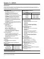
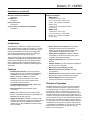
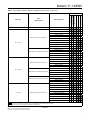
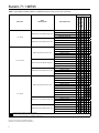
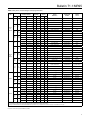
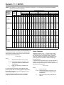
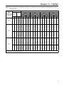
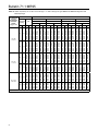
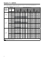
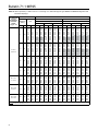
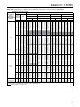
Bulletin 71.1:MR95
Table 10. Air Capacities(1)(2) in SCFH / Nm3/h for 1/4 NPT and 1/2 through 1 in. / DN 15 through 25 Types MR95L and MR95LD
Regulators with Elastomer Diaphragm
RECOMMENDED
OUTLET/
DIFFERENTIAL
PRESSURE
RANGE,
psig/psi / bar
2 to 6 /
0.14 to 0.41
PRESSURE
Outlet/
Differential
Setting
psig
bar
5
0.34
10
0.69
15
1.0
20
1.4
30
2.1
5 to 15 /
0.34 to 1.0
13 to 30 /
0.90 to 2.1
REGULATOR BODY SIZE, IN. / DN
Inlet
1/4 NPT
1/2 /15
3/4 / 20
1 / 25
Droop
Droop
Droop
Droop
10%
20%
10%
20%
10%
psig
bar
SCFH Nm3/h SCFH Nm3/h SCFH Nm3/h SCFH Nm3/h SCFH
20
30
50
75
100
150
200
250
20
30
50
75
100
150
200
250
20
30
50
75
100
150
200
250
30
40
50
75
100
150
200
250
40
50
75
100
150
200
250
1.4
2.1
3.4
5.2
6.9
10.3
13.8
17.2
1.4
2.1
3.4
5.2
6.9
10.3
13.8
17.2
1.4
2.1
3.4
5.2
6.9
10.3
13.8
17.2
2.1
2.8
3.4
5.2
6.9
10.3
13.8
17.2
2.8
3.4
5.2
6.9
10.3
13.8
17.2
740
950
1400
1600
1800
1800
1800
1800
670
950
1500
1800
2100
2200
2400
2400
600
930
1600
2000
2500
2600
2800
2800
710
970
1200
1700
2100
2500
2900
3000
880
1300
1900
2500
3100
3700
3900
19.8
25.4
36.5
43.3
48.3
48.3
48.3
48.3
18.1
25.5
40.4
48.5
56.6
60.3
64
64
16.1
25
42.8
54.9
67
70.6
74.2
76
19
25.9
32.9
44.6
56.3
66.5
76.7
80.5
23.6
35.3
51.8
68.2
83.2
98.1
104
910
1100
1500
1700
1900
2000
2000
2000
930
1200
1700
2000
2300
2300
2400
2400
830
1200
1900
2300
2700
2800
2800
2800
1100
1400
1700
2200
2700
2900
3100
3100
1400
1800
2500
3200
3600
4000
4000
24.5
30.2
41.5
46.9
52.2
53.6
53.6
53.6
24.9
31.6
44.9
53.3
61.7
62.9
64
64
22.3
32
51.4
62
72.7
74.1
75.6
76
29.1
37.5
45.9
59
72
77.5
83.1
82.6
38.6
48.7
67.2
85.6
96.2
107
108
1000
1100
1200
1300
1300
1500
1600
1500
1200
1300
1700
1700
1800
2000
2100
2300
1500
1800
2300
2400
2500
2700
2900
2900
1800
2100
2400
2600
2800
3000
3200
3500
2700
2900
3300
3800
4100
4400
4700
27.2
28.9
32.4
34.1
35.9
39
42.1
41
31.8
36
44.3
46.7
49.1
52.4
55.7
61.2
41.3
47.9
61.1
63.8
66.5
71.6
76.6
78.3
49
56.1
63.2
68.6
74
80.1
86.3
93.1
71
77.7
89.5
101
109
117
125
1500
1600
1700
1800
1800
2000
2100
2100
1900
2000
2400
2500
2700
2900
3000
3200
2200
2500
3000
3300
3500
3800
4100
4100
2900
3200
3600
3800
4000
4400
4700
4800
4200
4500
5000
5500
5900
6300
6600
41.2
42.7
45.5
47.5
49.5
52.6
55.6
56.4
50.6
54.9
63.5
67.7
71.8
76.5
81.1
84.9
59.5
66.7
81.2
87.1
93.1
101
109
110
77.2
86.9
96.6
103
108
117
125
129
113
121
134
147
159
170
176
1200
1400
1800
2300
2700
2400
2100
2000
1700
1900
2500
2800
3200
3500
3700
4300
1600
1900
2600
3000
3500
3900
4300
4700
2000
2200
2300
2900
3500
4000
4500
5000
2400
2700
3400
4000
4900
5900
6600
20%
10%
20%
Nm3/h
SCFH
Nm3/h
SCFH
Nm3/h
SCFH
Nm3/h
32.8
37.8
47.7
60.5
73.3
65
56.7
52.8
45.2
52.1
66.1
76
85.9
92.6
99.2
116
42.8
51.4
68.7
80.7
92.8
104
115
126
54.3
57.7
61.2
77
92.8
107
122
134
63
73.2
90.2
107
132
157
178
2200
2500
3200
3500
3900
4000
4000
3800
2700
3100
3800
4300
4700
5200
5700
6100
2500
3000
4200
4800
5300
5900
6600
7200
3400
3600
3900
4900
5800
6300
6800
7900
3500
4100
5200
6400
7700
8900
10,000
59.5
67.9
84.7
94.7
105
106
107
102
72.7
82.8
103
115
127
139
152
164
66.3
81.7
112
127
142
159
177
193
90.8
97.8
105
130
156
170
184
212
93.8
110
141
171
205
240
271
2800
3300
4200
4400
4600
4600
4600
4900
3000
3600
4900
5700
6500
6600
6700
6900
3200
4300
6500
7600
8700
8800
9000
9200
4400
5500
6500
8000
9500
11,000
12,000
12,000
6500
7900
10,000
12,000
14,000
16,000
16,000
74.7
87.5
113
118
123
123
122
131
80.1
97.1
131
153
175
178
180
184
85
115
174
204
233
237
240
247
117
146
176
215
254
282
309
315
174
212
272
333
376
420
429
4600
5200
6300
6700
7100
7400
7600
7900
4700
5800
8000
8700
9400
9800
10,000
11,000
4700
6600
10,000
12,000
13,000
13,000
14,000
14,000
7000
8800
11,000
13,000
15,000
16,000
17,000
17,000
9000
11,000
15,000
20,000
21,000
23,000
23,000
124
139
169
180
191
197
203
212
127
156
215
234
252
264
275
292
126
176
276
310
344
359
373
380
188
237
286
338
391
418
446
458
241
302
415
527
565
604
623
1. To obtain capacities for regulators using metal diaphragms, multiply the table values by 0.8.
2. To obtain capacities for regulators with reduced flow orifices, multiply the table values by 0.7.
To determine wide-open flow capacity for relief valve sizing of air
at a temperature of 60°F, use the equation for critical pressure
drops (absolute outlet pressure equal to one-half or less than
one-half the absolute inlet pressure).
Q = P1(abs)Cg
where,
Q
= Gas flow, SCFH (60°F and 14.7 psia)
P1(abs) = Absolute inlet pressure, psia (add 14.7 psi
to gauge inlet pressure to obtain absolute
inlet pressure)
Cg = Wide-open gas sizing coefficient from
Table 5
For pressure drops lower than critical (absolute outlet
pressure greater than one-half the absolute inlet pressure),
use the sizing nomographs in Fisher® Catalog 10, or the
Fisher Sizing Program.
To obtain capacities in Nm3/h at 0°C and 1.01325 bar,
multiply the capacity determined in SCFH by 0.0268.
14
Steam Capacities
Capacities in Tables 15, 16, 17, 18 and 19 are in lbs/h
of saturated steam. To obtain capacities in kg/h, multiply
the capacities given in the table by 0.4535. Capacities
have been calculated for stainless steel diaphragms only
since steam service exceeds the elastomer diaphragm
temperature limits.
To determine wide-open flow capacity for relief valve sizing
of steam, use the equation for critical pressure drops
(absolute outlet pressure equal to one-half or less than onehalf absolute inlet pressure).
Q = P1(abs)Cs
where,
Q
= Steam flow, lbs/h
P1(abs) = Absolute inlet pressure, psia (add 14.7 psi
to gauge inlet pressure to obtain absolute
inlet pressure)
Cs = Wide-open steam sizing coefficient from
Table 5