1
Bulletin 71.1:MR95
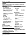
Installation
The MR95 Series regulators may be installed in any
position, as long as flow will be in the same direction as that
indicated by the body arrow. The Types MR95H, MR95L,
MR95HT and MR95HP regulators should be installed so
that their spring case vents are protected from anything that
might clog them.
Emerson Process Management Regulator Technologies, Inc.
(Emerson™) provides an instruction manual with every regulator
shipped. Refer to this for complete installation, operation and
maintenance instructions. Included is a complete list of individual
parts and recommended spare parts.
Universal NACE Compliance
Optional materials are available for applications handling sour
gases. These constructions comply with the recommendations
of NACE International sour service standards.
The manufacturing processes and materials used by
Emerson assure that all products specified for sour gas
service comply with the chemical, physical and metallurgical
requirements of NACE MR0175 ISO-2002 and/or
NACE MR0103. Optional materials are available to meet
ANSI/NACE MR0175/ISO 15156, please contact your local
Sales Office for special ordering instructions. Customers have
the responsibility to specify correct materials. Environmental
limitations may apply and shall be determined by the user.
Capacity Data
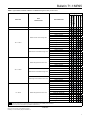
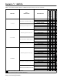
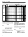
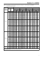
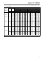
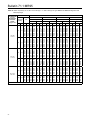
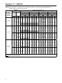
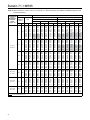
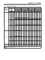
The capacity information on the following pages is based on
three droop factors, 10%, 20% and 40%. Droop is deviation
from the setpoint of the regulator, and is usually stated in
percentage of setpoint value.
For highest capacity and the most accurate control within a
particular type of the MR95 Series regulators, use the lowest
range spring that can be adjusted to the desired setpoint
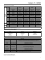
(see Table 3 for part numbers of appropriate springs for
each body size).
If closer control is necessary, a regulator of larger capacity
or different design should be selected, so that the necessary
flow can be obtained with a smaller droop factor.
Sometimes it may be necessary to interpolate the capacity
table data to determine capacity for outlet settings not given.
To maintain accuracy, it is important when interpolating to
stay within a spring range if possible. The following is a
procedure for interpolating the data to calculate flow:
1. Determine which spring is to be used.
2. Find the two outlet settings (P2a and P2b) that bracket
the actual outlet pressure P2.
4. Use the following formula to determine the interpolated
capacity (Q):
Qb - Qa
P2b - P2a
Qb - Q
=
P2b - P2
Example:
P1 = 100 psig / 6.9 bar
1/4 NPT Type MR95H with 15 to 30 psig / 1.0 to 2.1 bar
spring range
P2 = 20 psig / 1.4 bar
Determine air capacity, Q
Solution:
Qa = 1100 SCFH / 28.8 Nm3/h
P2a = 15 psig / 1.0 bar
Qb = 1700 SCFH / 46.5 Nm3/h
P2b = 30 psig / 2.1 bar
1700 - 1100
30 - 15
=
1700 - Q
30 - 20
Q = 1300 SCFH
46.5 - 28.8
2.1 - 1.0
=
46.5 - Q
2.1 - 1.4
Q = 35 Nm3/h
Note
The same interpolation procedure can be
used for different inlet pressures.
Contact your local Sales Office if you should have any
questions about selecting the proper regulator.
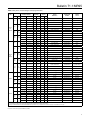
Air Capacities
Regulating capacities at selected pressures and outlet
pressure flows are given in SCFH (60°F and 14.7 psia)
of air. To determine the equivalent capacities for other gases,
multiply the table capacities by the following appropriate
conversion factors: 1.29 for 0.6 specific gravity natural gas,
0.808 for propane, 0.707 for butane or 1.018 for nitrogen.
For gases of other specific gravities, divide by the square root
of the appropriate specific gravity.
Then, if capacity is desired in Nm3/h at 0°C and 1.01325 bar,
multiply SCFH by 0.0268.
Capacities in Tables 10, 11, 12, 13 and 14 are for regulators
using elastomer diaphragms. Depending on regulator
construction, a multiplier must be used to convert to capacities
for regulators using metal diaphragms.
3. For a given body size and inlet pressure, find the
capacity Qa for P2a and Qb for P2b.
13