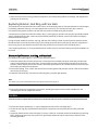
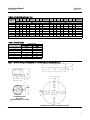
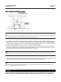
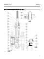
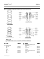
1
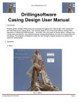
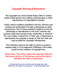
Instruction Manual V500 Valve D100423X012 November 2011 Fisherr V500 Rotary Control Valve Contents Introduction . . . . . . . . . . . . . . . . . . . . . . . . . . . . . . . . . 1 Scope of Manual . . . . . . . . . . . . . . . . . . . . . . . . . . . . . 1 Description . . . . . . . . . . . . . . . . . . . . . . . . . . . . . . . . . 1 Specifications . . . . . . . . . . . . . . . . . . . . . . . . . . . . . . . 2 Installation . . . . . . . . . . . . . . . . . . . . . . . . . . . . . . . . . . 2 Maintenance . . . . . . . . . . . . . . . . . . . . . . . . . . . . . . . . . 7 Packing Maintenance . . . . . . . . . . . . . . . . . . . . . . . . . 8 Replacing Retainer, Seat Ring, and Face Seals . . . . 10 Replacing Valve Plug, Shaft, and Bearings . . . . . . . 15 Adjusting Actuator Travel . . . . . . . . . . . . . . . . . . . . 20 Changing Valve Flow Direction . . . . . . . . . . . . . . . . 21 Changing Actuator Mounting Style . . . . . . . . . . . . 21 Parts Ordering . . . . . . . . . . . . . . . . . . . . . . . . . . . . . . . 21 Parts Kits . . . . . . . . . . . . . . . . . . . . . . . . . . . . . . . . . . . 22 Parts List . . . . . . . . . . . . . . . . . . . . . . . . . . . . . . . . . . . 24 Figure 1. Fisher V500 Flanged Rotary Control Valve with 1061 Actuator and FIELDVUE™ DVC6200 Digital Valve Controller W8380-1 Introduction Scope of Manual This instruction manual provides installation, operation, maintenance, and parts ordering information for NPS 1 through 8 Fisher V500 eccentric plug rotary control valves. Refer to separate manuals for information concerning the actuator and accessories. Do not install, operate, or maintain a V500 valve without being fully trained and qualified in valve, actuator, and accessory installation, operation, and maintenance. To avoid personal injury or property damage, it is important to carefully read, understand, and follow all the contents of this manual, including all safety cautions and warnings. If you have any questions about these instructions, contact your Emerson Process Management sales office before proceeding. Unless otherwise noted, all NACE references are to NACE MR0175-2002. Description The V500 rotary control valve is a flanged (figure 1) or flangeless valve with a self-centering seat, eccentrically rotating plug, and splined valve shaft. Suitable for forward or reverse flow use, this valve mates with a variety of actuators to provide throttling or on-off service. Both flanged and flangeless valves mate with CL150, 300, or 600 raised face pipeline flanges or DIN PN10 through PN100 flanges. www.Fisher.com Instruction Manual V500 Valve November 2011 D100423X012 Table 1. Specifications Valve Sizes(1) NPS J 1, J 1-1/2, J 2, J 3, J 4, J 6, and J 8. DN 25, 40, 50, 80, 100, 150 and 200 sizes are also available. End Connection Style J Raised-face flanges, J ring-type joint flanges (ASME B16.5), J or flangeless valve body designed to fit between raised face flanges. J CL150, J CL300, or J CL600; (CL600 is not available in NPS 6 and 8 flangeless valve bodies). DIN PN10 through PN100 flanges also available; consult your Emerson Process Management sales office Maximum Inlet Pressure(2) Consistent with applicable ASME B16.34 or EN 12516-1 ratings Flow Direction J Reverse Flow (Standard Direction): Past valve plug and through seat ring tends to close the valve, recommended for erosive and general service J Forward Flow: Through seat ring and past valve plug; tends to open the valve, recommended for high pressure drop and high cycle service Actuator Mounting J Left-hand or J right-hand as viewed from the upstream side of the valve. See figure 2 Valve Plug Rotation Counterclockwise to close (when viewed from actuator side of valve) through 90 degrees of valve plug rotation Shutoff Classification Class IV per ANSI/FCI 70-2 and IEC 60534-4 (0.01% of valve capacity at full travel), for either flow direction. Leak rates for full and restricted port valves are based on full port capacities. Reduced port valves seat at the full port diameter. Valve/Actuator Action Flow Characteristic Modified linear Shaft Diameters(3) and Approximate Weights With diaphragm or piston rotary actuator, field-reversible between J push-down-to-close (extending actuator rod closes the valve) and J push-down-to-open (extending actuator rod opens the valve) See table 2 1. The Valve Size shown in this manual refers to Nominal Pipe Size (NPS). 2. The pressure or temperature limits in this manual and any applicable standard limitations should not be exceeded. 3. Shaft diameter and spline end must match available shaft diameter of actuator. Installation WARNING Always wear protective gloves, clothing, and eyewear when performing any maintenance operations to avoid personal injury. To avoid personal injury or property damage resulting from the sudden release of pressure, do not install the valve assembly where service conditions could exceed the limits given on the appropriate nameplates, or the mating pipe flange rating. Use pressure-relieving devices as required by government or accepted industry codes and good engineering practices. Check with your process or safety engineer for any other hazards that may be present from exposure to process media. If installing into an existing application, also refer to the WARNING at the beginning of the Maintenance section in this instruction manual. CAUTION When ordered, the valve configuration and construction materials were selected to meet particular pressure, temperature, pressure drop, and controlled fluid conditions. Responsibility for the safety of process media and compatibility of valve 2 Instruction Manual V500 Valve D100423X012 November 2011 materials with process media rests solely with the purchaser and end-user. Since some valve body/trim material combinations are limited in their pressure drop and temperature ranges, do not apply any other conditions to the valve without first contacting your Emerson Process Management sales office. Table 2. Shaft Diameter and Approximate Weights APPROXIMATE WEIGHT SHAFT DIAMETER VALVE SIZE, NPS Through Valve At Spline End Flanged CL150 CL300 mm Flangeless CL600 CL150 CL300 kg CL600 kg 1 12.7 12.7 5.4 5.9 5.9 3.6 3.6 3.6 1-1/2 15.9 15.9 8.6 9.5 10 5.4 5.4 5.4 2 15.9 15.9 9.5 11 13 8.2 8.2 8.2 25.4 25.4 25.4 19.1 19 24 26 16 16 16 31.8 31.8 36 42 50 34 34 34 38.1 38.1 38.1 31.8 54 69 93 50 50 --- 98 135 57 68 --- 3 4 6 8 38.1 38.1 79 Inches lbs lbs 1 1/2 1/2 12 13 13 8 8 8 1-1/2 5/8 5/8 19 21 23 12 12 12 2 5/8 5/8 21 25 28 18 18 18 1 1 1 3/4 42 52 57 35 35 35 1-1/4 1-1/4 79 93 111 75 75 75 1-1/2 1-1/2 1-1/2 1-1/4 120 152 204 110 110 --- 1-1/2 1-1/2 75 217 298 125 150 --- 3 4 6 8 Key numbers in this procedure are shown in figure 11 (NPS 1 and 1-1/2 valves) or figure 13 (NPS 2 through 8 valves) unless otherwise indicated. CAUTION To prevent product damage during storage, keep the valve body cavity dry and clear of foreign material. 1. If the valve is to be stored before installation, protect the flange mating surfaces and keep the valve body cavity dry and clear of foreign material. 2. Install a three-valve bypass around the control valve assembly if continuous operation will be necessary during inspection and maintenance of the valve. 3. A V500 valve is normally shipped as part of a control valve assembly, with a power or manual actuator mounted on the valve. If the valve and actuator have been purchased separately or if the actuator has been removed from the valve, mount the actuator according to the Actuator Mounting procedure. Also, adjust the actuator travel using the Adjusting Actuator Travel procedure before installing the valve. The necessary measurements cannot be made with the valve installed. 4. Before starting the actual installation of the valve, determine the proper installation orientation of the valve plug (key 2) and actuator. Determine the flow direction of the process fluid through the valve. See figure 2. 3 V500 Valve November 2011 Figure 2. Index Marks for Actuator Lever Orientation 43A5323-D C0586-1 4 Instruction Manual D100423X012 Instruction Manual V500 Valve D100423X012 November 2011 Table 3. Line Stud (Key 36) M(1) Valve Size NPS Bolt Length Pressure Rating Qty Bolt Size CL150 4 5/8-11 UNC 10.62 CL300 6 3/4-10 UNC 11.12 CL600 6 3/4-10 UNC 11.50 CL150 6 5/8-11 UNC 11.44 CL300 6 3/4-10 UNC 12.12 CL600 6 7/8- 9 UNC 13.62 CL150 5 3/4-10 UNC 13.62 CL300 6 3/4-10 UNC 14.38 CL150 8 3/4-10 UNC 13.62 CL300 10 7/8- 9 UNC 15.38 3 4 6 8 Inches 1. These bolts may be installed from either end of the valve. Table 4. Line Stud (Key 36)(1) R Valve Size NPS Bolt Length Pressure Rating Qty Bolt Size CL150 6 3/4-10 UNC 5.00 CL300 6 3/4-10 UNC 5.00 CL150 --- --- --- CL300 4 7/8- 9 UNC 5.62 6 8 Inches 1. Use instead of cap screws. Table 5. Cap Screw (Key 37) N Valve Size NPS 3 4 P Bolt Length Overall Length Inches Inches Pressure Rating Qty Bolt Size CL150 --- --- --- --- CL300 4 3/4-10 UNC 2.38 2.88 CL600 4 3/4-10 UNC 2.38 2.88 CL150 4 5/8-11 UNC 2.00 2.44 CL300 4 3/4-10 UNC 2.38 2.88 CL600 4 7/8- 9 UNC 2.75 3.38 Figure 3. Line Bolt Dimensions for Flangeless Valve Bodies (also see tables 3, 4 and 5) M LINE STUDS LINE STUDS 1 CAP SCREWS R N P NOTE: USED INSTEAD OF CAP SCREWS 1 A4347 5 Instruction Manual V500 Valve November 2011 D100423X012 Figure 4. Optional Shaft-to-Body Bonding Strap Assembly VALVE BODY 37A6528-A A3143-2 VIEW A-A ACTUATOR A A Note For best shutoff performance and to reduce bearing wear, it is recommended that you install the valve shaft in a horizontal direction. See figure 1. 5. Before installing the valve, make sure the flow direction arrow (key 32) on the valve matches the actual process fluid flow direction through the valve for the application where the valve will be installed. 6. Install the flange gaskets and insert the valve between the mating pipeline flanges. For flangeless valve bodies, also make sure the mating line flanges are aligned. Use flat sheet gaskets compatible with the process media, or spiral wound gaskets with compression-controlling center rings. Ceramic Trim Some types of ceramic trim, including the VTC (very tough ceramic) variety, can create a spark under certain circumstances. When the edge of a ceramic part is struck against a second ceramic part with enough force, a spark can be created. WARNING Avoid personal injury and property damage from ignition of process fluid caused by sparks from ceramic trim. Do not use ceramic trim where the process fluid is unstable or if it is an explosive mixture (such as air and ether). WARNING The valve drive shaft is not necessarily grounded to the pipeline when installed. Personal injury or property damage could result if the process fluid or the atmosphere around the valve is flammable, from an explosion caused by a discharge of static electricity from the valve components. If the valve is installed in a hazardous area, electrically bond the drive shaft to the valve. 6 Instruction Manual D100423X012 V500 Valve November 2011 1. Prepare to install the line bolts and nuts. For flangeless valves, consult figure 3 before installing the line bolts and nuts. Figure 3 shows the line bolt clearances required when installing flangeless valves. Note Standard PTFE packing is composed of a partially conductive carbon-filled PTFE female adaptor with PTFE V-ring packing. Standard graphite packing is composed of all conductive graphite ribbon packing rings. Alternate shaft-to-valve body bonding is available for hazardous service areas where the standard packing is not sufficient to bond the shaft to the valve (see the following step). 2. For hazardous applications, attach the bonding strap assembly (key 131) to the shaft with the clamp (key 130) and connect the other end of bonding strap assembly to the valve body with the cap screw (key 25). See figure 4. For all valve bodies, install the line bolts and nuts; then, tighten them using accepted bolting procedures. These procedures include, but are not limited to, lubricating the line bolts and hex nuts and tightening the nuts in a crisscross sequence to ensure proper gasket load. 3. If a purge is desired for the purged bearing construction, remove the pipe plugs (keys 29 and 24) and install the purge lines. Purge pressure should be greater than the pressure within the valve and the purge fluid should be as clean as possible. 4. Connect pressure lines to the actuator as indicated in the actuator instruction manual. When a manual actuator is used with a power actuator, install a bypass valve on the power actuator (if not already supplied) for use during manual operation. WARNING Personal injury could result from packing leakage. Valve packing was tightened before shipment; however, the packing might require some readjustment to meet specific service conditions. Check with your process or safety engineer for any other hazards that may be present from exposure to process media. If the valve has ENVIRO-SEALt live-loaded packing installed readjustment will probably not be required. See the Emerson Process Management instruction manual entitled ENVIRO-SEAL Packing System for Rotary Valves, D101643X012 for packing instructions. If you wish to convert your present packing arrangement to ENVIRO-SEAL packing, refer to the retrofit kits listed in the Parts Kit section later in this manual. Maintenance WARNING Avoid personal injury or property damage from sudden release of process pressure or bursting of parts. Before performing any maintenance operations: D Do not remove the actuator from the valve while the valve is still pressurized. D Always wear protective gloves, clothing and eyewear when performing any maintenance operations to avoid personal injury. D Disconnect any operating lines providing air pressure, electric power, or a control signal to the actuator. Be sure the actuator cannot suddenly open or close the valve. D Use bypass valves or completely shut off the process to isolate the valve from process pressure. Relieve process pressure from both sides of the valve. Drain the process media from both sides of the valve. 7 V500 Valve Instruction Manual November 2011 D100423X012 D Vent the power actuator loading pressure and relieve any actuator spring precompression. D Use lock-out procedures to be sure that the above measures stay in effect while you work on the equipment. D The valve packing area may contain process fluids that are pressurized, even when the valve has been removed from the pipeline. Process fluids may spray out under pressure when removing the packing hardware or packing rings. D Check with your process or safety engineer for any other hazards that may be present from exposure to process media. Valve parts are subject to normal wear and must be inspected and replaced as necessary. The frequency of inspection and replacement depends upon the severity of service conditions. As used in these instructions, the term “actuator” refers to power actuators (such as pneumatic diaphragm or piston actuators) or manual actuators (such as handwheel or handlever actuators). Packing Maintenance Key numbers are referenced in figures 11 and 13 unless otherwise indicated. Note For the ENVIRO-SEAL packing system, refer to the Parts Ordering section for retrofit kits and parts kits(see figure 14). Refer to the separate ENVIRO-SEAL instruction manual for maintenance instructions. Standard ENVIRO-SEAL packing systems can be used in vacuum service with packing rings in the standard orientation. It is not necessary to reverse the ENVIRO-SEAL PTFE packing rings. Stopping Leakage All maintenance procedures in this section may be performed with the valve body (key 1) in the line. For packing other than spring-loaded packings, leakage around the packing follower (key 14) can be stopped by tightening the packing flange nuts (key 16). If leakage cannot be stopped in this manner, replace the packing according to the Replacing Packing procedure. If the packing is relatively new and tight on the valve shaft (key 3), and if tightening the packing nuts does not stop leakage, it is possible that the valve shaft is worn or nicked so that a seal cannot be made. If the leakage comes from the outside diameter of the packing, it is possible that the leakage is caused by nicks or scratches on the packing box wall. Inspect the shaft and packing box wall for nicks or scratches when performing the following procedures. Replacing Packing Note If the valve has ENVIRO-SEAL live-loaded packing installed, see the separate ENVIRO-SEAL instruction manual. This procedure may be performed without removing the actuator from the valve body if adding PTFE/composition packing rings as a temporary measure. However, the actuator must be removed if replacing any other kind of packing or if the metal packing parts (keys 14, 17, and, if used, 18) need to be replaced. 8 Instruction Manual D100423X012 V500 Valve November 2011 Removing the Packing 1. Isolate the control valve from the line pressure, release pressure from both sides of the valve, and drain the process media from both sides of the valve. If using a power actuator, also shut off all pressure lines to the power actuator, release all pressure from the actuator. Use lock-out procedures to be sure that the above measures stay in effect while you work on the equipment. CAUTION When the actuator is removed from the valve, do not use a hammer or similar tool to drive the lever or actuator off the valve shaft. Driving the lever or actuator off the valve shaft could damage the valve plug, seal, and valve. If necessary, use a wheel puller to remove the lever or actuator from the valve shaft. It is okay to tap the wheel puller screw lightly to loosen the lever or actuator, but hitting the screw with excessive force could damage the valve plug, seal, and valve. 2. If necessary, remove the cap screws (key 25) and hex nuts (key 26). Then remove the actuator while referring to the actuator manual for assistance. 3. Remove the packing nuts (key 16) and packing follower (key 14). 4. Remove the old packing rings (key 13), packing box ring (key 17), and, if used, the lantern ring (key 18). CAUTION Do not scratch the valve shaft or packing box wall. Scratching these surfaces could cause leakage. 5. Clean all accessible metal parts and surfaces to remove particles that would prevent the packing from sealing. 6. If necessary, complete the steps in the Replacing the Valve Plug, Shaft, and Bearings section, and return to the Installing Packing steps below. Installing Packing 1. Install the new packing rings and packing box ring by stacking the parts as shown in figure 5. Make sure split rings are arranged so that the splits do not line up to form a leak path. Then slide the stack into the packing box as far as will go while being careful to avoid trapping air among the rings. 2. Install the studs, packing follower, and nuts. CAUTION To prevent possible product damage or leakage, make sure the valve plug remains in the closed position when installing new packing parts. 3. Make sure the valve plug is in the closed position when installing new packing parts. 4. Insert a screw driver, pry bar, or similar tool between the lower ear of the plug and the valve body (see figure 6). Use the pry to move the plug tightly against the thrust washer and bearing on the actuator side of the valve. Keep the valve plug in that position until you have completed the packing installation. 5. Tighten packing flange nuts enough to stop leakage under normal conditions. 6. Mount the actuator while referring to the actuator mounting procedures of the actuator instruction manual. You must complete the Adjusting Actuator Travel procedure in this manual before installing the valve in the pipeline, due to the measurements that must be made during the actuator adjustment process. 9 V500 Valve Instruction Manual November 2011 D100423X012 7. When the control valve is being put back into operation, check the packing follower for leakage, and retighten the packing nuts as necessary. Replacing Retainer, Seat Ring, and Face Seals This procedure is to be performed if the control valve is not shutting off properly, if the port diameter is to be changed by installing a different seat ring, or if seat ring inspection is necessary. The actuator and valve (key 1) must be removed from the pipeline; however, the actuator may remain mounted during this procedure. A retainer tool is required to remove the retainer (key 5), seat ring (key 4), and face seals (key 8). If specifically ordered, a tool is supplied with the valve; a tool can also be ordered individually. If desired, a tool can be machined using the dimensions shown in figure 7. During assembly, handle the retainer, seat ring, and face seals carefully. Critical areas that must be protected are the threads and inner surface of the retainer (key 5), the sealing surfaces of the face seals (key 8), the face seal grooves in the seat ring (key 4), the shutoff surface of the seat ring, and the face seal surface in the valve body (key 1). A new retainer gasket (key 11) is required whenever the retainer (key 5) is removed. Other parts in good condition can be reused. Disassembly of Retainer, Seat Ring, and Face Seals Key numbers are shown in figures 11 and 13 unless otherwise noted. 1. Isolate the control valve from the line pressure, release pressure from both sides of the valve body, and drain the process media from both sides of the valve. If using a power actuator, also shut off all pressure lines to the power actuator, release all pressure from the actuator. Use lock-out procedures to be sure that the above measures stay in effect while you work on the equipment. 2. Remove line bolting. Then, remove the control valve from the pipeline and place the valve on a flat surface with the retainer (key 5) facing up. 3. Rotate the valve shaft (key 3) to move the valve plug (key 2) into the open position. Note The retainer (key 5) was installed at the factory using the torque listed in figure 8. 4. Remove the retainer by engaging the retainer tool, attaching an impact wrench or other suitable tool, and unscrewing the retainer. Inspect the retainer. CAUTION Place the retainer on a protected, flat surface where the threads and inner surface will not be contaminated or damaged. 5. Remove the retainer gasket (key 11). Inspect the gasket surfaces on the valve body (key 1). 6. Lift out the seat ring (key 4) and both face seals (key 8). Inspect the parts and place them on a flat, protected surface. 7. Inspect the shutoff surface of the valve plug. If it is worn, nicked, or scratched, proceed to the Replacing Valve Plug, Shaft, and Bearings procedure. If the parts are in good shape and do not require maintenance, continue to the Assembly procedure. 10 Instruction Manual V500 Valve D100423X012 November 2011 Figure 5. Packing Arrangements PACKING RING (KEY 13) LANTERN RING (KEY 18) ZINC WASHERS (KEY 28) PACKING BOX RING (KEY 17) ZINC WASHERS (KEY 28) PACKING RINGS (KEY 13) LANTERN RINGS (KEY 18) ZINC WASHER (KEY 28) PACKING BOX RING (KEY 17) DOUBLE PACKING ARRANGEMENT LEAKOFF ARRANGEMENT PTFE-BOUND COMPOSITION OR GRAPHITE RIBBON DOUBLE PACKING ARRANGEMENTS FEMALE ADAPTOR PACKING RINGS MALE ADAPTOR LANTERN RING (KEY 18) LANTERN RING (KEY 18) PACKING BOX RING (KEY 17) PRESSURE SERVICE PACKING BOX RING (KEY 17) VACUUM SERVICE LANTERN RING (KEY 18) LANTERN RING (KEY 18) PACKING BOX RING (KEY 17) PACKING BOX RING (KEY 17) PRESSURE/VACUUM SERVICE PTFE/V-RING DOUBLE PACKING ARRANGEMENTS ZINC WASHER (KEY 28) FEMALE ADAPTOR PACKING RINGS MALE ADAPTOR PACKING RINGS (KEY 13) LANTERN RING (KEY 18) LANTERN RING (KEY 18) FOR PURGED BEARING CONSTRUCTION FOR PURGED BEARING CONSTRUCTION PACKING RING (KEY 13) PACKING BOX RING (KEY 17) GRAPHITE RIBBON OR PTFE-COMPOSITION PACKING C0587-5 PACKING BOX RING (KEY 17) PTFE V-RING SINGLE PACKING ARRANGEMENTS NOTES: INCLUDES ZINC WASHERS (KEY 28) FOR GRAPHITE RIBBON PACKING ONLY. INCLUDED IN PTFE V-RING PACKING SET (KEY 13). FOR ONLY PTFE/BOUND-COMPOSITION PACKING, TOP RING IS CONDUCTIVE GRAPHITE FILAMENT RING. 11 Instruction Manual V500 Valve November 2011 D100423X012 Figure 5. Packing Arrangements (continued) PACKING FLANGE STUD (KEY 100) PACKING FLANGE NUT (KEY 101) PACKING FLANGE (KEY 102) GRAPHITE PACKING SET (KEY 105) PACKING BOX RING (KEY 107) SPRING PACK ASSEMBLY (KEY 103) GRAPHITE PACKING IN A STANDARD DEPTH BOX PTFE PACKING SET (KEY 105) ANTI-EXTRUSION RING (KEY 106) PACKING BOX RING (KEY 107) C0774-1 SINGLE PTFE PACKING IN A STANDARD DEPTH BOX PTFE/COMPOSITION OR GRAPHITE ENVIRO-SEAL PACKING ARRANGEMENTS Figure 6. Pry Bar Use PRY IN THIS DIRECTION ACTUATOR SIDE OF VALVE NOTE: 1. VALVE PLUG SHOULD BE IN THE OPEN POSITION WHEN TIGHT ENING THE PACKING FLANGE NUTS (KEY 16). 49A3685-D A7073 12 THRUST WASHER VALVE PLUG Instruction Manual V500 Valve D100423X012 November 2011 Table 6. Data for Making Retainer Tool VALVE SIZE, NPS A B C D E (HEX) F G H (SQUARE) A B C D 1 26.9 28.4 9.7 6.4 28.4 1-1/2(1) 36.6 28.4 9.7 1-1/2(2) 36.6 19.1 2 55.6 3 79.2 4 F G H (SQUARE) 1.5 4.8 --- 1.06 1.12 .38 .25 6.4 38.1 3.0 4.8 --- 1.44 1.12 .38 .25 1.12 .06 .19 --- 1.50 .12 .19 --- 6.4 --- 22.4 4.8 12.7 1.44 .75 --- --- .25 --- .88 .19 .50 19.1 --- 6.4 --- 22.4 4.8 12.7 2.19 .75 33.3 --- 7.9 --- 41.4 7.9 19.0 3.12 1.31 --- .25 --- .88 .19 .50 --- .31 --- 1.62 .31 104.6 33.3 --- 7.9 --- 41.4 7.9 25.4 4.12 .75 1.31 --- .31 --- 1.62 .31 1.00 6 155.4 38.1 --- 11.2 --- 63.5 11.2 25.4 8 203.2 50.8 --- 11.2 --- 101.6 11.2 38.1 6.12 1.50 --- .44 --- 2.50 .44 1.00 8.00 2.00 --- .44 --- 4.00 .44 1.50 mm E (HEX) Inches 1. Dimensions for 1-1/2 inch tool made from hex barstock, an optional material. 2. Dimensions for 1-1/2 inch tool made from round barstock. Table 7. Retainer Torque RETAINER TORQUE VALVE SIZE, NPS NSm LbfSft 1 140 100 1-1/2 185 135 2 260 190 3 515 380 4 1170 860 6 2305 1700 8 3120 2300 Figure 7. Data for Making and Using Retainer Tool (Key 33) (also see tables 6 and 7) B D A B C D F G A E (HEX) G H (SQ) RETAINER TOOL FOR NPS 1 VALVE (OPTIONAL FOR NPS 1-1/2 VALVE) B1899-2 RETAINER TOOL FOR NPS 1-1/2 THROUGH 8 VALVES 13 Instruction Manual V500 Valve November 2011 D100423X012 Assembly of Retainer, Seat Ring, and Face Seals WARNING Seat ring installation requires that the valve plug (key 2) remain in the open position. To avoid personal injury or damage to tools, valve parts, or other items resulting from plug closing, prevent plug travel by using travel stops, manual actuators, constant supply pressure to a pneumatic actuator, or other steps as appropriate. When installing the seat ring, keep hands, tools, and other objects out of the valve. 1. Apply enough supply pressure to the actuator to open the valve plug, or take other steps to hold the valve plug open. 2. Clean the valve body, the retainer threads, the retainer gasket surface, and the seat ring sealing surface. 3. Using either face seals (key 8) in good condition or new face seals, place one seal in the seat ring cavity. Table 8. Assembly Clearance SEAT RING AND RETAINER CLEARANCE VALVE SIZE mm Inches NPS Min Max Min Max 2 0.05 0.17 0.002 0.007 3, 4, 6, and 8 0.08 0.30 0.003 0.012 Note The seat ring (key 4) may have one or two shutoff surfaces. The shutoff surfaces are the narrow, rounded edges of the seat ring bore. Inspect the seat ring and locate the shutoff surfaces before proceeding. 4. Insert the seat ring into the seat ring cavity with the correct shutoff surface facing the valve plug and shaft. The seat ring will cover the face seal installed in step 3. 5. Place the second face seal on the seat ring. 6. Apply anti-seize lubricant to the gasket surface in the valve body. Install the gasket (key 11), while making certain that for NPS 2 through 8 sizes the concave surface of the gasket is up (hump surface of gasket down). 7. Apply anti-seize lubricant to the threads and bottom of the retainer (key 5). Thread the retainer into the valve body. 8. Refer to figure 7. With the appropriate torque indicating tool, tighten the retainer to the torque listed in table 7. 9. A gap between the seat ring (key 4) and retainer (key 5) allows the seat ring to self-center. Applying the proper amount of torque during installation should position the retainer and seat ring properly. However, for NPS 2 through 8 valves, use a feeler gauge to measure between the parts as shown in figure 13, making certain the necessary clearance exists. Compare the measured gap to the clearance in table 8 and proceed as follows: D If the measured clearance is within table values, proceed to the next step. D If the measured gap is larger than the maximum, tighten the retainer–apply more torque than that listed in table 7, if necessary–until the clearance is within maximum and minimum values. D If the measured clearance is smaller than the minimum, remove the retainer, seat ring, and face seals, clean the parts, and reassemble so as to obtain the necessary clearance. 10. Perform the Adjusting Actuator Travel procedure and then install the control valve in the pipeline. 14 Instruction Manual D100423X012 V500 Valve November 2011 Replacing Valve Plug, Shaft, and Bearings Perform this procedure to replace the valve plug (key 2), expansion pin assembly (keys 9 and 10), shaft (key 3), or bearings (key 6). These parts are independently replaceable; for example, installing a new valve plug does not require replacing a reusable valve shaft or expansion pin assembly. Key numbers refer to figures 11 and 13 unless otherwise indicated. Disassembly of Valve Plug, Shaft, and Bearings WARNING To avoid personal injury resulting from contact with edges of the valve plug (key 2) and seat ring (key 4) during plug rotation, stay clear of the plug edges when rotating the plug. To avoid damage to tools, valve parts, or other items resulting from valve plug rotation, keep tools and other property away from the edges of the plug. CAUTION To avoid increased leakage, increased valve component wear or possible damage to the valve body (key 1), plug (key 2), shaft (key 3), and bearings (key 6) resulting from a sharp blow to the actuator body or valve parts, use a wheel puller to separate the actuator parts from the valve shaft. Do not drive the actuator parts off the valve shaft since this could move the valve bearings, shaft, and plug away from proper alignment, causing improper seating of the plug. Such misalignment may result in damage to valve components if the valve is returned to service without disassembly and inspection of the valve plug alignment. Note Following removal of the valve from the pipeline and partial disassembly, the valve shaft may be used to remove bearings in accordance with the procedure described in step 8, below. 1. Isolate the control valve from the line pressure, release pressure from both sides of the valve body, and drain the process media from both sides of the valve. If using a power actuator, also shut off all pressure lines to the power actuator, release all pressure from the actuator. Use lock-out procedures to be sure that the above measures stay in effect while you work on the equipment. 2. Remove the actuator cover. Note the actuator orientation with respect to the valve body and the lever orientation with respect to the valve drive shaft (see figure 2). Remove the lever but do not loosen the actuator turnbuckle adjustment. Remove the actuator mounting screws and nuts, and remove the actuator. If necessary, refer to the actuator instruction manual for assistance. 3. With the valve body (key 1) out of the pipeline, loosen the packing nuts (key 16). If the packing is to be reused, do not remove it. However, Emerson Process Management recommends that the packing be replaced whenever the drive shaft is removed. 4. Rotate the plug (key 2) to the fully open position. 15 Instruction Manual V500 Valve November 2011 D100423X012 Figure 8. Detail of Valve Plug for Pin Removal DRIVE PINS OUT FROM THIS END (SMALLER HOLE) SLASH MARK ON SPLINED END OF SHAFT A3307-1 Table 9. Data for Tapped Hole in Valve Shaft SHAFT DIAMETERS Through Valve Body mm mm 1 12.7 12.7 0.50 0.50 10-24 1-1/2 15.9 15.9 0.62 0.62 1/4-20 2 15.9 12.7 0.62 0.62 10-24 25.4 15.9 1.00 1.00 3/8-16 25.4 25.4 1.00 0.75 5/16-18 31.8 19.1 1.25 1.25 3/8-16 38.1 38.1 1.50 1.50 1/2-13 38.1 31.8 1.50 1.25 3/8-16 38.1 38.1 1.50 1.50 1/2-13 3 4 6 8 At Spline End Through Valve Body At Spline End THREAD SIZE, UNC VALVE SIZE, NPS Inches 5. Refer to figure 8. Find the expansion pin (key 9) and the taper pin (key 10) inside of it. These parts are holding the valve plug in position on the shaft. Find the larger hole in the valve plug hub where these pins enter the hub. On the opposite side of the plug hub is a smaller hole where the chamfered end of the expansion pin rests on the inner lip of the hole. Using a pin punch and hammer, strike the chamfered end of the expansion pin through the smaller hole. Remove both pins from the valve plug hub in the direction shown in figure 8. Driving the pins in the other direction will tighten the pins. WARNING To avoid personal injury or damage to tools, valve parts, or other items and plug damage resulting from the valve plug falling from the valve body, support the plug to prevent it from falling as the shaft (key 3) is being removed. 6. Pull the shaft (key 3) from the valve body. If the shaft cannot be removed by hand, attach a slide hammer or similar tool to the spline end of the valve shaft. Each shaft, on the NPS 6 and 8 sizes, has a tapped hole at the spline end of the shaft; refer to table 9 for thread sizes. 16 Instruction Manual V500 Valve D100423X012 November 2011 7. Remove the plug and thrust washer (key 12) from the valve body. Note Two shaft bearings (key 6) are located inside the valve body on either side of the valve plug. Only one of these two bearings is identified by key 6. The other bearing is located along the valve shaft on the other side of the valve plug. 8. If the shaft bearings are to be replaced, remove the packing (key 13). 9. If the bearing closest to the packing requires replacement and cannot be removed by hand, press it out using a ram with dimensions given in figure 9 and table 10. CAUTION Ensure the bearing stop is not moved when pressing out the bearing. Movement may cause the new bearing and valve plug to not be centered with the seal, causing possible leakage or damage of the seal/plug. Insert the ram through the packing box and press the bearing into the valve body cavity. The bearing stop (key 7) does not need to be removed; take care not to move the bearing stop when pressing out the bearing. 10. If the second bearing (key 6) requires replacement and cannot be removed by hand, use one of the following methods: D Knock or pry the bearing out, or D Use the valve shaft as a piston to drive the bearing from the valve body. To accomplish this, first, fill the bearing bore with a heavy grease and then insert the end of the shaft back through the valve body and into the grease-filled bearing. Protect the splined end of the shaft with, for example, a block of wood; then strike the protected end. When the shaft is struck, it will act as a piston, pushing the grease into the bearing bore. The grease will then force the bearing out of the bore and farther along the shaft. Soon, the bearing will be positioned for easy removal. 11. If used, remove the O-rings (keys 19 and 20) from the bearings. Also, remove the pipe plug (key 29). Table 10. Ram Dimensions A MAXIMUM MINIMUM VALVE SIZE, NPS L mm Inches mm Inches 1 15.1 14.7 .594 .578 114 4.50 1-1/2 18.3 17.9 .719 .703 114 4.50 2 18.3 17.9 .719 .703 127 5.00 3 27.8 27.4 1.094 1.078 127 6.50 4 34.1 33.7 1.344 1.328 165 6.50 6 42.1 41.7 1.656 1.641 197 7.75 8 42.1 41.7 1.656 1.641 129 9.00 17 Instruction Manual V500 Valve November 2011 D100423X012 Figure 9. Ram Dimension for Bearing Removal (also see table 10) L A A3308 Assembly of Valve Plug, Shaft, and Bearings Note Before starting to assemble the valve components, place the valve body (key 1) on a flat surface with the retainer (key 5) facing down as shown in figure 10. This orientation of the valve body allows easier installation of the valve plug. 1. Thoroughly clean the parts before assembly. 2. If O-rings (keys 19 and 20) are used, apply a small amount of lubricant to the O-rings so the bearings will easily slide into the valve body. Insert the smaller O-ring (key 20) inside the bearing and the larger O-ring (key 19) around the outside of the bearing. CAUTION To avoid damage to O-rings resulting from contact with sharp edges within the bearing holes, use appropriate care when installing the O-rings. 3. Slide the bearings (key 6) and O-rings (keys 19 and 20), if used, into the valve body as shown in figures 13 and 12. Note Place the valve body on a flat surface with the retainer (key 5) facing down so that you can look into the valve body cavity. This orientation makes installing the valve plug easier. 4. Inspect the valve shaft (key 3). Insert the shaft end opposite the splined end into the packing box and through the set of bearings installed in the packing box in step 3. Stop before the shaft enters the main valve body cavity. Support the splined end of the shaft. 5. Determine the correct orientation of the valve plug (key 2) required by the specific installation orientation of the valve and the flow direction of the process fluid. See figure 2. 6. Inspect the valve plug. Note the location of the larger hole on the valve plug hub. Place the valve plug in the valve body cavity. 7. Position the valve plug so that the larger hole is facing up, away from the seat ring and retainer. The valve plug must also be oriented so that the seating surface of the plug is correctly positioned for the specific application as shown by the illustrations in figure 2. 18 Instruction Manual V500 Valve D100423X012 November 2011 Figure 10. Detail of Valve Plug for Pin Insertion PINS GO IN FROM THIS END (LARGER HOLE) SLASH MARK ON SPLINED END OF SHAFT BENCH A3309-1 Note Before proceeding, inspect the valve plug position once again to ensure the correct orientation as described in step 6. If the valve plug is not properly installed, it will not rotate properly and will not shutoff in service. 8. Hold the thrust washer(s) (key 12) between the valve plug (key 2) and the bearing installed next to the packing as shown in figures 11 and 13. Then slide the valve shaft (key 3) from the packing box into the valve body through the thrust washer(s) and plug. If the shaft material is S17400, use two 0.7938 mm (1/32 inch) 17-7 PH thrust washers. If the shaft material is S20910, use one 1.587 mm (1/16 inch) alloy 6 thrust washer. 9. Secure the valve plug in the correct open position. Inspect the splined end of the valve shaft and locate the slash mark on the splined end. Rotate the valve shaft until the slash mark is vertical and facing out from the center of the shaft in the same direction as the valve plug seating surface. See figure 10. Note When the valve shaft is correctly positioned, the slash mark on the splined end will be parallel with the plug shutoff surface. See figure 10. 10. Look into the valve body and find the larger pin hole on one side of the valve plug hub. Find the smaller hole on the opposite side of the hub. These holes should line up with the hole through the shaft (key 3). Note If the holes in the valve plug hub do not line up with the hole in the shaft, check the slash mark on the splined end of the shaft. Make sure the shaft and plug are properly oriented. CAUTION For NPS 1 through 2, use only N10276 expansion and taper pins (keys 9 and 10) with VTC (ceramic) valve plug. With any other pin material, there is danger of the pins expanding and cracking the plug as temperature rises. For that reason, the 19 V500 Valve Instruction Manual November 2011 D100423X012 NPS 1 through 2 VTC valve plugs are sold only as a set that includes N10276 pins. Use only the pins that are furnished with the set. Components of the VTC valve plug assembly for the NPS 3 through 8 cannot be repaired in the field. 11. Place the chamfered end of the expansion pin (key 9) into the larger hole in the plug hub (see figure 11). CAUTION To avoid damage to the expansion pin, valve plug, or shaft resulting from the application of excessive force on the expansion pin, use appropriate care when driving the expansion pin through the plug hub and shaft. Use the right tool. Do not use excessive force. 12. Drive the expansion pin into the larger hole until the chamfered end of the pin reaches the inner lip of the smaller hole on the opposite side of the plug. Closely observe the progress of the pin to avoid striking it after it has reached the lip of the smaller hole. 13. Place the taper pin (key 10) into the open end of the expansion pin. Drive the taper pin into the expansion pin until the pins, plug, and shaft are snug. Do not attempt to drive either pin flush with the hub. 14. Rotate the plug by hand to check that it rotates properly. If rotation interferes with the valve body, drive out the pins (keys 9 and 10), remove the valve shaft (key 3), and repeat this procedure starting with step 4. 15. If used, install the pipe plug (key 29). 16. If the seat ring (key 4), face seals (key 8), and retainer (key 5) need to be installed, complete the assembly instructions in the procedure for Replacing Retainer, Seat Ring, and Face Seals. If the seat ring has previously been installed, proceed to Adjusting Actuator Travel. Adjusting Actuator Travel Perform this procedure whenever the actuator is removed or disconnected from the valve and whenever the seat ring and retainer (keys 4 and 5) are removed. Actuator travel that is too short will increase shutoff leakage; too much travel will cause excessive plug and seat ring torque. Any of the Fisher pneumatic (spring-and- diaphragm, piston, or spring-return piston), electric, electrohydraulic, or manual actuators--or any other operator--must be adjusted for use with a V500 valve so that the valve plug is rotated to the fully closed position. The fully closed position is obtained when a gap of 0.001 inch exists between the seat ring (key 5) and retainer (key 4). Note that this gap is also measured when assembling the seat ring, retainer, and face seals to ensure correct assembly. Measure the gap according to this procedure to ensure proper actuator adjustment. Merely completing the assembly measurement is not sufficient. Travel for different actuators is adjusted differently (some use turnbuckle assemblies; some use externally adjusted travel stops; others use internal limit switches). Refer to the actuator instruction manual for adjustment instructions. 1. Mount the actuator following the instructions in the actuator instruction manual. Refer to figure 3 to select actuator mounting style and position and to orient the actuator lever with the valve shaft (key 3). 2. For actuators with clamped levers, CAUTION When installing the actuator onto the valve, do not use a hammer or similar tool to drive the lever or actuator onto the valve shaft. Driving the lever or actuator onto the valve shaft could damage the valve plug, seal ring, and other valve components. 20 Instruction Manual D100423X012 V500 Valve November 2011 D Clean the valve shaft splines and actuator lever splines to be sure the actuator lever will slide on easily. D Pull the valve shaft (key 3), by hand, toward the packing (key 13). Or, D If the lever does not slide easily on the valve shaft, carefully wedge the valve plug solidly against the actuator-side thrust washer using a screwdriver or similar tool in the same direction as the pry bar shown in figure 6. 3. Clamp the lever to the valve shaft. CAUTION Do not apply full actuator signal (pressure or power) to the actuator in the next step. Full signal may wedge the valve plug into the seat ring. Use a regulated signal source and gradually increase the signal to slowly stroke the actuator. 4. Adjust actuator travel and stroke the actuator so that the plug is close to but not contacting the seat ring at full actuator travel. If available on electric actuators, use a manual handwheel to position the plug. 5. Adjust travel, using full actuator signal, until the valve plug contacts the seat ring around its full circumference. This contact self-centers the seat ring on the valve plug. 6. Continue to adjust travel until a gap of 0.001 inch exists between the seat ring and retainer, as shown in figure 13, at full actuator travel. 7. Refer to the actuator instruction manual to lock the actuator travel adjustment. Changing Valve Flow Direction The V500 valve may be installed in either forward or reverse flow service. Forward flow enters the seat ring first, then flows past the valve plug. If changing flow direction is necessary, release all pressure from the valve and actuator. Remove the control valve assembly from the pipeline and rotate the assembly about the valve shaft to put the retainer end of the valve where the other end was. Refer to the procedure for Changing Actuator Mounting Style if the actuator must be repositioned, and refer to the Installation section to install the control valve assembly. Be sure to reposition the flow direction arrow on the valve body. Changing Actuator Mounting Style Refer to figure 3 of this manual and the actuator instruction manual when changing mounting styles or positions. Right-hand mounting places the actuator on the right side of the valve as viewed from the upstream side of the valve; left-hand mounting places the actuator on the left side of the valve. Remember that the upstream side of the valve inlet is the retainer end of the valve body for forward flow and the other end of the valve body is the upstream side for reverse flow. Complete the Adjusting Actuator Travel procedure whenever the actuator is removed. Parts Ordering A serial number is assigned to each valve and stamped on the nameplate. Always refer to the valve serial number when corresponding with your Emerson Process Management sales office. When ordering replacement parts, also specify the part name and desired material. WARNING Use only genuine Fisher replacement parts. Components that are not supplied by Emerson Process Management should not, under any circumstances, be used in any Fisher valve, because they may void your warranty, might adversely affect the performance of the valve, and could cause personal injury and property damage. 21 Instruction Manual V500 Valve November 2011 D100423X012 Parts Kits Repair Kits Repair kits include recommended spares for standard and sealed bearing constructions. Parts Included in Kits Valve Size NPS Kit Parts Number 1 RV500X00012 1 1-1/2 RV500X00022 Taper pin 1 2 RV500X00032 11 Retainer gasket 1 3 RV500X00042 19 O-ring (sealed bearing only) 2 4 RV500X00052 20 O-ring (sealed bearing only) 2 6 RV500X00062 8 RV500X00072 Key Number Description 9 Expansion pin 10 Quantity in Kit Repair Kits for ENVIRO-SEAL Packing Packing boxes in these valves may be deep-drilled. If the valve being repaired has a deep packing box, additional parts are required. Refer to the Packing Maintenance section in this manual. Parts included in Kits Quantity in Kit Valve Size NPS Kit Parts Number 1 RRTYX000012 1-1/2 & 2 RRTYX000022 1 3 RRTYX000052 - - -(1) 4 RRTYX000062 6&8 RRTYX000072 Key Number Description PTFE Graphite 105 Packing Set 1 106 Anti-Extrusion Washer 2 1. Included in packing set, key 105. Retrofit Kits for ENVIRO-SEAL Packing Retrofit kits include parts to convert existing V500 valves with single depth packing box to the ENVIRO-SEAL packing box construction. Retrofit kits include single PTFE or graphite packing box construction (see following table). Parts included in Kits Quantity in Kit Valve Size NPS Kit Parts Number 1 RRTYXRT0012 1-1/2 & 2 RRTYXRT0022 2 3 RRTYXRT0052 2 2 4 RRTYXRT0062 Packing flange 1 1 6&8 RRTYXRT0072 Spring pack assembly 1 1 105 Packing set 1 1 106 Anti-extrusion washer 2 --- 107 Packing box ring 1 1 Key Number Description PTFE Graphite 100 Packing stud 2 101 Packing nut 102 103 Table 11. Explanation of Valve Construction(1) For These Packing and Bearing Constructions Use These Valve Constructions Single packing and standard bearings Standard packing box without end tapping Single packing and sealed bearings Standard packing box with end tapping Double packing and standard bearings Deep packing box without lube or end tapping Leakoff packing and standard bearings Deep packing box with only lube tapping Double packing and sealed bearings Deep packing box with only lube tapping Leakoff packing and sealed bearings Deep packing box with both lube and end tapping Purged bearing and single packing for purged bearings Deep packing box with both lube and end tapping 1. Please contact your Emerson Process Management sales office for more information. 22 Instruction Manual V500 Valve D100423X012 November 2011 Figure 11. Fisher V500 Rotary Control Flange Valve, NPS 1 and 1-1/2 DOUBLE PACKING OPTIONAL PIPE PLUG OPTIONAL SEALED BEARING V APPLY LUBRICANT 39A9677-D 23 Instruction Manual V500 Valve November 2011 D100423X012 Figure 12. Valve Plug Views SHUTOFF SURFACE VALVE PLUG SEATING SURFACE HUB B2423-1 STANDARD VALVE PLUG DETAIL (TOP VIEW) ALL SIZES 24B9722-B / DOC CAP SCREW VTC (CERAMIC) VALVE PLUG FOR NPS 3 THROUGH 8 CERAMIC TRIM AVAILABLE PRE-ASSEMBLED ONLY Parts List Key Note Part numbers are shown for recommended spares only. For part numbers not shown, contact your Emerson Process Management sales office. 9* 10* Valve Common Parts (figures 11 and 13) Key 1 2 3 4* 5 6* 7 8* 24 Description Part Number Valve Body/Bearing Assembly If you need a valve body as a replacement part, order by valve size, serial number, and desired material. Valve Plug Valve Shaft Seat Ring Full Port, Metal seat construction See following table Retainer Bearing (2 req'd) See following table Bearing Stop, S31600 (316 SST) Face Seal, (2 req'd) Metal NPS 1 19A5160X022 NPS 1-1/2 19A5145X022 NPS 2 19A3747X022 NPS 3 19A3716X022 NPS 4 19A3680X042 NPS 6 19A4243X032 NPS 8 19A3649X022 PTFE NPS 1 10B9116X012 NPS 1-1/2 10B9117X012 NPS 2 10B8275X022 NPS 3 10B9118X012 NPS 4 10B9119X012 11* 12 13* VTC (CERAMIC) VALVE PLUG FOR NPS 1, 1-1/2, AND 2 (NPS 1 SHOWN) Description NPS 6 NPS 8 Expansion Pin, S20910 NPS 1 19A5163X012 NPS 1-1/2 & 2 NPS 3 19A3717X012 NPS 4 19A3681X012 NPS 6 & 8 Taper Pin, S20910 NPS 1 16A5511X012 NPS 1-1/2 & 2 NPS 3 F14114X0012 NPS 4 16A5515X012 NPS 6 & 8 Retainer Gasket NPS 1, graphite laminate NPS 1-1/2, graphite laminate NPS 2, S31600 NPS 3, S31600 NPS 4, S31600 NPS 6, S31600 NPS 8, S31600 Thrust Washer (1) Packing Set PTFE & carbon-filled V-ring set (conductive) Single & purged bearing construction - 1 req'd Double - 2 req'd NPS 1 NPS 1-1/2 & 2 NPS 3 NPS 4 NPS 6 & 8 PTFE V-ring set (nonconductive) Single & purged bearing construction - 1 req'd Double - 2 req'd NPS 1 NPS 1-1/2 & 2 NPS 3 NPS 4 NPS 6 & 8 *Recommended spare parts 1. A single quantity of the part number is needed - you will receive two thrust washers when you specify 17-7PH. Part Number 10B9120X012 10B9121X012 19A3750X012 19A3687X012 19A3749X012 H13748K0032 19A5162X022 19A5176X022 19A5197X012 19A5198X012 19A5199X012 19A5200X012 19A6401X012 12A9016X022 1R5795X0012 12A8832X022 12A8951X022 12A8935X022 12A9016X012 1R5795D1012 12A8832X012 12A8951X012 12A8935X012 Instruction Manual V500 Valve D100423X012 November 2011 Figure 13. Fisher V500 Rotary Control Valve, NPS 2, 3, 4, 6, and 8 DOUBLE PACKING PIPE PLUG OPTIONAL SEALED BEARING OPTIONAL MEASURE GAP HERE 49A3686-F APPLY LUB 25 Instruction Manual V500 Valve November 2011 Key 13* 14 15 16 17* 18 19* 20* 26 Description D100423X012 Part Number Key Packing Set (continued) PTFE/bound composition rings Single & purged bearing construction Conductive - 3 req'd & graphite filament ring Nonconductive - 4 req'd Double or Leakoff Conductive - 5 req'd & graphite filament ring Nonconductive - 6 req'd NPS 1 1P3905X0172 NPS 1-1/2 & 2 1J8225X0142 NPS 3 14A0915X012 NPS 4 14A0916X012 NPS 6 & 8 14A1933X012 Graphite filament ring - 1 req'd use with PTFE/bound composition conductive packing NPS 1 1P3905X0172 NPS 1-1/2 & 2 1J8225X0182 NPS 3 14A0915X042 NPS 4 14A0916X072 NPS 6 & 8 14A1933X022 Graphite ribbon rings Single & purged bearing construction - 4 req'd Double or Leakoff - 6 req'd NPS 1 12A9134X012 NPS 1-1/2 & 2 12A9135X012 NPS 3 12A9137X012 NPS 4 12A9138X012 NPS 6 & 8 12A9139X012 Packing Follower, CF8M (316 SST) Packing Flange Stud (2 req'd) Packing Flange Nut (2 req'd) Packing Box Ring, S31600 NPS 1 16A6082X012 NPS 1-1/2 & 2 16A6083X012 NPS 3 16A6085X012 NPS 4 16A6086X012 NPS 6 & 8 16A6087X012 Lantern Ring, S31600 O-Ring (for sealed bearings; 2 req'd) Nitrile NPS 1 11A8741X052 NPS 1-1/2 & 2 1F4636X0032 NPS 3 10A3804X012 NPS 4 1W1932X0032 NPS 6 & 8 13A2331X022 Fluorocarbon NPS 1 11A8741X012 NPS 1-1/2 & 2 1N571406382 NPS 3 10A3804X032 NPS 4 1W1932X0032 NPS 6 & 8 13A2331X012 O-Ring (for sealed bearings; 2 req'd) Nitrile NPS 1 1J4888X0052 NPS 1-1/2 & 2 11A8741X052 NPS 3 10A8217X042 NPS 4 10A3803X012 NPS 6 & 8 1F1153X0012 Fluorocarbon NPS 1 1J4888X0032 NPS 1-1/2 & 2 11A8741X012 NPS 3 10A8217X012 NPS 4 10A3803X032 NPS 6 & 8 1F1153X0022 21 22 23 24 24 Description 25 26 28* 29 30 31 32 33 36 37 130 131 Part Number Anti-seize lubricant (not furnished with valve) Nameplate, SST Drive Screw, SST (6 req'd) Pipe Plug, S31700 Isolator/Lubricator Valve (not shown) Pipe nipple (not shown) Cap Screw Hex Nut Packing Washer (not shown) Zinc (for graphite/ribbon pkg only) Single - 3 req'd Double or leakoff - 4 req'd NPS 1 14A8362X012 NPS 1-1/2 & 2 14A9771X012 NPS 3 14A8365X012 NPS 4 14A8366X012 NPS 6 & 8 14A8367X012 Pipe Plug (for sealed or purged bearing constructions) Optional Nameplate (not req'd when actuator is furnished) Nameplate Wire, steel (not req'd when actuator is furnished) Flow Arrow, SST Retainer Tool, steel (not shown) Line Studs (for flangeless valve bodies) - see following table for number required Cap Screws (for flangeless valve bodies) - see following table for number required Clamp SST (req'd w/ nonconductive packing) Bonding Strap Assembly (req'd w/nonconductive packing) ENVIRO-SEAL Packing System (figure 14) 100 Packing Flange Stud (2 req'd) SA193 B7 zn pl NPS 1, 1-1/2 & 2 NPS 3 NPS 4 NPS 6 & 8 SA193 B8M NPS 1, 1-1/2 & 2 NPS 3 NPS 4 NPS 6 & 8 SA193 B7M (NACE MR0175-2002) NPS 1, 1-1/2 & 2 NPS 3 NPS 4 NPS 6 & 8 101 Packing Flange Nut (2 req'd) SA193 2H zn pl NPS 1, 1-1/2 & 2 NPS 3 NPS 4, 6, & 8 SA193 8M NPS 1, 1-1/2 & 2 NPS 3 NPS 4, 6, & 8 SA193 2HM (NACE MR0175-2002) NPS 1, 1-1/2 & 2 102 Packing Flange, SST 103 Spring Pack Assembly 105* Packing Set PTFE NPS 1 *Recommended spare parts 11B3814X102 16A1061X082 12A8926X012 1P568231032 11B3814X102 16A1061X022 12A8926X022 1P568235222 11B3814X032 16A1061X042 12A8926X032 1P5682X0062 1E944024112 1A375324112 1A341224112 1E944035252 1A375335252 1A341235252 1E9440X0012 12B7053X012 Instruction Manual V500 Valve D100423X012 November 2011 Figure 14. ENVIRO-SEAL Rotary Packing Arrangements with PTFE and Graphite Packing SINGLE PTFE PACKING STANDARD DEPTH BOX STACKING ORDER OF PTFE PACKING RINGS STACKING ORDER OF GRAPHITE PACKING RINGS GRAPHITE PACKING STANDARD DEPTH BOX NOTES: APPLY LUBRICANT. THESE TWO SURFACES SHOULD REMAIN PARALLEL AS YOU ALTERNATELY AND EVENLY TIGHTEN THE PACKING NUTS (KEY 101). Key Description 105* Packing Set (continued) PTFE NPS 1-1/2 & 2 NPS 3 NPS 4 NPS 6 & 8 Graphite NPS 1 NPS 1-1/2 & 2 NPS 3 NPS 4 NPS 6 & 8 *Recommended spare parts Part Number 12B7402X012 12B7438X012 12B7450X012 12B7462X012 13B8816X012 13B8816X032 13B8816X092 13B8816X112 13B8816X142 Key Description 106* Anti-Extrusion Ring, Composition/graphite filled PEEK (2 req'd) Single PTFE packing w/std packing box NPS 1 NPS 1-1/2 & 2 NPS 3 NPS 4 NPS 6 & 8 Double PTFE packing w/std & deep pkg box NPS 1 NPS 1-1/2 & 2 NPS 3 NPS 4 Part Number 12B7504X012 12B7406X012 12B7442X012 12B7454X012 12B7466X012 12B7504X012 12B7406X012 12B7442X012 12B7454X012 27 Instruction Manual V500 Valve November 2011 Key D100423X012 Description Key Part Number 107* Packing Box Ring Single PTFE packing w/std packing box NPS 1 16A6082X012 NPS 1-1/2 & 2 16A6083X012 NPS 3 16A6085X012 NPS 4 16A6086X012 NPS 6 & 8 16A6087X012 Double PTFE packing w/std packing box NPS 1 16A6082X012 NPS 1-1/2 & 2 16A6083X012 NPS 3 16A6085X012 NPS 4 16A6086X012 Double PTFE packing w/deep packing box (2 req'd) NPS 1 12B7062X012 NPS 1-1/2 & 2 12B7412X012 NPS 3 12B7448X012 NPS 4 12B7460X012 Graphite packing w/std packing box NPS 1 16A6082X012 NPS 1-1/2 & 2 16A6083X012 NPS 3 16A6085X012 NPS 4 16A6086X012 NPS 6 & 8 16A6087X012 Description Part Number 108* Packing Ring Double PTFE packing w/std & deep pkg box (2 req'd) NPS 1 1H7844X0012 NPS 1-1/2 & 2 1R5794X0012 NPS 3 12A8831X022 NPS 4 12A8953X022 109* Anti-Extrusion Ring Double PTFE packing w/std & deep pkg box NPS 1 12B7473X012 NPS 1-1/2 & 2 12B7410X012 NPS 3 12B7446X012 NPS 4 12B7458X012 110 Lantern Ring 111 Tag 112 Cable Tie 113 Lubricant Key 2. Valve Plug(1) Valve Size, NPS R30006 (Alloy 6) CF8M (S31600) Cr Pl CG8M (S31700) Cr Pl CF3M (S31603) Cr Pl VTC Ceramic 1 39A5148X022 39A5148X012 39A5148X032 39A5148X082 31B6268X022 (2) 1-1/2 39A5139X022 39A5139X012 39A5139X032 39A5139X092 31B6270X022 (2) 2 39A3731X022 39A3731X012 39A3731X042 39A3731X082 31B6272X022 (2) 3 39A3700X022 39A3700X012 39A3700X032 39A3700X082 --- 4 39A3663X022 39A3663X012 39A3663X042 39A3663X092 --- 6 39A4226X022 39A4226X012 39A4226X032 39A4226X082 --- 8 39A3630X022 39A3630X012 39A3630X032 39A3630X072 --- 10 47B0933X012 47B0933X022 47B0933X032 47B0933X042 --- 1. Additional materials are available upon request by contacting your Emerson Process Management sales office. 2. The valve plug is formed of solid VTC. This parts set includes N10276 expansion and taper pins. Key 4*. Seat Ring, Metal Seat Construction VALVE SIZE, NPS 28 FULL PORT RESTRICTED PORT CF8M (S31600) R30006 (Alloy 6 Cast) CF8M w/CoCr-A Seat VTC Ceramic CF8M (S31600) R30006 (Alloy 6 Cast) CF8M w/CoCr-A Seat VTC Ceramic 1 29A5165X012 29A5165X022 --- 29A5165X082 20B1688X012 20B1688X022 --- 20B1688X092 1-1/2 29A5142X012 29A5142X022 --- 29A5142X102 20B1690X012 20B1690X022 --- 20B1690X082 2 29A3735X012 29A3735X022 --- 29A3735X082 20B1692X012 20B1692X022 --- 20B1692X082 3 29A3703X012 29A3703X022 --- 29A3703X082 20B1694X012 20B1694X022 --- 20B1694X072 4 29A3667X012 29A3667X022 --- 29A3667X092 20B6184X012 20B6184X022 --- 20B6184X072 6 29A4230X012 29A4230X032 29A4231X012 29A4230X082 20B1686X012 20B1686X022 21B0320X012 20B1686X072 8 29A3635X012 29A3635X022 29A3635X012 29A3635X072 20B1698X012 20B1698X022 21B0321X012 20B1698X072 10 22B6836X022 22B6836X032 22B6837X012 --- --- --- --- --- *Recommended spare parts Instruction Manual V500 Valve D100423X012 November 2011 Key 6*. Bearing (2 req'd) MATERIAL VALVE SIZE, NPS 1 1-1/2 & 2 3 4 6 8 BEARING TYPE PTFE/ Composition Lined S31700 19A5159X052 R30006 S44004 SST Standard(1) 19A5178X012 19A5157X012 Sealed 29A5179X012 19A5158X012 --- Standard(1) 19A5181X012 19A3744X012 19A3746X052 Sealed 29A5182X012 19A3745X012 --- Standard(1) 19A5184X012 19A3713X012 19A3715X052 Sealed 29A5185X012 19A3714X012 --- Standard(1) 19A5187X012 19A3677X012 19A3679X042 Sealed 29A5188X012 19A3678X012 --- Standard(1) 19A5190X012 19A4239X012 19A4241X052 Sealed 29A5191X012 19A4240X012 --- Standard(1) 19A5193X012 19A3645X012 19A3647X052 Sealed 29A5194X012 19A3646X012 --- 1. Also used for purged bearing constructions. *Recommended spare parts 29 V500 Valve November 2011 30 Instruction Manual D100423X012 Instruction Manual D100423X012 V500 Valve November 2011 31 V500 Valve November 2011 Instruction Manual D100423X012 Neither Emerson, Emerson Process Management, nor any of their affiliated entities assumes responsibility for the selection, use or maintenance of any product. Responsibility for proper selection, use, and maintenance of any product remains solely with the purchaser and end user. Fisher, FIELDVUE, and ENVIRO-SEAL are marks owned by one of the companies in the Emerson Process Management business division of Emerson Electric Co. Emerson Process Management, Emerson, and the Emerson logo are trademarks and service marks of Emerson Electric Co. All other marks are the property of their respective owners. The contents of this publication are presented for informational purposes only, and while every effort has been made to ensure their accuracy, they are not to be construed as warranties or guarantees, express or implied, regarding the products or services described herein or their use or applicability. All sales are governed by our terms and conditions, which are available upon request. We reserve the right to modify or improve the designs or specifications of such products at any time without notice. Emerson Process Management Marshalltown, Iowa 50158 USA Sorocaba, 18087 Brazil Chatham, Kent ME4 4QZ UK Dubai, United Arab Emirates Singapore 128461 Singapore www.Fisher.com 32 EFisher Controls International LLC 1984, 2011; All Rights Reserved