1
Instruction Manual
Form 5338
February 2007
A11 Valve
Type A11 High Performance Butterfly Valve
Introduction . . . . . . . . . . . . . . . . . . . . . . . . . . . . . . . 1
Scope of Manual . . . . . . . . . . . . . . . . . . . . . . . . . . 1
Description . . . . . . . . . . . . . . . . . . . . . . . . . . . . . . . 1
Specifications . . . . . . . . . . . . . . . . . . . . . . . . . . . . 3
Installation . . . . . . . . . . . . . . . . . . . . . . . . . . . . . . . . 3
Adjusting the Travel Stops . . . . . . . . . . . . . . . . . 3
Preparing for Installation . . . . . . . . . . . . . . . . . . . 4
Valve Orientation . . . . . . . . . . . . . . . . . . . . . . . . . 4
Installing the Valve . . . . . . . . . . . . . . . . . . . . . . . . 6
Thrust Washers . . . . . . . . . . . . . . . . . . . . . . . . . 7
Packing Adjustment and Shaft Bonding . . . . . . 7
Maintenance . . . . . . . . . . . . . . . . . . . . . . . . . . . . . . 8
Removing the Valve . . . . . . . . . . . . . . . . . . . . . . . 9
Packing Maintenance . . . . . . . . . . . . . . . . . . . . . . 9
Lantern Rings . . . . . . . . . . . . . . . . . . . . . . . . . . 10
Lubrication Fittings and Purge Connectors . 10
Seal Maintenance . . . . . . . . . . . . . . . . . . . . . . . . 10
Soft Seal Installation . . . . . . . . . . . . . . . . . . . . 11
Metal and Phoenix III Seal Installation . . . . . 11
Cryogenic Seal Installation . . . . . . . . . . . . . . . 13
Valve Shaft/Disc Pin Unit Maintenance . . . . . . 13
Gasket Retainer . . . . . . . . . . . . . . . . . . . . . . . . . 15
Bearing Maintenance . . . . . . . . . . . . . . . . . . . . . 15
Parts Ordering . . . . . . . . . . . . . . . . . . . . . . . . . . . . 16
Parts List . . . . . . . . . . . . . . . . . . . . . . . . . . . . . . . . 17
W4641-1/IL
W4642-1/IL
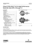
Figure 1. Type A11 Valve
and understanding the contents of this manual. If
you have any questions about these instructions,
contact your Emerson Process Management sales
office before proceeding.
Note
Introduction
Scope of Manual
This instruction manual includes installation,
maintenance, and parts information for Type A11
High Performance Butterfly Valves (figure 1) in Class
150, 300, and 600. For Class 900 and 1500 valves,
contact your Emerson Process Managementt sales
office.
For information about the actuator and accessories,
please refer to the separate instruction manuals for
these items.
Description
Type A11 High Performance Butterfly Valves are
available in either a flangeless wafer or a single
flange design, with a variety of seal, valve body, and
internal components. These valves feature a
dynamic sealing design that is used in a variety of
demanding applications.
D500073X012
Do not install, operate, or maintain a Type A11 valve
without first D being fully trained and qualified in
valve, actuator, and accessory installation,
operation, and maintenance, and D carefully reading
Neither Emerson, Emerson Process
Management, nor any of their affiliated
entities assumes responsibility for the
selection, use and maintenance of any
product. Responsibility for the
selection, use, and maintenance of any
product remains with the purchaser
and end-user.
www.Fisher.com
Instruction Manual
Form 5338
February 2007
A11 Valve
Table 1. Specifications
Seal Temperature Capabilities
Available Configurations
Valve Sizes
Class 150 and 300: Size J 30, J 36, J 42 and
J 48-inch
Class 600: Size J 3, J 4, J 6, J 8, J 10,
J 12, J 14, J 16, J 18, J 20 and J 24-inch
PTFE (Standard) Seal: For application ranges
from 62 to 232_C (80 to 450_F)
Valve Body: Wafer-style and single-flange style
in Class J 150/150, J 150, J 300, J 600,
J 900 and J 1500
High-Temperature Seals:
Standard: Metal or NOVEX to 820_C (1500_F)
Optional: 174PH H1150M to 454_C (850_F)
Phoenix III Seal: For application ranges from
73 to 232_C (100 to 450_F)
Cryogenic Seals:
CTFE: 254 to 149_C (425 to 300_F)
NOVEX: 254 to 260_C (425 to 500_F)
Maximum Inlet Pressure
Consistent with applicable ASME class
pressure/temperature ratings per ASME B16.34
unless such ratings are limited by material
temperature capabilities.
Approximate Weights
See tables 2 and 3
Construction Materials
Actuator Types Available
Refer to Bulletin 21.1:A11
J Locking-lever manual actuators, J worm-gear
manual actuators, J spring-return pneumatic
actuators, J double-acting pneumatic actuators,
and J electric actuators
Disc Rotation
Clockwise (CW) to close
ENVIRO-SEALr Packing
Valve Body Classification
This optional J PTFE or J graphite packing
system provides improved sealing, guiding, and
transmission of loading force to control liquid and
gas emissions (see figure 7). See Bulletin
59.3:041 ENVIRO-SEAL Packing Systems for
Rotary Valves for more information. Consult
factory for larger sizes; they may require a special
valve body.
Face-to-face dimensions for Type A11 valve is in
compliance with MSS SP-68 and API 609
standards.
Valve bodies are designed for installation
between standard pipe flanges: for 3 inch through
24-inch sizes (ASME B16.5); for sizes greater
than 24-inch (MSS SP-44 or API 605) as specified
on valve order
Table 2. Approximate Weight for Size 30 through 72-Inch Valves
VALVE SIZE,
INCHES
CLASS 150
Wafer
CLASS 150/150
Single Flange
Wafer
CLASS 300
Single Flange
Wafer
Single Flange
kg
30
36
42
48
528
806
1302
1904
736
1120
1550
2248
365
626
1100
1604
525
897
1328
1907
952
1315
2263
3056
1406
1989
2726
4177
54
60
66
72
2197
2790
(1)
(1)
(1)
(1)
2150
2417
3903
2893
3267
5117
(1)
(1)
(1)
(1)
lbs
30
36
42
48
1164
1778
2871
4198
1623
2470
3418
4955
805
1380
2425
3537
1157
1978
2928
4204
2100
2900
4989
6737
3100
4385
6009
9209
54
60
66
72
4844
6151
(1)
(1)
(1)
(1)
4747
5329
8604
6379
7203
11,282
(1)
(1)
(1)
(1)
1. Consult your Emerson Process Management sales office for information.
2
Instruction Manual
Form 5338
February 2007
A11 Valve
Table 3 Approximate Weight for Size 3 through 24-Inch
Valves
VALVE
SIZE
CLASS 600
Wafer Style
Single Flange
kg
3
4
6
8
10
12
14
16
18
20
24
9
10
25
52
113
153
186
274
361
526
669
15
24
48
83
163
209
254
349
481
671
880
lbs
3
4
6
8
10
12
14
16
18
20
24
20
23
54
115
249
337
410
605
796
1160
1475
32
52
106
183
360
460
560
770
1060
1480
1940
Specifications
Specifications are shown in table 1 and the
specifications for a given valve are stamped on a
nameplate attached to the valve.
Note
When installing a valve after it has
been in long-term storage, cycle the
valve at least ten times to re-energize
the dynamic seal.
Please contact your Emerson Process Management
sales office if you have any questions about
preparing a valve for storage or if you are planning
to put into service a valve that has been stored for
some time.
Adjusting the Travel Stops
CAUTION
When using manual or power
actuators, adjust the actuator travel
stops so the disc stop in the valve
body does not absorb the output of
the actuator.
For actuators without travel stops, the
actuator must be properly mounted to
prevent it from driving the valve disc
against the valve disc travel stop.
Failure to limit actuator travel as
described in this section can result in
damage to the valve shafts or other
valve parts.
Note
Installation
WARNING
Always wear protective gloves,
clothing, and eyewear when
performing any installation operations
to avoid personal injury.
Check with your process or safety
engineer for any additional measures
that must be taken to protect against
process media.
If installing into an existing
application, also refer to the WARNING
at the beginning of the Maintenance
section in this instruction manual.
An ”S” is visible on both the valve
shaft and valve body. When the valve
disc is closed, the ”S” on the shaft
aligns with the ”S” on the valve body.
1. Locate the actuator travel stop that establishes
the closed position of the valve disc. When adjusting
the travel stop make sure that the disc is from 0 to
0.76 mm (0 to 0.030 inch ) away from the internal
stop in the valve body. This adjustment is necessary
to be certain that the actuator output torque is fully
absorbed by the actuator travel stop rather than the
stop in the valve body.
For actuators without travel stops, the actuator must
be properly mounted to prevent it from driving the
valve disc against the valve disc travel stop.
3
Instruction Manual
Form 5338
February 2007
A11 Valve
1. To mount an actuator without travel stops, first, if
necessary, remove the actuator from the valve.
Then, position the valve disc from 0 to 0.76 mm (0 to
0.030 inch) away from the internal stop in the valve
body.
2. Now, travel the actuator to the maximum position.
Keep the actuator in the maximum travel position.
Return the actuator to the valve, taking care not to
disturb the position of the valve disc.
3. Mount the actuator on the valve using proper
bolts with locking washers to achieve a secure fit.
4. Before installing the valve/actuator assembly in
the process line, cycle the valve several times to be
sure the valve disc returns to the proper position.
Preparing for Installation
WARNING
If the Type A11 valve is equipped with
a fail-open actuator, remove the
actuator before installing the
valve/actuator assembly or cycle the
valve into the fully closed position.
Then, to avoid possible personal injury
or property damage, take appropriate
steps to ensure that the actuator does
not cause the valve to open during
installation.
1. If the valve and actuator have been purchased
separately or if the actuator has been removed for
storage, travel stop adjustment, or maintenance,
mount the actuator before inserting the
valve/actuator assembly into the line. Refer to the
actuator instruction manual for mounting and
adjustment procedures.
CAUTION
To avoid product damage, inspect the
valve before installation for any
damage or any foreign material that
may have collected in the valve body.
Also remove any pipe scale, welding
slag, or other foreign material from the
pipeline.
2. Remove the protective end covers from the valve
and inspect the valve body to be certain that it is free
of foreign material. Also, be certain that adjacent
pipelines are free of any foreign material, such as
4
pipe scale or welding slag that could damage the
valve seating surfaces.
WARNING
The Type A11 valve is designed for
use with the appropriate piping
schedule for the ASME class.
However, before putting the valve into
operation, measure carefully to ensure
disc rotation without interference from
piping or flanges. Be certain to center
the valve accurately to prevent
interference of the disc with the
flanges.
D The edges of a rotating disc have
a shearing effect that may result in
personal injury. To help prevent such
injuries, stay clear of the disc edges
when rotating the disc.
D Damage to the disc will occur if
any pipe flanges or piping connected
to the valve interfere with the disc
rotation path. If the piping flange has a
smaller inner diameter than specified
for schedule 80 piping, measure
carefully to be certain the disc rotates
without interference before putting the
valve into operation.
3. Select the appropriate gaskets for the application.
flexible graphite, spiral wound, or other gasket types,
made to ASME B16.5 group or user’s standard, can
be used on Type A11 valves depending on the
service conditions of the application. Note: spiral
wound gaskets, when properly centered, will cover
more than 60 percent of the gasket area at the
retaining ring screws.
For metal-seated and cryogenic valve gasket
recommendations, please contact your Emerson
Process Management sales office.
4. Refer to the appropriate table for the quantity and
size of flange bolts required (table 4 or 5) and
proceed with the following instructions.
Valve Orientation
Type A11 valve bodies are designed for installation
with the shaft in any orientation around the pipeline:
horizontal, vertical, or at an angle. However, when
installing a Type A11 valve, please follow these
recommendations.
Instruction Manual
Form 5338
February 2007
A11 Valve
Table 4. Stud Bolt and Cap Screw Data for Wafer Style Valves
Class 150 & Class 150/150
30
36
42
48
Number of Stud Bolts
VALVE SIZE, INCHES
24
28
32
40
Number of Cap Screws
8
8
8
8
Size-Diameter Inch Thread
1-1/4 8
1-1/2 8
1-1/2 8
1-1/2 8
A-Length of Stud Bolts, Inch
15-1/2
18
20-3/4
22-3/4
B-Length of Cap Screw, Inch
4-1/2
5-1/4
6
6-1/2
Class 300
30
36
42
48
Number of Stud Bolts
VALVE SIZE, INCHES
24
28
28
28
Number of Cap Screws
8
8
8
8
Size-Diameter Inch Thread
1-3/4 8
28
1-5/8 8
1-7/8 8
A-Length of Stud Bolts, Inch
21-1/2
24-1/4
26
32
B-Length of Cap Screw, Inch
5-3/4
6-1/2
7-1/4
8
Class 600
VALVE SIZE, INCHES
3
4
6
8
10
12
8
8
12
12
12
16
8
8
Size-Diameter Inch Thread
3/4 10
7/8 9
18
1-1/8 8
1-1/4 8
1-1/4 8
A-Length of Stud Bolts, Inch
7-1/4
8-1/2
10
11-1/2
13-1/2
14-3/4
B-Length of Cap Screw, Inch
4-1/4
4-1/2
14
16
18
20
24
Number of Stud Bolts
15
16
16
20
20
Number of Cap Screws
8
8
8
8
8
1-3/8 8
1-1/2 8
1-5/8 8
1-5/8 8
1-7/8 8
A-Length of Stud Bolts, Inch
16
17-1/2
19
20-3/4
22-1/4
B-Length of Cap Screw, Inch
4-1/2
5
5-1/2
5-3/4
6-1/4
Number of Stud Bolts
Number of Cap Screws
VALVE SIZE, INCHES
Size-Diameter Inch Thread
Table 5. Stud Bolt and Cap Screw Data for Single Flange Style Valves
Class 150 & Class 150/150
VALVE SIZE, INCHES
30
36
42
56
64
72
88
Size-Diameter Inch Thread
1-1/4 8
1-1/2 8
1-1/2 8
1-1/2 8
B-Length of Cap Screw, Inch
4-1/2
5-1/4
6-1/4
6-1/2
30
36
42
48
56
64
64
64
Size-Diameter Inch Thread
1-3/4 8
28
1-5/8 8
1-7/8 8
B-Length of Cap Screw, Inch
5-3/4
6-1/2
6
8-1/4
Number of Cap Screws
48
Class 300
VALVE SIZE, INCHES
Number of Cap Screws
Class 600
VALVE SIZE, INCHES
3
4
6
8
10
16
16
24
24
32
40
Size-Diameter Inch Thread
3/4 10
7/8 9
18
1-1/8 8
1-1/4 8
1-1/4 8
B-Length of Cap Screw, Inch
2-1/2
3
3-1/2
4
4-1/4
4-1/2
14
16
18
20
24
Number of Cap Screws
VALVE SIZE, INCHES
Number of Cap Screws
40
40
40
48
48
Size-Diameter Inch Thread
1-3/8 8
1-1/2 8
1-5/8 8
1-5/8 8
1-7/8 8
B-Length of Cap Screw, Inch
4-1/2
5
5-1/2
5-3/4
6-1/4
12
5
Instruction Manual
Form 5338
February 2007
A11 Valve
E0179 / IL
Figure 2. View of Stud Bolts
D In certain services (process fluids with high
concentrations of entrained solids, abrasive slurries,
or polymerizing media), valve performance will be
enhanced by installing the valve with the shaft
horizontal to the pipeline.
D Valves supplied for unidirectional shutoff should
be installed with the high pressure at the back
(waterway side) of the disc. A flow tag with an arrow
is provided for proper installation.
The High Performance Butterfly Valve is designed to
allow flow in either direction when in the open
position. When in the closed position, high pressure
should be applied to a specific side of the disc to
provide best performance and optimal service life.
D Valves supplied for bidirectional shutoff, such
as soft or Phoenix III, under normal operating
conditions can (at different times) experience
pressure in both directions; the highest of the two
pressures should be exerted on the preferred side of
the disc. If the two pressures are equal, then the one
lasting the longest period of time should be applied
to the preferred side. A flow tag with an arrow is
provided for proper installation.
If you have questions about proper valve orientation
in a specific application, contact your Emerson
Process Management sales office.
Installing the Valve
WARNING
Always wear protective gloves,
clothing, and eyewear when
performing any installation operations
to avoid personal injury.
To avoid personal injury or property
damage resulting from the sudden
release of pressure, do not install the
valve assembly where service
conditions could exceed the limits
given in this manual, the limits on the
appropriate nameplates, or the
6
matching pipe flange rating. Use
pressure-relieving devices as required
by government or accepted industry
codes and good engineering practices.
Check with your process or safety
engineer for any additional measures
that must be taken to protect against
process media.
If installing into an existing
application, also refer to the WARNING
at the beginning of the Maintenance
section in this instruction manual.
CAUTION
When ordered, the valve configuration
and construction materials were
selected to meet particular pressure,
temperature, pressure drop, and
controlled fluid conditions.
Responsibility for the safety of
process media and compatibility of
valve materials with process media
rests solely with the purchaser and
end-user. Since some valve/body trim
material combinations are limited in
their pressure drop and temperature
ranges, do not apply any other
conditions to the valve without first
contacting your Emerson Process
Management sales office.
For Wafer Style Valves:
1. See figure 3. Install the lower flange bolts first to
form a cradle for the valve.
2. Properly orient the valve according to the specific
application. Be sure the valve is placed in the line so
the flow properly enters the valve. Then, install the
valve and the gaskets between the flanges into the
cradle formed by the flange bolts.
3. Install the remaining flange bolts, making sure
that the gaskets are centered on the gasket sealing
surfaces of the flange and valve body.
4. Tighten the flange bolts in an alternating
criss-cross fashion to a torque value of one-fourth of
Instruction Manual
Form 5338
February 2007
A11 Valve
B2263/IL
Figure 3. Proper Installation Procedure
the final bolting torque. Repeat this procedure
several times increasing the torque value each time
by a fourth of the final desired torque. When the final
torque value has been applied, tighten each flange
bolt again to allow for gasket compression.
For Single Flange Valves:
1. Position the valve between the flanges. Be sure
to leave enough room for the flange gaskets; then
install the lower flange bolts.
2. Install the gaskets and align the valve and the
gaskets.
3. Install the remaining bolts.
4. Tighten the flange bolts in an alternating
criss-cross fashion to a torque value of one-fourth of
the final bolting torque. Repeat this procedure
several times increasing the torque value each time
by a fourth of the final desired torque. When the final
torque value has been applied, tighten each flange
bolt again to allow for gasket compression.
Thrust Washers
Two thrust washers are used in valve sizes 10-inch
and larger (Class 150), 8-inch and larger (Class
300), 8-inch and larger (Class 600). The thrust
washers are located at the upper and lower bearing
areas of the valve. Thrust washers must be installed
before the disc is installed in the valve body.
Packing Adjustment and Shaft Bonding
WARNING
Personal injury could result from
packing leakage. Valve packing was
tightened before shipment; however,
the packing might require some
readjustment to meet specific service
conditions. Check with your process
or safety engineer for any additional
measures that must be taken to
protect against process media.
1. For PTFE or graphite packing: Tighten
standard packing follower nuts only enough to
7
Instruction Manual
Form 5338
February 2007
A11 Valve
prevent shaft leakage. Excessive tightening of
packing will accelerate wear and could produce
higher rotating friction loads on the valve shaft. If
necessary, refer to the Packing Maintenance
section.
VALVE BODY
ACTUATOR
A
2. For ENVIRO-SEAL Packing Systems: These
packing systems will not require this initial
re-adjustment. Refer to the separate ENVIRO-SEAL
Packing System for Rotary Valves Instruction
Manual, Form 5305 for repair and adjustment
procedures.
3. For hazardous atmosphere or oxygen service
valves, read the following Warning, and provide the
bonding strap assembly mentioned below if the
valve is used in an explosive atmosphere.
WARNING
37A6528-A
A3143-2/IL
VIEW A-A
A
Figure 4. Optional Shaft-to-Body Bonding Strap
Assembly
5. Connect the other end of the bonding strap
assembly to the valve flange cap screws.
The valve drive shaft is not necessarily
grounded to the pipeline when
installed. Personal injury or property
damage could result, if the process
fluid or the atmosphere around the
valve is flammable, from an explosion
caused by a discharge of static
electricity from the valve components.
If the valve is installed in a hazardous
area, electrically bond the drive shaft
to the valve body.
Note
The packing is composed of all
conductive packing rings (graphite
ribbon packing) or partially conductive
packing rings (carbon-filled PTFE
female adaptor with PTFE V-ring
packing or graphite-composition
packing ring with PTFE/composition
packing) to electrically bond the shaft
to the valve for hazardous area
service. For oxygen service
applications, and hazardous area
service where the standard packing
doesn’t provide sufficient
shaft-to-valve body bonding, provide
alternate shaft-to-valve body bonding
according to the following step.
4. Attach the bonding strap assembly (key 131,
figure 4) to the shaft with the clamp (key 130,
figure 4).
8
6. For more information, refer to the Packing
Maintenance section below.
Maintenance
Valve parts are subject to normal wear and must be
inspected and replaced as necessary. The
frequency of inspection and replacement depends
upon the severity of service conditions.
WARNING
Avoid personal injury from sudden
release of process pressure. Before
performing any maintenance
operations:
D Disconnect any operating lines
providing air pressure, electric power,
or a control signal to the actuator. Be
sure the actuator cannot suddenly
open or close the valve.
D Use bypass valves or completely
shut off the process to isolate the
valve from process pressure. Relieve
process pressure on both sides of the
valve. Drain the process media from
both sides of the valve.
D Vent the power actuator loading
pressure.
Instruction Manual
Form 5338
February 2007
A11 Valve
D Use lockout procedures to be
sure the above measures stay in effect
while you work on the equipment.
D Always wear protective gloves,
clothing and eyewear when performing
any maintenance operations to avoid
personal injury.
D The valve packing area may
contain process fluids that are
pressurized, even when the valve has
been removed from the pipeline.
Process fluids may spray out under
pressure when removing the packing
hardware or packing rings.
D Check with your process or safety
engineer for any additional measures
that must be taken to protect against
process media.
necessary, stroke the actuator to place
the disc in the closed position while
removing the valve from the pipeline.
7. Before removing the valve from the pipeline,
make sure the valve disc is closed. See figure 3.
Rotate the shaft clockwise until the disc makes
contact with the internal stop or actuator travel stop
(if still installed). The ”S” stamped on the shaft
should be aligned with the ”S” on the valve body.
8. After removing the valve from the pipeline, move
it to an appropriate work area. Remove the actuator
from the valve.
Packing Maintenance
The Type A11 valve is designed so the shaft packing
can be replaced without removing the valve from the
process pipeline. Refer to figure 8 for available
packing configurations and figure 9 for part key
numbers.
CAUTION
When using an actuator, the actuator
travel stop (or actuator, for actuators
without adjustable stops) must be
adjusted so the disc stop in the valve
does not absorb the output of the
actuator. Failure to limit the actuator
travel can result in damage to the
valve, shaft(s), or other valve
components.
Removing the Valve
For field repair, remove the valve from the pipeline.
WARNING
Using the procedures listed in the
above WARNING, loosen the flange
bolting that holds the valve. Make sure
the valve cannot slip or twist while the
bolting is being loosened and
removed.
CAUTION
Damage to the disc can occur if the
disc is not closed when the valve is
being removed from the pipeline. If
CAUTION
The packing flange should be
tightened only enough to prevent shaft
leakage. Excessive tightening will only
accelerate wear of the packing and
could produce higher torques on the
valve.
In most cases, packing leakage can be eliminated by
merely tightening the hex nuts located above the
packing flange while the valve is in the pipeline.
However, if leakage continues, the packing must be
replaced.
1. Before loosening any parts on the valve, be sure
the pipeline has been depressurized. Then, remove
packing nuts (key 16), lift off the packing flange
(key 12) and packing follower (key 13). The packing
(key 14) is now accessible.
2. Use a packing extractor to remove packing. Insert
the corkscrew-like end of the tool into the first piece
of packing and firmly remove. Repeat this process
until all has been removed.
CAUTION
Be careful when cleaning the packing
bore. Scratches to the valve shaft
(key 4) or inside diameter of packing
bore may cause leakage.
9
Instruction Manual
Form 5338
February 2007
A11 Valve
BACK-UP
RING
GRAPHITE
GASKET
BODY
LARGEST
OUTSIDE
DIAMETER
SEAL RING
BODY
LARGEST
OUTSIDE
DIAMETER
BACK-UP
RING
METAL
SEAL
RING
RETAINING
RING
HIGH PRESSURE
AT SHUTOFF 2
VALVE DISC
VALVE DISC
SOFT SEAL WITH
BACK‐UP O‐RING
PHOENIX III
FIRE‐SAFE SEAL
BODY
RESILIENT
INSERT
HIGH PRESSURE
AT SHUTOFF 1
BODY
LARGEST
OUTSIDE
DIAMETER
LARGEST
OUTSIDE
DIAMETER
GRAPHITE
GASKET
RETAINING
RING
RETAINING
RING
VALVE DISC
METAL
SEAL
RING
HIGH PRESSURE
AT SHUTOFF 1
VALVE DISC
CRYOGENIC
SEAL RING
HIGH PRESSURE
AT SHUTOFF 1
CRYOGENIC SEAL
NOVEX METAL SEAL
NOTES:
1 THIS UNIDIRECTIONAL SEAL MUST BE INSTALLED SO THAT THE RETAINING
RING IS DOWNSTREAM FROM THE HIGH PRESSURE SIDE OF THE VALVE AT
SHUTOFF, AS SHOWN.
2 FOR THIS BIDIRECTIONAL SEAL, THE “PREFERRED” VALVE ORIENTATION
PLACES THE RETAINING RING DOWNSTREAM FROM THE HIGH PRESSURE SIDE
OF THE VALVE AT SHUTOFF.
E0578 / IL
Figure 5. Seals
3. Before installing new packing, clean the packing
bore.
bodies. They are normally either 1/8 inch NPT or 1/4
inch NPT.
4. Install new packing one ring at a time, using the
packing follower as a driver. If split packing is used,
stagger seams every 90_.
Seal Maintenance
5. Reinstall the packing follower and packing flange,
secure nuts, and tighten as needed.
Lantern Rings
Valves only have lantern rings if they are provided
with purge fittings or lubrication fittings. Lantern rings
are located either at the bottom of the packing or
central packing area as noted in figure 8.
Lubrication Fittings and Purge
Connectors
These connections and/or fittings are located on the
lower gasket retainer and packing area of valve
10
1. After the valve has been removed from the line
and the manual or power actuator has been
removed, manually rotate the shaft (key 4)
counter-clockwise until the disc has moved a
full 180_. Note that the ”S” on the shaft is 180_ from
the ”S” on the valve body.
2. Lay the valve flat on a work bench in a secure
position with the retaining ring (key 2) and retaining
ring screws (key 22) facing up. Use blocks or other
appropriate techniques to support the valve.
Remove all retaining ring screws.
3. Remove the retaining ring by placing a retaining
ring screw in each of the two retaining ring jack
screw holes. With the appropriate tool, slowly rotate
the screws until the retaining ring has been lifted
from the valve body.
Instruction Manual
Form 5338
February 2007
A11 Valve
CAUTION
In the following step, use the
appropriate tool to avoid damage to
the seal or T-slot area of the valve.
4. Different valve types have different seal designs
and components. To see the appropriate seal, refer
to figure 5. Insert the appropriate tool under the top
edge of seal and gently pry the seal out. Take care
not to damage the seal or T-slot area of the valve
body. After the seal has been removed, clean the
T-slot area, retaining ring and, if required, polish the
disc thoroughly with fine steel wool or other
appropriate material.
4. When the seal is thoroughly seated, re-install the
retaining ring and screws. Tighten the retaining
screws just enough to eliminate vertical movement
of the retaining ring. With the use of the blunt end
tool, carefully tuck the lip of the seal ring under the
retaining ring.
5. When the seal is under the lip of the retaining
ring, tighten the screws according to standard
procedures. Manually rotate the valve shaft
clockwise 180_ to return the disc to its closed
position against the internal stop.
6. The final seating of the retaining ring screws can
now be done. For the screw torque values, refer to
table 6. The seal is now fully installed and the valve
may be closed for installation or storage.
Soft Seal Installation
1. Locate the replacement seal ring (key 8) and note
the shape of the ring. The ring is wider across one
edge diameter and narrower across the other edge
diameter as shown in figure 6. Around the outside
circumference is one wide groove.
Before installing the seal ring into the valve body, the
backup ring (key 9) must first be placed onto the
wide, outer groove of the seal ring.
2. The seal ring and backup ring assembly must be
installed in the valve. The wider outside diameter of
the seal ring goes into the T-slot area of the valve
body, shown in figure 7. Start the wider diameter
edge of the seal ring into the T-slot of the valve body
using a blunt end screwdriver.
3. Carefully tuck the backup ring downward into the
valve body T-slot until the seal ring and back-up ring
are completely entrapped in the valve body T-slot.
Metal and Phoenix III Seal Installation
For metal seal installation:
Locate the replacement seal ring (key 8) and note
the shape of the ring. The ring is wider across one
edge diameter and narrower across the other edge
diameter as shown in figure 6. Around the outside
circumference is one wide groove.
Install the seal ring (key 8) into the valve body by
first placing the wider outside diameter of the seal
ring into the T-slot area of the valve body which is
shown in figure 7. Metal seals without a back-up ring
will fall into place. Metal seals with a back-up ring
(key 9) will have to be installed following the
instructions given below for the Phoenix III seal with
back-up ring.
11
Instruction Manual
Form 5338
February 2007
A11 Valve
Figure 6. Typical Seal Ring (Sectional)
opening between the valve body and the seal ring.
Use the seal tool to apply pressure to the backup
ring and carefully tuck the backup ring down into the
T-slot between the valve body and the seal ring.
Note: On larger valves, it may be more efficient to
have someone hold down the seal ring while the
backup ring is pushed into the T-slot.
3. Once the seal ring or seal and backup ring has
been fully installed into the valve body T-slot, the
retaining ring gasket (key 17) can be installed.
CAUTION
A5251/IL
Figure 7. Typical Seal Installation
For Phoenix III seal installation:
1. Locate the replacement seal ring (key 8) and note
the shape of the ring. The ring is wider across one
edge diameter and narrower across the other edge
diameter as shown in figure 6. Around the outside
circumference is one wide groove.
Install the seal ring in the valve body by first placing
the wider outside diameter of the seal ring, as
marked in figure 6, into the T-slot area of the valve
body which is shown in figure 7. Phoenix III seal
rings without a back-up ring will fall into place. If the
Phoenix III seal uses a back-up ring (key 9), the
back-up ring will have to be installed after placing
the seal ring in the valve using a blunt end
screwdriver. Do not use the screwdriver or seal tool
directly on the metal seat. Use a tool only on the
backup ring.
2. With the seal ring inserted all the way around the
valve body T-slot now lay the backup ring into the
12
This gasket is a thin graphite material.
Take care to avoid damaging the
gasket. However, punch one initial
screw hole through the gasket for
alignment purposes.
4. Install the retaining ring and align the screw holes
in the retaining ring with the holes in the valve body.
Install the first retaining ring screw through the
punched hole in the ring gasket. Install the other ring
screws by pushing the screws through the graphite
gasket and threading them into valve body.
5. Tighten the retaining ring screws just enough to
eliminate vertical movement of the retaining ring. Do
not tighten the retaining ring screws.
WARNING
Avoid personal injury or property
damage caused by the impact of a
falling or tipping large valve. Large
valves must be properly supported
during maintenance.
6. To complete this step, stand the valve up.
Support the valve securely using methods
appropriate for the valve size.
Instruction Manual
Form 5338
February 2007
A11 Valve
CAUTION
If a vise or other clamps are being
used, be sure damage is not done to
the flange gasket sealing area of the
valve body.
7. Manually rotate the valve shaft to turn the disc
clockwise to meet the seal.
8. Tap the disc with a rubber mallet to drive it
against the internal travel stop. When the disc
makes contact with the stop, manually rotate the
disc counter-clockwise back out of the seal to a 90_
open position. Repeat steps 7 and 8 three times.
9. The final seating of the retaining ring screws can
be done. For the screw torque values, refer to
table 6. The seal is now fully installed and the valve
may be closed for installation or storage.
Cryogenic Seal Installation
1. Locate the replacement seal ring (key 8) and note
the shape of the ring. The ring is wider across one
edge diameter and narrower across the other edge
diameter as shown in figure 6. Around the outside
circumference is one wide groove.
For Kel-F seals with aluminum backup rings
only: Now, locate the replacement V-ring. Please
notice that the V-ring is similar in diameters to the
seal ring. Place the V-ring down onto the seal ring
with the larger diameter of the V-ring going first. Be
sure the larger diameters on both rings are down.
2. For all types: Install the seal ring (or seal ring
and V-ring) in the valve body by first placing the
wider outside diameter of the seal ring into the T-slot
area of the valve body. The seal ring with or without
a back-up ring will fall into place.
3. Once the seal ring (or seal ring and V-ring) have
been fully installed into the valve body T-slot, the
retaining ring gasket can be installed.
4. Install the retaining ring and align the screw holes
in the retaining ring with the holes in the valve body.
Install the first retaining ring screw through the
punched hole in the ring gasket. Install the other ring
screws by pushing the screws through the graphite
gasket and threading them into the screw holes in
the valve body.
5. Tighten the retaining ring screws just enough to
eliminate vertical movement of the retaining ring. Do
not tighten the retaining ring screws.
WARNING
Avoid personal injury or property
damage caused by the impact of a
falling or tipping large valve. Large
valves must be properly supported
during maintenance.
6. To complete this step, stand the valve up.
Support the valve securely using methods
appropriate for the valve size.
CAUTION
If a vise or other clamps are being
used, be sure damage is not done to
the flange gasket sealing area of the
valve body.
7. Manually rotate the valve shaft to turn the disc
clockwise to meet the seal.
8. Tap the disc with a rubber mallet to drive it
against the internal travel stop. When the disc
makes contact with the stop, manually rotate the
disc counter-clockwise back out of the seal to a 90_
open position. Repeat steps 7 and 8 three times.
9. The final seating of the retaining ring screws can
be done. For the screw torque values, refer to
table 6. The seal is now fully installed and the valve
may be closed for installation or storage.
Valve Shaft/Disc Pin Unit Maintenance
CAUTION
This gasket is a thin graphite material.
Take care to avoid damaging the
gasket. However, punch one initial
screw hole through the gasket for
alignment purposes.
Valve Shaft/Disc Pin Unit Removal
1. Rotate the disc (key 3) 180_ counterclockwise
from the full closed position.
2. Place the open valve horizontally on a suitable
work surface with the retaining ring (key 2) facing
upward. Be sure to properly support the valve with
blocks while the shaft is being removed.
13
Instruction Manual
Form 5338
February 2007
A11 Valve
A5249/IL
Figure 8. Packing Configurations
Note
The disc must be removed from the
waterway side of the valve body, which
is the side opposite the T-slot area.
Support the valve and disc so the disc
can be easily removed from the valve
when the shaft is removed.
3. Use a pin extractor to remove the disc pins
(key 6). Select the proper pin extractor tip with
screws of proper thread size to match the thread
size in the disc pins.
4. Screw the pin extractor tip into the pin as far as
possible. With an upward, straight sliding motion,
extract the pin. Repeat the same procedure for the
other pins.
A threaded rod with an appropriate spacer and nut
can also be used as an extractor tool. If using a
threaded rod, choose a rod with threads that fit the
inside threads of the pins. The rod should extend
14
several inches above the disc when screwed into a
pin.
5. After screwing the rod into the pin, slide the
spacer over the rod and pin. Thread the nut onto the
rod and tighten. As the nut is tightened, it will drive
the spacer against the disc and the increasing
pressure will draw the pin from the disc.
6. Loosen the packing nuts (key 16).
7. Extract the shaft (key 4) by hand-pulling or by
using the pin extractor screwed into the end of the
shaft.
Note
Valves with a two-piece shaft use a
gasket retainer, which must be
removed before removing the lower
shaft.
Instruction Manual
Form 5338
February 2007
A11 Valve
Table 6. Torque Values for Fasteners
Fastener
Nominal Size
NSm
InSlb
FtSlb
#10
4
35
---
1/4
9
81
---
5/16
19
167
---
3/8
33
295
---
7/16
53
---
39
1/2
80
---
59
9/16
117
---
86
5/8
161
---
119
3/4
286
---
211
7/8
447
---
330
1
651
---
480
1-1/8
837
---
617
CAUTION
In the following step, remove the disc
from the waterway side of the valve to
avoid damage to the disc or T-slot area
of the valve.
8. Remember: the disc must be removed from the
waterway side of the valve. Do not try to force the
disc through the seal side of the valve. This could
cause severe damage to the disc and T-slot area.
After removing the shaft, remove the disc.
Valve Shaft/Disc Pin Unit Installation
Note
Replacement disc and shaft(s) are
provided as a matched set. When
replacing either the disc or shaft(s), a
matched set is required.
To replace the disc pin assembly (key 6), reverse
the removal steps used above.
Before placing disc into a valve body, properly align
the top of the disc with the top of the valve. A ”T” is
stamped on the disc to indicate alignment. Be sure
holes in the shaft are exactly aligned with the holes
in the disc before re-installing pins. After pins are
fully seated in the disc, use a punch or small chisel
to stake the pins at three points. This will prevent the
pins from working free and out of the disc due to
vibration.
Gasket Retainer
When two-piece shafts are used, a gasket retainer
assembly must be used. The gasket is held in place
by a gasket retainer and four hex head bolts and
lockwashers. When re-assembling the valve, this
gasket should always be replaced. Be sure the
gasket is centered over the shaft bore before
retightening bolts. Tighten down bolts evenly in a
cross over pattern or in a star pattern. Refer to table
6 for proper torque values.
Bearing Maintenance
Bearing Removal
To get access to the bearings (key 10), the disc and
shaft assembly (keys 3, 4 and 5) must be removed
from the valve. The bearings (key 10) may be
removed by using a brass drift punch and lightly
tapping them out. In valves without lower bonnets,
the lower bearing is removed by grasping it and
pulling upwards. Also, cryogenic valves have an
outboard bearing under the packing. Refer to the
Packing Maintenance section for instructions.
Bearing Installation
Before installation of the bearings, bearing bores
should be solvent cleaned and bearings will slip in.
15
Instruction Manual
Form 5338
February 2007
A11 Valve
16
PACKING HEX NUTS
12
PACKING FLANGE
4
SHAFT, UPPER
14
PACKING SET
13
PACKING
FOLLOWER
15
PACKING
STUDS
22
SOCKET HEAD CAP OR
RETAINING RING SCREWS
9
BACK-UP RING
8
SEAL RING
2
RETAINING RING
17
GASKET
1
BODY
10
BEARING
1
6
SHAFT/DISC PINS
3
VALVE DISC
5
LOWER (FOLLOWER)
SHAFT
10
BEARING
NOTE:
1 REQUIRED FOR FIRE SAFE, METAL SEATED AND CRYOGENIC VALVES.
E0574 / IL
Figure 9. Typical Type A11 Valve Assembly
Parts Ordering
When corresponding with your Emerson Process
Management sales office about a Type A11 valve,
please mention the valve serial number which is
stamped on the nameplate and the part number from
the following list.
WARNING
Use only genuine Fisherr replacement
parts. Components that are not
supplied by Emerson Process
Management should not, under any
16
circumstances, be used in any Fisher
valve, because they will void your
warranty, might adversely affect the
performance of the valve, and could
give rise to personal injury and
property damage.
Note
Neither Emerson, Emerson Process
Management, nor any of their affiliated
entities assumes responsibility for the
selection, use and maintenance of any
product. Responsibility for the
selection, use, and maintenance of any
product remains with the purchaser
and end-user.
Instruction Manual
Form 5338
February 2007
A11 Valve
Parts List
All items listed as being 3 through 24-inch are for the
Class 600 valves only. The 30 through 48-inch items
are for 150/150, 150 or 300 Class valves, as
specified.
Key
Description
17*
Gasket (Retainer Ring) w/Metal and Phoenix III Seals (cont)
24-inch
V164220X012
30-inch Class 150
V168292X012
30-inch Class 150/150
V124868X012
30-inch inch Class 300
V124882X012
36-inch Class 150 & 150/150
V124869X012
36-inch Class 300
V124883X012
42-inch Class 150 & 150/150
V124872X012
42-inch Class 300
V124881X012
48-inch Class 150 & 150/150
V125088X012
48-inch Class 300
V124874X012
Oxygen Service
3-inch
V163883X022
4-inch
V164130X022
6-inch
V163884X022
8-inch
V168656X012
10-inch
V164111X022
12-inch
V164217X022
14-inch
V139619X042
16-inch
V164218X022
30-inch Class 150
V168292X022
30-inch Class 150/150
V124868X022
30-inch Class 300
V124882X022
36-inch Class 150 & 150/150
V124869X022
36-inch Class 300
V124883X022
42-inch Class 150 & 150/150
V124872X022
42-inch Class 300
V142881X022
48-inch Class 150 & 150/150
V125088X022
48-inch Class 300
V124874X022
Gasket Retainer (Not Shown)
8-inch
V112278X012
10-inch
V110620X012
12-inch
V110621X012
30 & 36-inch
V111679X012
42-inch
V139469X012
48-inch
V121625X012
Retainer Gasket (not shown)
See following table
Lockwasher, retaining ring assembly S31600
Lockwasher, packing assembly
Hex Head Bolt (Not Shown)
Socket Head Cap or Retaining Ring Screws
Nameplate (Not shown)
Packing Spacer (Not shown)
Drive Screw (Not Shown)
Disc/Shaft Assembly
See following table
Label
Flow Arrow (Not Shown)
Line Bolting
Note
Part numbers are shown for recommended spares
only. For other part numbers, contact your Emerson
Process Management sales office.
Key
1
Description
Part Number
Valve Body
If you need a valve body as a replacement part, order the
valve size, Class, serial number, and desired material.
Contact your Emerson Process Management sales office.
2
7*
Retaining Ring
Key (Not Shown)
6-inch
V116663X012
8- & 10-inch
V116663X012
12-inch
V116197X012
30- & 36- inch Class 150/150
V171330X012
42-inch Class 150/150, 30-, 36- & 48-inch
Class 150 & 30-inch Class 300
13B2601X012
36-inch Class 300
13B3422X012
42-inch Class 150
V148564X012
42-inch Class 300
V178488X012
Seal Ring
See following table
Back-up Ring
Bearing
See following table
Thrust Bearing (Not Shown)
See following table
Packing Flange
Packing Follower
Packing Set
See following table
Stud
Hex Nut
Gasket (Retainer Ring) w/Metal and Phoenix III Seals
3-inch
V163883X012
4-inch
V164130X012
6-inch
V163884X012
8-inch
V168656X022
10-inch
V164111X012
12-inch
V164217X012
14-inch
V164128X012
16-inch
V164218X012
18-inch
V164129X012
20-inch
V163952X012
8*
9
10*
11*
12
13
14*
15
16
17*
*Recommended spare parts
18*
19*
20
20
21
22
24
26
27
28*
29
33
---
Part Number
17
Instruction Manual
Form 5338
February 2007
A11 Valve
ENVIRO-SEALr Packing Parts
Key
Description
Parts shown are used in standard and NACE constructions.
100
Stud
101
Hex Nut
102
Packing Flange
103
Spring Pack
105* Packing Set
Use w/PTFE packing
3-inch
12B9122X012
4-inch
12B7414X012
6-inch
12B9078X012
8-inch
12B7462X012
10-inch
13B9155X012
12-inch
14B3647X012
14-inch
12B7782X012
16-inch
14B5652X012
18-inch
14B5730X012
Use w/Graphite packing
3-inch
13B8816X022
4-inch
13B8816X052
6-inch
13B8816X102
8-inch
13B8816X142
10-inch
14B3541X032
12-inch
14B3541X052
14-inch
14B3541X042
16-inch
14B3541X062
18-inch
14B3541X072
106*
Anti-Extrusion Ring (2 req’d)
Use w/PTFE packing
3-inch
4-inch
6-inch
8-inch
10-inch
12-inch
14-inch
16-inch
18-inch
Packing Box Ring
Tag
Cable Tie
Lubricant
18
107
111
112
113
*Recommended spare parts
Part Number
12B9121X012
12B7418X012
12B9084X012
12B7466X012
13B9159X012
14B3642X012
12B7783X012
14B5656X012
14B5734X012
Instruction Manual
Form 5338
February 2007
A11 Valve
Key 8* Seal Ring
VALVE SIZE,
INCHES
MATERIAL
CLASS
ETFE
Metal Seal Ring S31600
Metal Seal Ring S17400
H1150M
Phoenix III Metal Seal
Ring
3
V111012X012
V110605X012
V110605X022
V114478X012
4
V111035X012
V149609X012
V149609X022
V114480X012
6
V118868X012
V118864X012
V118864X022
V119985X012
8
V111037X012
V141699X012
V141699X022
V142361X012
10
V111038X012
V148798X012
V148798X022
V143266X012
V111039X012
V149262X012
V149262X022
V143160X012
14
V111979X012
V111992X012
V111992X022
V114495X012
16(1)
V130804X012
V135726X012
V149048X012
18
V111985X012
V149399X012
V149399X022
V114501X012
20
V111988X012
V111995X012
V111995X022
V149319X012
24
V111991X012
V111996X012
V111996X022
V114509X012
12
600
42
150/150
13B1554X012
42
150
13B1571X012
48
150/150
13B1555X012
48
150
13B1572X012
MATERIAL
VALVE SIZE,
INCHES
CLASS
30
30
PTFE
NOVEX
Phoenix III Metal Seal
Ring
Phoenix III Metal Seal
Ring for Oxygen Service
150/150
V113145X012
V161260X012
V114471X012
V114471X022
150
V113350X012
V159048X022
V114472X012
V114472X022
30
300
V113353X012
13B2252X042
V114473X012
V114473X022
36
150/150
V113355X012
V143195X012
V114474X012
V114474X022
36
150
V113358X012
V159051X012
V143197X012
V143197X012
36
300
V113361X012
13B3645X012
V141335X012
V141335X022
42
150/150
V130753X012
V126141X012
V126141X022
42
150
V130775X012
V127525X012
V127525X022
42
300
V130093X012
V130184X012
V130184X022
48
150/150
V130772X012
V119520X012
V119520X022
48
150
V136069X012
V129715X012
V129715X022
48
300
V130445X012
13B2032X012
13B2032X022
1. The part number for 16-inch, Metal Seal Ring S31600/ETFE is V161370X012
*Recommended spare parts
19
Instruction Manual
Form 5338
February 2007
A11 Valve
Keys 10* and 11* Bearing and Thrust Bearing
VALVE SIZE,
INCHES
CLASS
QUANTITY
BEARING MATERIAL
PEEK
S31600
Bronze
Alloy 6
Key 10 Bearing
3
3
13B1509X012
V110614X022
V110614X022
V110614X042
4
3
13B1660X012
V166684X012
V166684X032
V166684X052
6
3
13B1489X012
V168505X012
V168505X022
V168505X052
8
4
13B1851X012
V174342X012
V174342X022
V174342X042
10
4
13B1738X012
V110616X012
V110616X022
V110616X042
4
V168186X012
V171724X012
V171724X032
V171724X042
14
4
V168187X012
V170455X012
V170455X032
---
16
4
V168188X012
V1316999X052
V131699X032
---
18
4
V168189X012
V131703X042
V131703X052
---
20
6
13B1973X012
V112012X012
V112012X022
---
24
4
13B2776X012
V112014X012
V112014X022
---
12
600
30
150/150
4
V127742X032
13B1585X012
V127742X042
V127742X052
30
150
4
V167654X012
V171363X012
V131010X012
V131010X042
30
300
4
13B1968X012
V175126X012
V175126X032
V175126X042
36
150/150
4
13B1969X012
V176032X012
V176032X032
V176032X022
36
150
4
13B1970X012
V171361X012
V171361X032
V171361X052
36
300
4
13B1971X012
V174912X042
V174912X032
V174912X012
42
150/150
4
13B1972X012
V114716X012
V114716X022
V114716X052
42
150
6
13B1973X012
V112012X012
V112012X022
V112012X052
42
300
6
13B1974X012
V130181X012
V130181X042
V130181X032
48
150/150
6
13B1768X012
V171361X012
V171361X032
V171361X052
48
150
4
13B1975X012
V171365X012
V171365X032
V171365X052
48
300
10
13B1976X012
V117028X012
V117028X042
V117028X032
Key 11 Thrust Bearing
8
2
13B1850X012
V174343X012
V174343X022
V174343X052
10
2
13B1739X012
V110446X012
V110446X022
V110446X042
12
2
V168181X012
V131681X022
V131681X042
V131681X052
14
2
13B2777X012
V127739X032
V127739X042
---
2
13B2778X012
V137374X032
V137374X012
---
18
2
13B2779X012
V112445X022
V112445X012
---
20
2
13B2780X012
V112016X012
V112016X022
---
24
2
13B2781X012
V157177X022
V157177X012
---
150/150
2
13B1584X012
V171360X012
V171360X022
V171360X042
150
2
V167656X012
V171364X012
V171364X022
V171364X042
300
2
13B1959X012
V175127X012
V175127X022
V175127X042
150/150
2
13B1960X012
V136767X022
V136767X032
V136767X042
150
2
13B1961X012
V171362X012
V171362X022
V171362X052
300
2
13B1962X012
V116148X012
V116148X022
V116148X052
150/150
2
13B1963X012
V125303X012
V125303X022
V125303X052
150
2
13B1964X012
V137636X012
V137636X042
V137636X052
300
2
13B1965X012
V130097X012
V130097X032
V130097X042
150/150
2
13B1769X012
V113699X012
V113699X042
V113699X032
150
2
13B1966X012
V151148X012
V151148X042
V151148X052
300
2
13B1967X012
V117029X012
V117029X032
V117029X042
16
30
36
42
48
20
600
*Recommended spare parts
Instruction Manual
Form 5338
February 2007
A11 Valve
Key 14* Packing Set
VALVE SIZE, INCHES
CLASS
MATERIAL
PTFE V-Ring
Graphite
Graphite with Oxygen Service
3
V113124X022
V113124X012
V113124X032
4
V113128X022
V113128X012
V113128X032
6
V111025X022
V111620X012
V111025X032
8
V110456X012
V110456X022
V110456X032
10
V111028X032
V111028X012
V111028X022
V111696X032
V111696X012
V111696X022
14
V111442X032
V111442X012
V111442X022
16
V111705X032
V111705X012
V111705X022
18
V111709X032
V111709X012
V111709X022
20
V125909X022
V125909X012
24
V112041X012
V112041X022
12
600
30
150/150
V111699X012
V111442X012
V111442X022
30
150
V111704X012
V111705X012
V111705X022
30
300
V121593X012
V115138X012
V115138X022
36
150/150
V117210X012
V116838X012
V116838X022
36
150
V121811X012
V129596X012
V129596X022
36
300
V122149X012
V115155X012
V115155X022
42
150/150
V114721X012
V126139X012
V126139X022
42
150
V112038X012
V112039X012
V112039X022
42
300
V130100X012
V147154X012
V147154X022
48
150/150
V119322X012
V115058X012
V115058X022
48
150
V126979X012
V119524X012
V119524X022
48
300
V130450X012
V147480X012
V147480X022
*Recommended spare parts
21
Instruction Manual
Form 5338
February 2007
A11 Valve
Key 19* Retainer Gasket (not shown)
MATERIAL
VALVE SIZE, INCHES
22
CLASS
Standard Service
Soft Seal
Standard Service
Metal/Phoenix III Seal
Oxygen Service
with Soft or Metal Seals
8
V135212X022
V135212X012
V135212X032
10
V135209X022
V135209X012
V135209X032
12
V148910X032
V148910X012
V148910X022
14
V139619X022
V139619X012
V139619X032
16
V112057X012
V112057X022
V112057X032
18 & 20
V112058X012
V112058X022
24
V144925X012
V144925X022
600
30
150/150
V124603X022
V124603X012
V124603X032
30
150
V135139X022
V135139X012
V135139X032
30
300
V148908X022
V148908X012
V148908X032
36
150/150
V135139X022
V135139X012
V135139X032
36
150
V135138X022
V135138X012
V135138X032
36
300
V148909X022
V148909X012
V148909X032
42
150 & 150/150
V135211X022
V135211X012
V135211X032
42
300
V147155X022
V147155X012
V147155X032
48
150/150
V135138X022
V135138X012
V135138X032
48
150
V148908X022
V148908X012
V148908X032
48
300
V171283X022
V171283X012
V171283X032
*Recommended spare parts
Instruction Manual
Form 5338
February 2007
A11 Valve
Key 28*, Disc-Shaft-Pin Assembly(1) Square Connection [Disc (key 3), Shaft (key 4), Follower Shaft (key 5), and Pin (key 6)]
VALVE SIZE, INCHES
3
4
6
8
10
12
SHAFT MATERIAL(2)
DISC MATERIAL
CF8M Chrome Coated
CF8M ENC
CF8M Hard Face
S17400 H1025
V138800X092
V138800X022
V138800X032
N05500
V138800X112
V138800X052
V138800X142
S17400 H1150M
V138800X102
V138800X012
V138800X152
S17400 H1025
V161632X082
V161632X042
V161632X022
N05500
V161632X102
V161632X012
V161632X122
S17400 H1150M
V161632X092
V161632X152
V161632X142
S17400 H1025
V161647X092
V161647X052
V161647X042
N05500
V161647X122
V161647X132
V161647X022
S17400 H1150M
V161647X102
V161647X012
V161647X152
S17400 H1025
V145082X102
V145082X012
V145082X062
N05500
V145082X122
V145082X052
V145082X142
S17400 H1150M
V145082X112
V145082X032
V145082X152
S17400 H1025
V126325X082
V126325X012
V126325X032
N05500
V126325X102
V126325X052
V126325X152
S17400 H1150M
V126325X092
V126325X042
V126325X062
S17400 H1025
V126329X042
V126329X012
V126329X032
N05500
V126329X062
V126329X112
V126329X122
S17400 H1150M
V126329X052
V126329X132
V126329X142
1. Part numbers provided in this table are assembly numbers including keys 3, 4, 5 and 6. The pin (key 6) is listed as a spare part and can be ordered without the assembly.
2. The same shaft material is used in one or two shaft valve assemblies.
Key 28*, Disc-Shaft-Pin Assembly(1) Keyed Connection [Disc (key 3), Shaft (key 4), Follower Shaft (key 5), and Pin (key 6)]
VALVE SIZE, INCHES
30
Class 150
36
Class 150
SHAFT MATERIAL(2)
DISC MATERIAL
CF8M
CF8M ENC
CF8M Chrome Coated
S17400 H1025
13B3474X022
13B3474X102
13B3474X062
N05500
13B3474X212
13B3474X222
13B3474X172
S17400 H1150M
13B3474X152
13B3474X162
13B3474X052
S17400 H1025
13B3529X042
13B3529X062
13B3529X022
N05500
13B3529X172
13B3529X182
13B3529X192
S17400 H1150M
13B3529X102
13B3529X122
13B3529X132
1. Part numbers provided are assembly numbers including keys 3, 4, 5 and 6. The pin (key 6) is listed as a spare part and can be ordered without the assembly.
2. The same shaft material is used in one or two shaft valve assemblies.
*Recommended spare parts
23
Instruction Manual
Form 5338
February 2007
A11 Valve
ENVIRO-SEAL and Fisher are marks owned by Fisher Controls International LLC, a member of the Emerson Process Management business division of Emerson Electric Co. Emerson and the Emerson logo are trademarks and service marks of Emerson Electric Co. All other marks are the
property of their respective owners.
The contents of this publication are presented for informational purposes only, and while every effort has been made to ensure their accuracy, they
are not to be construed as warranties or guarantees, express or implied, regarding the products or services described herein or their use or applicability.
We reserve the right to modify or improve the designs or specifications of such products at any time without notice.
Neither Emerson, Emerson Process Management, nor any of their affiliated entities assumes responsibility for the selection, use and
maintenance of any product. Responsibility for the selection, use and maintenance of any product remains with the purchaser and end-user.
Emerson Process Management
Marshalltown, Iowa 50158 USA
Cernay 68700 France
Sao Paulo 05424 Brazil
Singapore 128461
www.Fisher.com
24
EFisher
Controls International LLC 1992, 2007; All Rights Reserved
Printed in USA