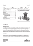
1
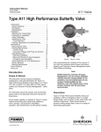
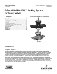
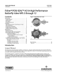
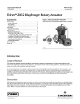
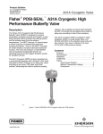
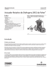
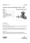
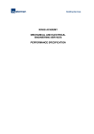
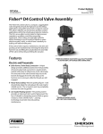
Product Bulletin A31D Valve 21.1:A31D September 2014 D500213X012 Fisherr POSI-SEALt A31D Double-Flange High-Performance Butterfly Valve The Fisher A31D double-flange high-performance butterfly valve provides outstanding performance under extreme pressure and temperature conditions. The A31D valve is available with face-to-face dimensions conforming to ISO 5752 Butterfly Valve Short (CL150) or Long (CL300) Series (for other face-to-face dimension requirements, consult your Emerson Process Management sales office). A splined shaft combines with a variety of Fisher spring-and-diaphragm or pneumatic piston actuators. A keyed drive shaft combines with a variety of handlevers, handwheels, or pneumatic double-acting or spring-return piston actuators. These combinations make the A31D valve a reliable, high-performance butterfly valve for both throttling and on-off applications in the process industries. The A31D valve can be supplied with one of several dynamic seals (figure 1) that can be used in a variety of demanding applications. With the appropriate seal selection and materials of construction, the pressure-assisted seal provides excellent shutoff against the full ASME class pressure range. Features Excellent Shutoff Integrity-- The pressure-assisted seal design provides tight shutoff and permits the use of smaller actuators in applications requiring full ASME B16.34 shutoff capabilities. True Bi-directional Shutoff Performance-- A31D valve design helps to ensure that the torque necessary to open and close the valve is the same regardless of the direction in which the differential pressure is applied. www.Fisher.com X0704 Fisher A31D Valve with 2052 Actuator Safety-- Shaft-blowout protection is designed into the A31D valve (figure 2). For NPS 3 through 12 valves, the packing follower and an anti-blowout follower hold an anti-blowout gland securely around the valve shaft. Under the anti-blowout gland, a formed wire ring around the shaft completes the protection design. For NPS 14 through 24 valves, the anti-blowout gland fits securely over the valve shaft which has been turned down to form a circumferential shoulder that contacts the anti-blowout gland. Product Bulletin A31D Valve 21.1:A31D September 2014 D500213X012 Excellent Emissions Capabilities-- The optional ENVIRO-SEAL™ packing system is designed with improved sealing, guiding, and loading force transmission. The ENVIRO-SEAL packing system can control emissions to below the EPA (Environmental Protection Agency) limit of 100 ppm (parts per million) for valves. Sour Service Capability-- Trim and bolting materials are available for applications involving sour liquids and gases. These constructions comply with NACE MR0175-2002, MR0103, and MR0175/ISO 15156. Reliable Flange Gasketing Surface-- Seal retainer screws are located so there is no interference with the sealing function of either flat sheet or spiral wound line flange gaskets. Shaft Versatility-- This valve will meet your actuator needs with a choice of splined or keyed shaft connections. Easy Installation-- The valve body self-centers on the line flange bolts as a fast, accurate means of centering the valve in the pipeline. Table of Contents Features . . . . . . . . . . . . . . . . . . . . . . . . . . . . . . . . . . . . . Specifications . . . . . . . . . . . . . . . . . . . . . . . . . . . . . . . . Installation . . . . . . . . . . . . . . . . . . . . . . . . . . . . . . . . . . Standard Seal Configurations . . . . . . . . . . . . . . . . . . . 2 1 3 4 4 Tables Materials of Construction and Temperature Ranges 6 Valve Body Material Pressure/Temperature Ratings . . . . . . . . . . . . . . . . . . . . . . . . . . . . . . . . . . . 8 Dimensions and Weights . . . . . . . . . . . . . . . . . . . . . . 10 Product Bulletin A31D Valve 21.1:A31D September 2014 D500213X012 A31D Valve Specifications and Materials of Construction Table 1. Fisher A31D Valve Specifications SPECIFICATION Valve Body Size NPS 3, 4, 6, 8, 10, 12, 14, 16, 18, 20, and 24 Pressure Rating Consistent with CL150 and 300 per ASME B16.34(1) Valve Body Materials WCC Steel CF8M Stainless Steel Disk Materials CF8M Stainless Steel End Connections Mates with RF flanges per ASME B16.5 Valve Body Style Shaft Connection Face-to-Face Dimensions Double Flange Spline (standard) Keyed (optional) CL150: ISO 5752 Butterfly Valve Short Series CL300: ISO 5752 Butterfly Valve Long Series Soft Seal: Bidirectional ANSI/FCI 70-2 Class VI Shutoff NOVEX Seal: Unidirectional MSS SP-61(2) Flow Direction Reverse (flow direction is into the shaft side of the disk) Phoenix III Seal: ANSI/FCI 70-2 Class VI Flow Characteristic Approximately Linear Disk Rotation Clockwise (CW) to close 1, See table 4 and figure 4 for additional information. The pressure/temperature limits in this bulletin and any applicable codes or standard limitation should not be exceeded. 2. 0.1 scfh per unit of NPS at 80 psi. 3 Product Bulletin A31D Valve 21.1:A31D September 2014 D500213X012 Figure 1. Available Seal Configurations BACK-UP RING BODY SEAL RING GRAPHITE GASKET LARGEST OUTSIDE DIAMETER BACK-UP RING BODY LARGEST OUTSIDE DIAMETER SEAL RING RETAINING RING VALVE DISC HIGH PRESSURE AT SHUTOFF 2 VALVE DISC SOFT SEAL WITH BACK-UP O-RING PHOENIX III FIRE-TESTED SEAL RESILIENT INSERT HIGH PRESSURE AT SHUTOFF 1 LARGEST OUTSIDE DIAMETER BODY RETAINING RING VALVE DISC E0578 NOVEX SEAL SEAL RING HIGH PRESSURE AT SHUTOFF 1 Notes: 1 This unidirectional seal must be installed so that the retaining ring is downstream from the high pressure side of the valve at shutoff, as shown. 2 For this bidirectional seal, The “preferred” valve orientation places the retaining ring downstream from the high pressure side of the valve at shutoff. Installation Recommended or “preferred” installation for the A31D valve is with the flow into the shaft side of the disk (retaining ring downstream from the high pressure side of the valve). The standard soft seal offers ANSI/FCI 70-2 Class VI, bidirectional shutoff. The Phoenix III seal should be installed in the preferred direction to obtain optimal shutoff performance, and it must be installed in the preferred direction for fire-tested applications. The NOVEX seal is uni-directional and should be installed in the preferred direction. For assistance in selecting the appropriate combination of actuator action and open valve position, contact your Emerson Process Management sales office. 4 Standard Seal Configurations Standard Soft Seal (PTFE)-- A resilient dynamic seal with an elastomeric back-up ring for low to moderate temperature applications. NOVEX Seal-- The NOVEX stainless steel seal is available for severe service, Cryogenic, and high-temperature applications. Phoenix III Seal-- This three-component, metal-and-polymeric seal is available for severe service with low to moderate temperature applications. Product Bulletin A31D Valve 21.1:A31D September 2014 D500213X012 Figure 2. Blowout Protection (NPS 3 through 24) PACKING FLANGE SHAFT ANTIBLOWOUT RING PACKING ANTIFLANGE BLOWOUT FLANGE ANTI-BLOWOUT FLANGE PACKING FOLLOWER TYPICAL PACKING VALVE BODY C0766 HEX NUT STUD HEX NUT SHAFT SHOULDER PACKING FOLLOWER TYPICAL PTFE V-RING PACKING A7090 STANDARD PACKING ARRANGEMENT CUTAWAY, NPS 14 THROUGH 24 STANDARD PACKING ARRANGEMENT CUTAWAY, NPS 3 THROUGH 12 PACKING FLANGE STUD AND HEX NUT HEX NUT STUD PACKING FLANGE SPRING PACK ASSEMBLY ANTI-BLOWOUT WIRE HEX JAM NUT ANTI-BLOWOUT FLANGE SPRING PACK ASSEMBLY HEX NUT SHAFT SHOULDER ANTI-EXTRUSION RING TYPICAL PACKING VALVE BODY LUBRICANT ANTI-BLOWOUT FLANGE PACKING SET PACKING BOX RING B2449 ENVIRO-SEAL ARRANGEMENT (PTFE SHOWN) NPS 3 THROUGH 12 ENVIRO-SEAL ARRANGEMENT (PTFE SHOWN) NPS 14 THROUGH 24 5 Product Bulletin A31D Valve 21.1:A31D September 2014 D500213X012 Table 2. Materials of Construction and Temperature Ratings COMPONENT AND MATERIAL OF CONSTRUCTION TEMPERATURE RANGE _C _F Valve Body Carbon steel (SA216 WCC) CF8M (316 SST) —29 to 427 —198 to 538 —20 to 800 —325 to 1000 Disc CF8M (316 SST) —198 to 538 —325 to 1000 Disc Edge Coating Chrome Plating (Standard with NOVEX or Phoenix III Seals) Chrome Coating —254 to 316 -254 to 593 —425 to 600 -425 to 1100 Shaft S20910 S17400 (H1025) S17400 (H1150M) N07718 —198 to 538 —73 to 427 -196 to 427 -254 to 704 —325 to 1000 —100 to 800 —320 to 800 -425 to 1300 —73 to 260 —198 to 816 —198 to 816 —100 to 500 —325 to 1500 —325 to 1500 —148 to 232 —198 to 916 —198 to 538 -148 to 315 —325 to 450 —325 to 1500 —325 to 1000 -325 to 600 —29 to 93 —43 to 149 —54 to 182 —29 to 204 —20 to 200 —45 to 300 —65 to 360 —20 to 400 —29 to 93 —43 to 93 —54 to 93 —29 to 93 —20 to 200 —45 to 200 —65 to 200 -20 to 200 —40 to 149 —54 to 149 —62 to 204 —40 to 232 —254 to 816 —254 to 816 -254 to 816 —40 to 300 —65 to 300 —80 to 400 —40 to 450 —425 to 1500 —425 to 1500 —425 to 1500 Bearings PEEK (standard) S31600(1) R30006 (Alloy 6) Packing PTFE Packing and PTFE ENVIRO-SEAL Packing Graphite packing Graphite packing with oxidizing media Graphite ENVIRO-SEAL Packing PTFE Seal Ring Nitrile Backup O-Ring Chloroprene Backup O-Ring EPR Backup O-Ring Fluorocarbon Backup O-Ring (std) UHMWPE(2) Seal Ring (CL150 Only) Nitrile Backup O-Ring Chloroprene Backup O-Ring Seal Ring and Backup Ring EPR Backup O-Ring Fluorocarbon Backup O-Ring (std) Phoenix III and/or Fire Tested Construction S31600 and PTFE Seal Ring with Nitrile Backup O-Ring Chloroprene Backup O-Ring EPR Backup O-Ring Fluorocarbon Backup O-Ring (std) NOVEX S31600 Seal(1) Ring (CL150) NOVEX S31600 Seal(1) Ring (CL300) Seal Ring NOVEX S21800 Seal(1) Ring (CL300) 1. For a complete material description, contact your Emerson Process Management sales office. 2. UHMWPE stands for ultra high molecular weight polyethylene. 6 Product Bulletin A31D Valve 21.1:A31D September 2014 D500213X012 Table 3. Valve/Actuator Combinations SELECTION GUIDELINES TEMPERATURE RANGE 1052, 1061, or 2052(2) Bettist(1) -46 to 343_C (-50 to 650_F) Valve (select appropriate trim) and standard actuator Valve (select appropriate trim) and standard actuator 343 to 426_C (650 to 800_F) Mounting positions 1 and 3: Valve (select appropriate trim) and standard actuator Valve (select appropriate trim) and actuator with high-temperature O-rings option 426 to 538_C (800 to 1000_F) Mounting positions 1 and 3: Valve (select appropriate trim) and standard actuator Valve (select appropriate trim) and actuator with high-temperature O-rings option 1. Select keyed shaft option. 2. See figure 3 for actuator mounting positions. 3. Consult your Emerson Process Management sales office. Figure 3. Mounting Styles and Positions STYLE D STYLE C POSITION 1 STANDARD POSITION 1 STANDARD 2 4 3 3 STYLE A STYLE B POSITION 1 STANDARD NORMAL FLOW NORMAL FLOW 4 2 2 POSITION 1 STANDARD 4 2 4 3 3 GE37285 7 Product Bulletin A31D Valve 21.1:A31D September 2014 D500213X012 Table 4. Valve Body Material Pressure/Temperature Ratings(1) TEMPERATURE RANGE PRESSURE RANGE WCC CF8M WCC CL150 Bar _C -254 to -29 --- 19.0 --- 49.6 -29 to 38 20 19.0 51.7 49.6 93 17.9 16.2 51.7 42.7 149 15.9 14.8 50.3 38.6 204 13.8 13.4 48.6 35.5 260 11.7 11.7 45.9 33.1 316 9.7 9.7 41.7 31.0 343 8.6 8.6 40.7 30.3 371 7.6 7.6 38.3 30.0 399 6.6 6.6 34.8 29.3 427 5.5 5.5 28.3 29.0 454 --- 4.5 --- 29.0 482 --- 3.4 --- 28.6 510 --- 2.4 --- 26.5 538 --- 1.4 --- 25.2 Psi _F -450 to -20 --- 275 --- 720 -20 to 100 290 275 750 720 200 260 235 750 620 300 230 215 730 560 400 200 195 705 515 500 170 170 665 480 600 140 140 605 450 650 125 125 590 440 700 110 110 555 435 750 95 95 505 425 800 80 80 410 420 850 --- 65 --- 420 900 --- 50 --- 415 950 --- 35 --- 385 1000 --- 20 --- 365 1. For pressure/temperature ratings of other materials, contact your Emerson Process Management sales office. 8 CF8M CL300 Product Bulletin A31D Valve 21.1:A31D September 2014 D500213X012 Figure 4. Maximum Pressure/Temperature Ratings for Soft Seal, NOVEX Seal and Phoenix III Seal, CL150 and CL300 OPERATING TEMPERATURE, _C OPERATING TEMPERATURE, _F CL150 SOFT SEAL CL150 NOVEX SEAL CL150 PHOENIX III SEAL OPERATING TEMPERATURE, _C OPERATING TEMPERATURE, _F CL300 SOFT SEAL CL300 NOVEX SEAL CL300 PHOENIX III SEAL C0759-1 Note 1 Because of potential erosive and premature seal failure that can occur, throttling PTFE seals at differential pressures greater than 300 psid at disk angles less than 20 degrees open is not recommended. 2 Temperature limitations do not account for the additional limitations imposed by the backup O-ring used with this seal. To determine the effective temperature limitation of the appropriate seal backup O-ring combination, refer to table 2. 9 Product Bulletin A31D Valve 21.1:A31D September 2014 D500213X012 Figure 5. Dimensions and Weights, CL150 Double-Flange Valves (also see tables 5 and 7) B D T C E A K M 4X V J BOLT CIRCLE EACH SIDE 4X P THRU T H THRU J BOLT CIRCLE G HOLES S U R PACKING CLEARANCE N L KEY SQ. K OPTIONAL KEYED DRIVE SHAFT Table 5. CL150, Double-Flange Dimensions CL150 DIMENSION A, C, D, E, & H THROUGH U VALVE SIZE, NPS A B(3) C D E(3) G(3) H J (1) (2) 3 191 114 143 132 57.2 4 19.1 152 14.3 4 229 127 159 154 63.5 4 19.1 191 6 279 140 206 186 69.9 4 22.2 8 343 152 222 198 76.2 4 22.2 10 406 165 279 203 82.6 8 12 483 178 305 236 88.9 14 533 191 327 295 16 597 216 371 18 635 222 20 699 24 813 K T U L M N P R S (1) (2) (2) V 14.3 3.18 117 --- 14.2 65.0 85.9 187 102 47.8 --- 15.9 17.5 4.76 117 --- 14.2 69.9 111 187 102 47.8 5/8--11 241 22.2 23.8 6.35 152 31.8 14.2 79.2 160 214 102 47.8 3/4--10 298 22.2 23.8 6.35 152 31.8 14.2 79.2 202 214 102 47.8 3/4--10 25.4 362 28.4 28.6 6.35 235 46.0 17.5 88.9 265 208 102 47.8 7/8--9 8 25.4 432 31.8 31.8 6.35 235 46.0 17.5 88.9 316 208 102 47.8 7/8--9 95.3 8 28.4 476 31.8 30.2 6.35 235 46.0 17.5 117 338 208 146 64 1--8 318 108 12 28.4 540 31.8 31.8 6.35 235 46.0 17.5 117 384 208 146 64 1--8 400 349 111 12 31.8 578 39.7 38.1 9.53 273 50.8 20.6 133 432 356 229 79 1-1/8--8 229 432 381 114 16 31.8 635 44.5 44.5 9.53 273 50.8 20.6 133 480 356 229 79 1-1/8--8 267 492 438 133 16 35.0 749 57.2 57.2 12.7 337 76.2 23.9 155 594 356 254 105 1-1/4--8 mm Inches 3 7.50 4.50 5.62 5.18 2.25 4 3/4 6.00 9/16 9/16 1/8 4.62 --- 0.56 2.56 3.38 7.38 4.00 1.88 --- 4 9.00 5.00 6.25 6.06 2.50 4 3/4 7.50 5/8 11/16 3/16 4.62 --- 0.56 2.75 4.38 7.38 4.00 1.88 5/8--11 6 11.00 5.50 8.12 7.31 2.75 4 7/8 9.50 7/8 15/16 1/4 6.00 1.25 0.56 3.12 6.28 8.44 4.00 1.88 3/4--10 8 13.50 6.00 8.75 7.81 3.00 4 7/8 11.75 7/8 15/16 1/4 6.00 1.25 0.56 3.12 7.97 8.44 4.00 1.88 3/4--10 10 16.00 6.50 11.00 8.00 3.25 8 1 14.25 1-1/8 1-1/8 1/4 9.25 1.81 0.69 3.50 10.44 8.19 4.00 1.88 7/8--9 12 19.00 7.00 12.00 9.31 3.50 8 1 17.00 1-1/4 1-1/4 1/4 9.25 1.81 0.69 3.50 12.44 8.19 4.00 1.88 7/8--9 14 21.00 7.50 12.88 11.62 3.75 8 1-1/8 18.75 1-1/4 1-3/16 1/4 9.25 1.81 0.69 4.62 13.31 8.19 5.75 2.50 1--8 16 23.50 8.50 14.62 12.50 4.25 12 1-1/8 21.25 1-1/4 1-1/4 1/4 9.25 1.81 0.69 4.62 15.12 8.19 5.75 2.50 1--8 18 25.00 8.75 15.75 13.75 4.38 12 1-1/4 22.75 1-9/16 1-1/2 3/8 10.75 2.00 0.81 5.25 17.00 14 9.00 3.12 1-1/8--8 20 27.50 9.00 17.00 15.00 4.50 16 1-1/4 25.00 1-3/4 1-3/4 3/8 10.75 2.00 0.81 5.25 18.88 14 9.00 3.12 1-1/8--8 24 32.00 10.50 19.38 17.25 5.25 16 1-3/8 29.50 2-1/4 2-1/4 1/2 13.25 3.00 0.94 6.12 23.38 14 10.00 4.12 1-1/4--8 1. Splined shaft connection. 2. Optional keyed shaft connection. 3. ISO 5752 Butterfly Valve Short Series 10 Product Bulletin A31D Valve 21.1:A31D September 2014 D500213X012 Figure 6. Dimensions and Weights, CL300 Double-Flange Valves (also see tables 6 and 7) B D T C E A K M 4X V J BOLT CIRCLE EACH SIDE S 4X P THRU T H THRU J BOLT CIRCLE G HOLES U R PACKING CLEARANCE N L KEY SQ. K OPTIONAL KEYED DRIVE SHAFT Table 6. CL300, Double-Flange Dimensions VALVE SIZE, NPS CL300 DIMENSION A, C, D, E, & H THROUGH U A B(3) D E(3) G(3) C H J 3 210 180 143 121 90.2 8 22.2 4 254 191 159 145 95.0 8 6 318 210 207 181 105 8 387 230 249 215 10 448 250 324 12 521 270 14 584 16 648 18 K L M N P R S 3.05 117 --- 14.2 65.0 4.83 117 --- 14.2 69.9 23.8 6.35 152 31.8 14.2 31.8 31.8 6.35 235 46.0 387 38.1 41.3 9.65 235 31.8 451 44.5 47.6 12.7 16 31.8 514 44.5 44.5 16 34.8 572 44.5 44.5 165 20 34.8 629 57.2 416 175 20 34.8 686 483 195 20 41.1 813 (1) (2) 168 14.3 14.3 22.2 200 15.9 17.5 12 22.2 270 22.2 115 12 25.4 330 263 125 16 31.8 334 279 135 12 290 363 319 145 310 397 353 155 711 330 419 384 20 767 350 483 24 914 390 546 T U V (1) (2) (2) 85.9 187 102 47.8 --- 112 187 102 47.8 --- 79.2 163 214 102 47.8 --- 17.5 105 195 208 102 47.8 --- 46.0 17.5 105 246 208 152 66.5 --- 273 50.8 20.6 118 291 356 229 76.2 1-1/8--8 9.50 273 50.8 20.6 124 321 356 229 79.5 1-1/8--8 9.50 273 50.8 20.6 130 383 356 229 79.5 1-1/4--8 57.2 12.7 337 76.2 23.9 143 430 356 254 105 1-1/4--8 76.2 69.9 15.7 337 76.2 23.9 187 468 265 273 124 1-1/4--8 76.2 69.9 15.7 337 76.2 23.9 202 551 265 273 124 1-1/2--8 mm Inches 3 8.25 7.09 5.63 4.78 3.55 8 0.875 6.62 9/16 9/16 0.12 4.62 --- 0.56 2.56 3.38 7.38 4.00 1.88 --- 4 10.00 7.50 6.25 5.72 3.74 8 0.875 7.87 5/8 11/16 0.19 4.62 --- 0.56 2.75 4.39 7.38 4.00 1.88 --- 6 12.50 8.27 8.13 7.12 4.14 12 0.875 10.62 7/8 15/16 0.25 6.00 1.25 0.56 3.12 6.40 8.44 4.00 1.88 --- 8 15.25 9.06 9.81 8.47 4.53 12 1.00 13.00 1-1/4 1-1/4 0.25 9.25 1.81 0.69 4.12 7.68 8.19 4.00 1.88 --- 10 17.62 9.84 12.75 10.36 4.92 16 1.25 15.25 1-1/2 1-5/8 0.38 9.25 1.81 0.69 4.12 9.68 8.19 6.00 2.62 --- 12 20.50 10.63 13.13 11.00 5.32 12 1.25 17.75 1-3/4 1-7/8 0.50 10.75 2.00 0.81 4.63 11.46 14 9.00 3.00 1-1/8--8 14 23.00 11.41 14.31 12.56 5.70 16 1.25 20.25 1-3/4 1-3/4 0.38 10.75 2.00 0.81 4.88 12.65 14 9.00 3.13 1-1/8--8 16 25.50 12.20 15.63 13.88 6.10 16 1.37 22.50 1-3/4 1-3/4 0.38 10.75 2.00 0.81 5.12 15.07 14 9.00 3.13 1-1/4--8 18 28.00 13.00 16.50 15.12 6.50 20 1.37 24.75 2-1/4 2-1/4 0.50 13.25 3.00 0.94 5.62 16.91 14 10.00 4.13 1-1/4--8 20 30.20 13.78 19.00 16.38 6.89 20 1.37 27.00 3 2-3/4 0.62 13.25 3.00 0.94 7.38 18.93 10.44 10.75 4.88 1-1/4--8 24 36.00 15.35 21.50 19.00 7.67 20 1.62 32.00 3 2-3/4 0.62 13.25 3.00 0.94 7.94 21.69 10.44 10.75 4.88 1-1/2--8 1. Splined shaft connection. 2. Optional keyed shaft connection. 3. ISO 5752 Butterfly Valve Long Series 11 Product Bulletin A31D Valve 21.1:A31D September 2014 D500213X012 Table 7. Valve Weights SIZE CL150 CL300 NPS kg lb kg lb 3 15 33 28 63 4 25 56 35 77 6 34 76 65 143 8 54 118 156 343 10 81 178 176 388 12 110 243 294 649 14 152 335 345 760 16 201 443 563 1240 18 243 535 591 1303 20 277 611 706 1556 24 434 956 1307 2881 Neither Emerson, Emerson Process Management, nor any of their affiliated entities assumes responsibility for the selection, use or maintenance of any product. Responsibility for proper selection, use, and maintenance of any product remains solely with the purchaser and end user. Fisher, POSI-SEAL, ENVIRO-SEAL, and Bettis are marks owned by one of the companies in the Emerson Process Management business unit of Emerson Electric Co. Emerson Process Management, Emerson, and the Emerson logo are trademarks and service marks of Emerson Electric Co. All other marks are the property of their respective owners. The contents of this publication are presented for informational purposes only, and while every effort has been made to ensure their accuracy, they are not to be construed as warranties or guarantees, express or implied, regarding the products or services described herein or their use or applicability. All sales are governed by our terms and conditions, which are available upon request. We reserve the right to modify or improve the designs or specifications of such products at any time without notice. Emerson Process Management Marshalltown, Iowa 50158 USA Sorocaba, 18087 Brazil Chatham, Kent ME4 4QZ UK Dubai, United Arab Emirates Singapore 128461 Singapore www.Fisher.com E 121994, 2014 Fisher Controls International LLC. All rights reserved.