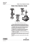
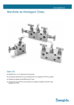
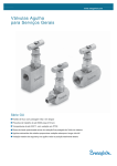
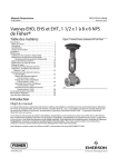
1
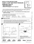
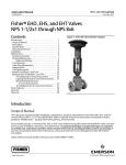
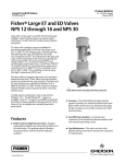
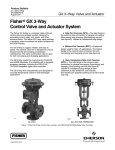
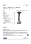
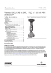
Product Bulletin EH and EHA Valves 51.2:EH April 2015 D100042X012 Fisherr EH and EHA Control Valves EH (globe) J EHS (NPS 1-1/2x1 through 8x6), J EHD (NPS 2 through 20), and J EHT (NPS 2 through 16x12) EHA (angle) J EHAS (NPS 3 through 6), J EHAD (NPS 3 through 8), and J EHAT (NPS 3 through 8) EH Series Valves These valves are specially designed for high-pressure applications. Fisher EH valve configurations incorporate proven techniques in flow-stream contouring for higher capacities and in valve trim design for reliability in severe applications. X1083 The temperature limits of EHT valves can be extended above 232_C (450_F) by using PEEK (PolyEtherEtherKetone) anti-extrusion rings in combination with a spring-loaded PTFE seal. The PEEK anti-extrusion rings expand to close off the clearance gap between the plug and the cage where the PTFE seal may extrude at high temperatures and pressures. The temperature limits are extended to 316_C (600_F) for non-oxidizing service and to 260_C (500_F) for oxidizing service. Unless otherwise noted, all NACE references are to NACE MR0175-2002. Contact your Emerson Process Management sales office. for information on NACE MR0175/ISO 15156 or NACE MR0103. Features n Improved Cage Design—Drilled-hole cages, offering excellent strength and additional resistance to destructive vibration, are standard. Special materials of construction are readily available. www.Fisher.com W9768-1 n O-ring Seat Ring Gasket Construction—Use of O-ring construction provides excellent shut-off with minimal seat ring installation torques for temperatures up to 232_C (450_F). O-ring Product Bulletin 51.2:EH April 2015 construction is standard on EHT valves. The flat sheet seat ring gasket construction is available for elevated design temperatures and/or NACE constructions where a suitable O-ring material is not available. n Increased Pressure/Temperature Ratings—Steel EH and EHA valves with buttwelding end connections have Intermediate Standard Ratings. With nondestructive testing, these valves can conform to ASME Intermediate Special Ratings, which allow even higher pressure/temperature applications. See table 7 for specific ratings. EH and EHA Valves D100042X012 valve plug can be used. For low-flow applications where cavitation damage may occur and the minimum required Cv is equal to or greater than 0.05, Cavitrol III with Micro-Flat trim can be used in both EH and EHA valves. Please contact your Emerson Process Management sales office. for more information. For soot-blower applications, a special trim design is available to address noise, vibration, tight shutoff, and thermal cycling which is seen in this application. Please contact your Emerson Process Management sales office. for more information. n Long Trim Life—Hardened materials of construction for the cage, valve plug, cage guiding, and other trim parts are standard for all applications, providing excellent wear resistance. In all applications, rugged cage guiding provides increased valve plug stability. Increased stability results in reduced vibration and other mechanical stresses, which contributes to long trim life. n Piping Economy—The availability of expanded end connections on EH valves may eliminate the need for line swages while accommodating oversized piping arrangements. n Control of Low Flow Rates/Tight Shut-off— Micro-Form or Micro-Flute valve plugs (figure 5 or 6) provide superb rangeability in high-pressure, low-flow applications. A choice of several restricted port diameters helps match valve capacity to required flow, helps provide necessary control with full travel, and helps prevent throttling near the seat. For EHA valves only, and in low-flow applications where cavitation damage may occur, the Micro-Flat style n High-Temperature, Class V Shutoff—Use of the metal C-seal (see figure 17) permits Class V shutoff up to 593_C (1100_F) for up to 4-3/8 inch port in CL2500 rated valves and 5-3/8 inch port in CL1500 rated valves. The metal Bore Seal will permit Class V shutoff up 593_C (1100_F) for 5-3/8 inch ports and larger. n Excellent Stem Sealing—HIGH-SEAL packing systems provide excellent sealing to conserve valuable or hazardous process fluid and to protect against the emission of hazardous or polluting fluids to atmosphere. This system (figure 1) features graphite packing material and heavy-duty live loading. n High Capacity—Careful consideration of aerodynamic and hydrodynamic principles in the design of the flow stream passages results in 30 to 40 percent higher capacity than conventional valves with comparable port sizes and travels. (continued on page 6) Table of Contents EH Series Valves . . . . . . . . . . . . . . . . . . . . . . . . . . . . . . 1 Features . . . . . . . . . . . . . . . . . . . . . . . . . . . . . . . . . . . . . 1 Specifications . . . . . . . . . . . . . . . . . . . . . . . . . . . . . . . . 3 NPS 1-1/2 x 1 through 6 Globe Valves, NPS 3 through 8 Angle Valves . . . . . . . . . . . . . . . . . . . . . . 7 Trims (NPS 1-1/2 x 1 through 6 Globe Valves . . . . . . 8 NPS 8 through 14 Globe Valves . . . . . . . . . . . . . . . . . . 9 Principle of Operation (NPS 8 through 14 Globe Valves) . . . . . . . . . . . . . 10 NPS 20 Globe Valves . . . . . . . . . . . . . . . . . . . . . . . . . 11 2 Custom Design Capability (NPS 20 Globe Valves) . . C-seal Trim Description . . . . . . . . . . . . . . . . . . . . . . . Bore Seal Description . . . . . . . . . . . . . . . . . . . . . . . . . Fisher TSO (Tight Shutoff) Trim Capabilities . . . . . . Trim Selection Guidelines . . . . . . . . . . . . . . . . . . . . . Material Selection Guidelines . . . . . . . . . . . . . . . . . . Pressure/Temperature Limits . . . . . . . . . . . . . . . . . . Installation . . . . . . . . . . . . . . . . . . . . . . . . . . . . . . . . . Dimensions . . . . . . . . . . . . . . . . . . . . . . . . . . . . . . . . . 12 13 14 15 18 19 26 29 30 Product Bulletin EH and EHA Valves 51.2:EH April 2015 D100042X012 Specifications Valve With DST Trim: J 103 bar (1500 psi) for three-stage trim, J 207 bar (3000 psi) for four-stage trim, and J 289 bar (4200 psi) for six-stage trim. Consult Fisher bulletin 80.2:021, Fisher Dirty Service Anti-Cavitation Trim (DST), D102310X012 for more information Valve With Whisper Trim™ III Cage: J 0.6 ΔP/P1 maximum for Levels A1 and A3, J 0.75 ΔP/P1 maximum for Levels B1 and B3, J 0.85 ΔP/P1 maximum for Levels C1 and C3, J 0.99 ΔP/P1 maximum for Levels D1 and D3 Valve with WhisperFlo™ Trim: J Levels X, Y, and Z: 0.94 ΔP/P1 maximum. If greater than 0.94 ΔP/P1, consult your Emerson Process Management sales office. Available Configurations See table 1 Common Characteristics: EH valves are single-port, high-pressure, globe-style valves with metal seats, cage guiding, and push- down- to- close valve plug action. EHA valves are angle versions of EH valves EHD/EHAD: Uses a balanced valve plug(1) with graphite valve plug piston rings; also, see tables 4 and 5 EHS/EHAS: Uses an unbalanced valve plug. For low-flow applications, smaller valve sizes are available with specialized valve plug designs. See tables 4(1) and 5 EHT/EHAT: Uses a balanced valve plug(1) with a pressure-assisted PTFE valve plug seal ring; also, see tables 4 and 5 NPS 20 Valve Rating J Intermediate Standard Class 2185 (per ASME B16.34) or J other ratings available per customer specifications Valve Sizes J Globe Valves: Tables 4 and 6 J Angle Valves: Table 5 End Connection Styles(2) Buttwelding Ends (BWE): See table 6 for all available ASME B16.25 schedules that are compatible with ASME B16.34 pressure/temperature ratings Flanged Ends: J CL900, J CL1500, or J CL2500 J ring-type joint (RTJ) or J raised-face (RF) flanges according to ASME B16.5. Flanged ends for EHA valves are available in CL900 and 1500 only Socketweld Ends (SWE): See table 6 for those valve sizes available with socketweld end connections according to ASME B16.11 that are compatible with ASME B16.34 Maximum Inlet Pressures and Temperatures(2,3) Consistent with applicable CL900, 1500, or 2500 pressure/temperature ratings (for EH valves) according to ASME B16.34 unless limited by individual temperature limits shown in the Material Temperature Capabilities specification(7) or in figure 20. In addition, both steel EH and EHA valves with BWE connections have increased pressure/ temperature ratings as shown in table 7 Maximum Pressure Drops(3) Valve With Standard Cage: See figures 20, 21, and 22 Valve With Cavitrol™ III Cage: 149 bar (2160 psi) for two-stage cage and 207 bar (3000 psi) for three-stage cage. Consult Fisher Bulletin 80.2:030, Fisher Cavitrol III One-, Two-, and Three-Stage Trims, D100196X012 for more information Construction Materials All Except NPS 20 Valve Body and Bonnet: J WCC steel, J LCC steel, J WC9 chrome-moly steel, J C12A chrome-moly alloy, or J CF8M (316 SST or 316H SST for service above 538_C [1000_F]) Trim: Trim materials are listed in table 10 and 11. Special materials for trim and valve body are available. Please consult your Emerson Process Management sales office. Other Parts: See tables 12 and 13 Yoke Temperature Limit (NPS 8 to 20 Valves): Standard bonnet with cast iron yoke is limited to 537_C (1000_F) NPS 20 Valve Valve Body and Bonnet: SA 217 Grade WC9 steel Cage: Cast M152 SST Valve Plug: CF8M (316 stainless steel) with alloy 6 seat and guide Seat Ring: CF8M with CoCr-A (alloy 6) seat or N06600 with CoCr-A seat Seat Ring Bolting: N07718 Valve Stem: J SA 286 Grade 660 Condition 2 stainless steel or J other materials upon request Piston Rings: Graphite Cage & Seat Ring Gaskets: Silver-plated N04400 Body/Bonnet Bolting: J B7/2H, J B16/Gr-7 Packing Rings: Carbon/graphite composition, graphite, and zinc Packing Box Bushing: Graphite Packing Box Flange, Studs, and Nuts: S31600 (316 stainless steel) (other materials are available on request) Packing Springs: J G61500 (6150 steel), J S17700 (17-7 stainless steel), or J N07718 - continued - 3 Product Bulletin EH and EHA Valves 51.2:EH April 2015 D100042X012 Specifications (continued) Shutoff Classifications Flow Coefficients See Fisher Catalog 12 section 1 See table 9 For NPS 20 valves, one-half of Class IV leakage (0.005% of valve capacity at full travel) per ANSI/FCI 70-2 and IEC 60534-4 Noise Levels See Fisher Catalog 12, section 3 for noise predictions methods Material Temperature Capabilities(3) NPS 20 Valve Maximum Flow Coefficient EHD/EHAD and EHS/EHAS: Up to 593_C (1100_F) unless limited by selection of standard trim materials (table 10 and 11 and figures 20, 21, and 22), Cavitrol III and Whisper Trim III trim materials (table 10), or other parts (table 12) EHT/EHAT: Up to 316_C (600_F) unless limited by selection of standard trim materials (tables 10 and 11 and figures 20, 21, and 22), Cavitrol III and Whisper Trim III trim materials (table 10), or other parts (tables 12 and 13) Approximately 92,000 Cg or 2600 Cv for modified equal percentage characteristics Port Diameters See tables 17 and 18 for NPS 1 through 6 for NPS 1 through 6 NPS 8 and 10x8 Valves CL1500: 178 mm (7 inch) port diameter CL2500: 137 mm (5.375 inch) port diameter NPS 12, 14, and 14x12 Valves CL1500: 254 mm (10 inch) port diameter CL2500: 178 mm (7 inch) port diameter NPS 16x12 Valves CL1500: 254 mm (10 inch) port diameter CL2500: 254 mm (10 inch) port diameter NPS 20 Valves: 355.6 mm (14 inches) Flow Characteristic Standard Cage: J Equal percentage, J modified equal percentage(4), or J linear Micro-Form Valve Plug (for EHS and EHAS only): J Equal percentage or J modified equal percentage(4). Micro-Flute Valve Plug (for EHS and EHAS only): J Equal percentage or J modified equal percentage(4) Micro-Flat Valve Plug (EHAS only): J Linear Cavitrol III, Whisper Trim III, or WhisperFlo: J Linear Special cages: Special characterized flow characteristic cages are available. Please consult your local Emerson Process Management sales office. Valve Plug Travel and Stem Diameters(9) See tables 14, 17, and 18 5 Inch H(10) Boss Diameter: 31.8 mm (1.25 inches) stem diameter 7 Inch Boss Diameter: 50.8 mm (2 inches) stem diameter NPS 20 Valves: Valve Plug Travel: 85.7 mm (9.125 inches) Valve Stem Diameter: 50.4 mm (2 inches) Flow Direction Standard Cage J EHD: Normal flow down(8) J EHS: Normal flow up(5) J EHT: Normal flow down(8) J EHAD: Normal flow down J EHAS: Normal flow up J EHAT: Normal flow down Bonnet Style J Standard bonnet (figures 3 and 4) for all valve sizes, standard bonnet with cast iron yoke is limited to 537_C (1000_F) J Optional Style 1 extension bonnet for NPS 1 and 2 globe valves, see figure 24 Cavitrol III Cage: Flow down Whisper Trim III cage: Flow up Packing Arrangements J Single, J double, and J leakoff standard packing arrangements, or optional J HIGH-SEAL packing systems; see Fisher bulletin 59.1:061, ENVIRO-SEAL™ and HIGH-SEAL Packing Systems for Sliding-Stem Valves, D101633X012 WhisperFlo Trim: Flow up For NPS 20 Valves: J Flow up through seat ring and out through cage openings (for standard and Whisper cages) - continued - 4 Product Bulletin EH and EHA Valves 51.2:EH April 2015 D100042X012 Specifications (continued) Yoke Boss Diameters for Actuator Mounting See table 19 NPS 8 and 10 CL2500 Valves: 127 mm (5 inch H(10)) yoke boss diameter All Other Sizes and Ratings: J 127 mm (5 inch H(10)) or J 178 mm (7 inch) yoke boss diameter NPS 20 Valve: 178 mm (7 inches) Approximate Weight See tables 20 and 21 Options J Flat sheet seat ring gasket constructions(6), J driver for removing and installing of seat ring retainer, J Class V shutoff for EHT above 232_C (450_F) to 316_C (600_F) by using PEEK anti-extrusion rings, J Class V shutoff for EHD up to 593_C (1100_F) using C-seal trim or Bore Seal (refer to table 9, J lubricator/isolating valve for packing lubrication, and J liner with integral seat ring (EHA Series valves only) Options for NPS 20 Valve Tool Kit: Includes tools useful during maintenance [3 sets of lifting eyes, 2 hoist rings, flushing plate with either J two O-rings for use when flushing fluid is 149°C (300°F) or less or J two silver-plated N04400 gaskets for use when flushing fluid is over 149°C (300°F), valve stem lifting nut, lapping fixture and handle, and tamping tools] Special Cage Characterization: Standard, Cavitrol, or Whisper Trim cage openings as necessary to provide the required installed flow characteristic 1. In flow up applications only, NPS 6 to 14 EHD and EHT and NPS 8 EHAD and EHAT valves are available with a diverter cone valve plug construction to provide increased stability for higher pressure drops. See figures 7 and 12. Diverter cone valve plug construction is also used for NPS 6 EHD and EHT and NPS 8 EHAD and EHAT applications requiring Whisper Trim III Level A, B, or C cages. Again, for flow up applications only. 2. EN (or other) ratings and end connections can usually be supplied; please consult your Emerson Process Management sales office.. 3. The pressure or temperature limits in this bulletin and any applicable standard limitations should not be exceeded. 4. Modified equal percentage characteristic is equal-percentage for the first 90% of travel, then quick-opening for additional capacity. 5. EHS may be used for flow down in special cases. Please consult your Emerson Process Management sales office. NPS 1 and 2 valves with Micro-Form plugs can only be used for flow up applications 6. O-ring seat ring gasket construction is preferred where temperature allows and is standard for EHT valves. See table 12. 7. For temperatures above 204_C (400_F), the following CF8M (316 SST) valves must be derated: NPS 8 and 10 ASME Special CL1500 or 2500 valves; NPS 12 and 14 ASME Standard or Special CL2500 valves. For more information, contact your Emerson Process Management sales office.. 8. NPS 8 to 14 flow up for boiler feedwater service with pressure drop greater than 69 bar (1000 psi) when a diverter plug is used. 9. Valves using an equal percentage cage may be traveled an additional 13 mm (0.5 inch) if desired to obtain additional capacity; flow characteristic becomes modified equal percentage. 10. H indicates heavy actuator-to-body bolting. Figure 1. Typical HIGH-SEAL Packing System Figure 2. Seat Ring Gasket Constructions SEAT RING RETAINER PACKING BOX STUD SEAT RING SEAT RING RETAINER O-RING VALVE BODY SEAT RING SPRING PACKING FOLLOWER W4434-2* VALVE BODY O-RING GASKET CONSTRUCTION, STANDARD CONSTRUCTION FOR EHT, CAVITROL TRIMS, AND SOUR SERVICE 1 W5801-3 LAMINATED GRAPHITE GASKET LAMINATED GRAPHITE GASKET CONSTRUCTION NOTES: Preferred for all other body constructions where temperature allows. 1 5 Product Bulletin EH and EHA Valves 51.2:EH April 2015 D100042X012 Table 1. Availability Chart Valve Size, NPS(1) CL1500 CL1500 Intermediate CL2500 CL2500 Intermediate 1-1/2 x 1 --- --- EHS EHS 2x1 --- --- EHS --- 2 --- --- --- EHD, EHS, EHT 3x2 --- --- EHD, EHS, EHT EHD, EHS, EHT EHD, EHS, EHT EHAD, EHAS, EHAT 3 --- EHAD, EHAS, EHAT EHD, EHS, EHT EHAD, EHAS, EHAT 4x3 --- --- EHD, EHS, EHT --EHD, EHS, EHT EHAD, EHAS, EHAT 4 --- EHAD, EHAS, EHAT EHD, EHS, EHT EHAD, EHAS, EHAT 6x4 --- --- EHD, EHS, EHT --- EHAD, EHAS, EHAT EHD, EHS, EHT EHAD, EHAS, EHAT EHD, EHS, EHT EHAD, EHAS, EHAT 6 --- 8x6 --- --- EHD, EHS, EHT --- 8 EHD, EHT EHD, EHT EHAD, EHAT EHD, EHT EHAD, EHAT EHD, EHT 10 x 8 EHD, EHT EHD, EHT EHD, EHT EHD, EHT 12 EHD, EHT EHD, EHT EHD, EHT EHD, EHT 14 --- --- EHD, EHT --- 14 x 12 EHD, EHT EHD, EHT EHD, EHT EHD, EHT 16 x 12 --- --- EHD, EHT --- 20 EHD --- EHD(2) --- 1. Two numbers indicate end connection by nominal valve size. For example, 3 x 2 indicates 3 inch end connection with NPS 2 valve size. 2. CL2185 Table 2. Liquid Flow Coefficients, Cv, at Maximum Travel with Equal Percentage Cage (Modified Equal Percentage Characteristic) (NPS 8 through 14 Valves)(1) VALVE DESIGN EHD, EHT VALVE SIZE, NPS PRESSURE RATING 8 and 10x8 12 and 14x12 CL1500 912 1830 CL2500 584 1010 1. See Fisher Catalog 12 for additional sizing data. Features (continued) n Long Thermal-Cycle Life—The seat ring design minimizes operational stresses, thereby reducing chances of distortion and resultant leakage caused by temperature cycling. The hung cage design allows thermal expansion of the cage without affecting the seat ring gasket loading. n Operational Economy—Balanced trim constructions reduce forces acting on the valve plug, thus reducing actuator thrust requirements and permitting the use of smaller actuators. This, combined with capacities higher than comparably priced globe valves, makes the NPS 8 through 14 6 (including 14x12 and 16x12) EH Series valves very economical for high-pressure, high-flow service. Actuator selection for NPS 20 valves can be made from electromechanical or electrohydraulic styles that use readily available power sources. n Reliability—All aspects of the control valve (material selection, trim components, packing, and control accuracy) are designed, built, and tested to assure performance and reliability. Extensive metallurgical evaluation results in state-of-the-art cage, valve plug, and stem materials that help ensure trim life and dependable performance. n Control Accuracy—The NPS 20 cage and valve plug deliver accurate control of high pressure and high capacity flow. Each cage has milled openings and is flow tested for the required flow characteristic. With precise, accurate cage openings, accurate installed characteristics result; valves in parallel have the same flow at the same plug position. The cone-shaped plug reduces fluid turbulence, helps ensure plug stability, and aids positioning accuracy. n Easy Maintenance—The bonnet lifts off to allow trim access. The separate seat ring and cage allow parts removal and maintenance. The globe configuration reduces the uneven trim wear and resultant EH and EHA Valves D100042X012 maintenance downtime normally associated with slant configurations. Installation with the stem vertical above the bonnet also makes trim removal and installation easy. Product Bulletin 51.2:EH April 2015 characterization and efficient flow passages provide close control for low flow, high pressure drop conditions as well as high flow, low pressure drop conditions. A choice of actuator styles allows wide selection of power and control capabilities. Figure 3. NPS 3 Fisher EH Valve with 657 Actuator NPS 1-1/2 x 1 through 6 Globe Valves NPS 3 through 8 Angle Valves EH Series valves (figure 3) offer higher capacities, rugged cage guiding, hardened trim materials, and are available with special trims for noise attenuation and cavitation abatement. An EH valve package can be created for specific service conditions from a variety of special features, including oversized ends, intermediate ratings, special trim materials, and special trim configurations. W3387 Figure 4. Fisher EHD Valve Body Assembly Because of flow capacity and severe service capabilities, both EH and EHA valves are used for many high-pressure applications in process industries such as power generation, hydrocarbon production, chemical processing, and refining. The EHD (figure 4) uses a balanced valve plug and is well suited for general applications where extremely tight shutoff is not required. The EHS (figures 5 and 6) has an unbalanced valve plug and provides up to Class V shutoff. The EHT has a balanced valve plug and offers up to Class V shutoff with process temperatures below 232_C (450_F). EHA valves--EHAD, EHAT, and EHAS--are angle versions of the EH valve. W3379-1 n Control Flexibility—Special cage characterization (standard, Whisper Trim, or Cavitrol trim) can be supplied to satisfy almost any combination of flow and noise or cavitation abatement. Cage EH valves are available in CL2500 ratings. EHA valves are available in CL2500. Because these valves feature a thicker body wall, both EH and EHA valves are available with intermediate ratings. See the Features section in this bulletin. EHA valves provide many of the same features available with EH valves. One important feature is the availability of special trims for aerodynamic noise attenuation, for cavitating liquid service, and for sour service. 7 Product Bulletin EH and EHA Valves 51.2:EH April 2015 D100042X012 Trims (NPS 1-1/2 x 1 through 6 Globe Valves) Figure 5. Fisher EHS Trim with Micro-Form Valve Plug Figure 6. Fisher EHS Trim with Micro-Flute Valve Plug FLOW W5042-1 FLOW W5043-1 Figure 7. Diverter Cone Plug Used in NPS 6 Fisher EHD and EHT Valves (Flow Up Only) FLOW W5041-1 Diverter cone valve plug used for flowing ΔP> 207 bar (3000 psi) or for Whisper Trim III Level A, B, or C cages. 8 Product Bulletin EH and EHA Valves 51.2:EH April 2015 D100042X012 Figure 8. Fisher EHD Valve Assembly (NPS 8 through 14 Globe Valves) VALVE STEM GASKETS CAGE PISTON RINGS PIN VALVE PLUG FLOW SEAT RING CAP SCREW GASKET W4425-1 SEAT RING Figure 9. NPS 8 Fisher EH Valve with Welded Pipe Expanders and 585C Actuator NPS 8 through 14 Globe Valves EH Series control valves (figure 9) are large, high-pressure globe valves that incorporate proven techniques in flow-stream contouring and in seat ring and valve plug design. These features, along with rugged cage guiding and hardened trim materials, make the EH Series valves reliable high-capacity valves. These valves are used for many high-pressure applications in the power, process, oil production, chemical, refining, and other industries. The EHD valve (figure 8) is well-suited to general applications where extremely tight shutoff is not required, and the EHT valve (figure 10) offers up to Class V shutoff for applications with relatively low process temperatures. W9768-1 9 Product Bulletin EH and EHA Valves 51.2:EH April 2015 D100042X012 Principle of Operation (NPS 8 through 14 Globe Valves) Figure 12. Diverter Cone Valve Plug Used in Fisher EHD and EHT Valves (NPS 8 through 14 Globe Valves, Flow Up Only) EHD and EHT valves, shown in figures 8 and 10, are balanced valve designs. When the valves are opening or closing, pressure registers on top of the valve plug through the balancing holes in the plug. The force of the pressure on top of the plug balances the force of the pressure on the bottom of the plug to reduce the actuator force required. Figure 10. Fisher EHT Trim (NPS 8 through 14 Globe Valves) RETAINING RINGS BACKUP RING PRESSUREASSISTED SEAL RING DIVERTER CONE W4430-1 DIVERTER CONE VALVE PLUG USED IN BOILER FEEDWATER SERVICE FOR FLOWING ΔP> 1000 PSI (69 BAR) AND IN OTHER APPLICATIONS FOR FLOWING ΔP> 138 BAR (2000 PSI) OR FOR WHISPER TRIM III LEVEL A, B, OR C CAGES Figure 13. Seat Ring Gasket Constructions (NPS 8 through 14 Globe Valves) SEAT RING FLOW VALVE BODY W4426-1 Figure 11. Fisher EHD Trim with Whisper Trim III Level D Cage (NPS 8 through 14 Globe Valves) SPIRAL WOUND GASKET SEAT RING CAP SCREW SPIRAL WOUND GASKET CONSTRUCTION (STANDARD CONSTRUCTION FOR HIGH TEMPERATURE APPLICATIONS) SEAT RING VALVE BODY O-RING SEAT RING CAP SCREW W4429-1 FLOW W4428-1 10 O-RING GASKET CONSTRUCTION (STANDARD CONSTRUCTION FOR SOUR SERVICE AND OPTIONAL FOR OTHER VALVE CONSTRUCTIONS) Product Bulletin EH and EHA Valves 51.2:EH April 2015 D100042X012 Figure 14. Sectional of NPS 20 Fisher EHD Control Valve Assembly CAGE VALVE PLUG AND STEM ASSEMBLY FLOW SEAT RING W4282-2 NPS 20 Globe Valves The NPS 20 EHD control valve (figure 15) is a large, high-pressure, single-port, globe valve designed to closely and dependably control high-pressure, high-temperature media in the power and hydrocarbon industries. For example, NPS 20 EHD control valves are used in sliding pressure systems to control high-pressure steam in fossil-fueled power plants. Advanced, yet successfully field-proven, the NPS 20 EHD control valve usually incorporates special design features to satisfy specific customer requirements. For example, figure 14 illustrates a specially characterized cage. Both Whisper Trim cage holes and large cage windows provide the customer-required flow characteristic. Additionally, the drilled Whisper Trim holes in the cage provide noise abatement. Standard construction details such as the cone-shaped valve plug and stem assembly, separate seat ring, and HIGH-SEAL packing arrangement are also shown in figure 14. 11 Product Bulletin EH and EHA Valves 51.2:EH April 2015 Figure 15. NPS 20 Fisher EHD Valve with Electromechanical Actuator D100042X012 Figure 16. Custom Design Sequence (NPS 20 Globe Valves) BASIC DESIGN •FIELD-PROVEN CUSTOMER SPECIFICATIONS CUSTOM DESIGN TEST AND EVALUATION FINAL DESIGN •SPECIAL CHARACTERIZATION •ACTUATOR/VALVE BODY RESPONSE •FLOW CAPACITY •CHARACTERISTIC •STABILITY •ULTIMATE RELIABILITY A3350 Custom Design Capability (NPS 20 Globe Valves) Sliding pressure systems, as well as other control systems, have specific performance characteristics that require special control valve constructions. These special constructions must perform dependably and provide accurate system operation and plant reliability. As shown in figure 16, the basic NPS 20 EHD valve configuration can be designed to meet customer specifications. Special cage characterization and actuator/valve response characteristics can be designed and then confirmed through exhaustive testing and evaluation. Flow testing of these large valves takes place at the Emerson Innovation Center, Fisher Technology, the largest facility of its kind in the world. W4182-1 12 The final control valve assembly provides reliable, dependable performance. This performance delivers controllability for not only the control valve but also the plant control system, sliding pressure or otherwise. Product Bulletin EH and EHA Valves 51.2:EH April 2015 D100042X012 Figure 17. C-seal Trim STAKE THREAD PISTON RING A RETAINER C-seal METAL PLUG SEAL(1) VALVE PLUG FLOW DOWN RETAINER C-seal METAL PLUG SEAL(1) A6869 C-seal METAL PLUG SEAL FLOW UP 1 VALVE PLUG CAGE VIEW A UPPER SEATING SURFACE NOTES: Reverse the orientation of the C-seal plug seal for proper shutoff when valve is used in a process with different fluid flow direction. 1 C-seal Trim Description With C-seal trim, a balanced valve can achieve high-temperature, Class V shutoff. Because the C-seal plug seal is formed from metal (N07718 nickel alloy) rather than an elastomer, a valve equipped with the C-seal trim can be applied in processes with a fluid temperature of up to 593_C (1100_F). 13 Product Bulletin EH and EHA Valves 51.2:EH April 2015 D100042X012 Figure 18. Bore Seal RETAINER PISTON RING CAGE CAGE SEATING AREA SEATING AREA PLUG FLOW DOWN BORE SEAL BORE SEAL RETAINER PISTON RING CAGE A SEATING AREA PLUG FLOW UP BORE SEAL VIEW A Bore Seal Description is secured to the outside diameter of the valve plug. When the valve plug comes into contact with the seat ring to close the valve, the Bore Seal is compressed against the cage wall, thereby blocking a secondary leakage path that exists between the plug and cage wall. When the valve plug is not in contact with the seat ring (i.e. valve open), the Bore Seal is not engaged and the piston rings that are also secured to the outside diameter of the plug assume the role of blocking this secondary leakage path. The Bore Seal (figure 18) is available for the EHD only and employs a variation of the proven Cseal trim with enhancements for use with the larger port EH hung cage. The Bore Seal is required for Class V shutoff applications where the service temperature exceeds 316_C (600_F). See table 3 for availability and temperature limits. The Bore Seal employs a metal Cshaped seal ring that Table 3. Bore Seal Availability and Temperature Limits (EHD only) VALVE (PRESSURE CLASS) EHD (CL1500 - CL2500) VALVE SIZE, NPS 8, 10, 12, and 14 VALVE BODY MATERIAL 75 WCC/WC9 29 to 427 20 to 800 WCC 315 to 427 600 to 800 WC9 315 to 593 600 to 1100 WCC/WC9 29 to 427 20 to 800 95 96 1. See tables 11 and 13 for materials. 14 TEMPERATURE LIMIT TRIM DESIGNATION(1) _C _F ANSI/FCI/IEC SHUTOFF CLASS V Product Bulletin EH and EHA Valves 51.2:EH April 2015 D100042X012 Fisher TSO (Tight Shutoff) Trim Capabilities Figure 19. Typical Balanced TSO (Tight Shutoff) Trim TSO trim consists of a protected soft seat plus PEEK anti-extrusion rings with a spring-loaded PTFE plug seal. Used only in flow down applications, TSO trim offers unparalleled shutoff integrity, resulting in long plug and seat life. See figure 19 and tables 8 and 9. For additional information contact your Emerson Process Management sales office.. VALVE PLUG SEAL PROTECTED SOFT SEAT W7020-1 Table 4. Available Globe Valve Configurations and Valve Sizes(1) (NPS 1-1/2 x 1 through 6 Globe Valves) AVAILABLE CONFIGURATIONS Valve Design EHS EHT EHD VALVE SIZES (NPS) AND PRESSURE RATING 1-1/2 x 1, 2 x 1 2 3x2 3, 4 x 3 4, 6 x 4 6, 8 x 6 CL2500 CL3273 CL2500 CL2500 CL2500 CL2500 Quick-Opening(2) X X X --- --- --- Standard(3) --- X X X X X Whisper Trim III --- X X X X X Cavitrol III: 2-stage 3-stage X --- --X --X ----- ----- ----- Standard(3) --- --- X X X X Whisper Trim III --- --- X X X X Cavitrol III: 2-stage 3-stage ----- ----- X --- X X X X X X Standard(3) --- --- X X X X Whisper Trim III --- --- X X X X Valve Plug Style Cage Style Micro-Form Standard Standard Standard X—Indicates available construction. 1. Two numbers indicate end connection by nominal valve size. For example, 3 x 2 indicates 3 inch end connection with NPS 2 valve size. 2. Linear cage used on NPS 2 and 3 x 2 valves. 3. Standard cages are equal percentage, modified equal percentage, and linear cages. 15 Product Bulletin EH and EHA Valves 51.2:EH April 2015 D100042X012 Table 5. Available Angle Valve Configurations and Valve Sizes (NPS 1 through 6 Angle Valves) AVAILABLE CONFIGURATIONS VALVE SIZES (NPS) AND PRESSURE RATING Valve Plug Style Cage Style 1-4 6(4) CL2500 CL3230 Micro-Form Quick-Opening(1) X(3) --- Micro-Flute Quick-Opening --- --- Standard(2) X X Whisper Trim III X X Cavitrol III: 2-stage 3-stage ----- ----- Standard(2) X X Whisper Trim III X X Cavitrol III: 2-stage 3-stage X X X X Standard(2) X X Whisper Trim III X X Valve Design EHAS Standard EHAT Standard EHAD Standard X—Indicates available construction. 1. Linear cage used on NPS 2 and 3 valves. 2. Standard cages are equal percentage, modified equal percentage, and linear cages. 3. Not available in NPS 4 and larger. 4. Intermediate CL3230. Contact your Emerson Process Management sales office.. Table 6. Globe Valve Sizes and End Connection Styles(1) (NPS 1-1/2 x 1 through 6 Globe Valves) CL2500(2) VALVE SIZE, NPS SCH 80 SCH 160 SCH XXS 1-1/2 x 1 2x1 X X ----- 2(3) 3x2 3 4x3 4 --X X X X 6x4 6 8x6 X X X BWE SWE RTJ RF X X X X X X X X ----------- X X X X X ----------- --X X X X --X X X X ----X X X --- ------- X X X X X X X—Indicates available construction. 1. EN (or other) ratings and end connections can usually be supplied; consult your Emerson Process Management sales office.. 2. For valve ratings of EH Series valves with BWE connections, refer to separate bulletin. Increased Pressure/Temperature Ratings for EH Series and EW Series Steel Valves (D100075X012 or D100076X012). 3. Intermediate CL3273 only. Table 7. Increased Pressure/Temperature Ratings for Steel Fisher EH Series Globe Valves with Buttwelding End Connections(1) VALVE SIZE, NPS CL1500 CL2500 Intermediate Rating (ASME B16.34) Intermediate Rating (ASME B16.34) 1 --- 3862(2) 1-1/2 x 1 --- 3021 2 --- 3273 3 --- 2932 4 --- 3294 6 --- 2987 8 1866 2943 10x8 1568 2522 12 1650 2940 14 x 12 1650 2754 1. See Fisher bulletin 59.1:026, D100075X012, for additional information. 2. Intermediate rating of 4080 is available with special bolting materials in most valve body materials. Contact your Emerson Process Management sales office.. 16 Product Bulletin EH and EHA Valves 51.2:EH April 2015 D100042X012 Table 8. Port Diameters, Valve Plug Travel, Yoke Boss Diameters for TSO (Tight Shutoff) Trim MAX TRAVEL VALVE DESIGN TRIM EHT NPS 6 CAV III 3-Stage CL2500 EHT NPS 6 Std CL2500 mm PORT DIAMETER YOKE BOSS SIZE Nominal Actual TSO Cv REDUCTION AT 100% TRAVEL(1) Inch mm Inch mm Inch mm Inch 95.3 3.75 90 127 3-9/16 5 111 4.375 106 4.1875 0% 76.2 3 90 127 3-9/16 5 111 4.375 106 4.1875 5% (linear) 5% (equal %) 1. This column lists the percent reduction of published maximum Cv of the trim listed in the TRIM column. Table 9. Shutoff Classifications per ANSI/FCI 70-2 and IEC 60534-4 Valve Design Port Diameter, mm (inch) EHD/EHAD EHD (CL1500) Valve Size, NPS 8 10x8 12 14 x 12 4 6x4 ANSI/FCI Leakage Class 47.6 mm (1.875 inch) and smaller II 58.7 mm (2.3125 inch) to 92.1 mm (3.625 inch) II—Standard III—Optional 111.1 mm (4.375 inch) and larger III—Standard IV—Optional Port Diameter, mm (inch) Cage Style ANSI/FCI Leakage Class 177.8 (7) 254 (10) Eq. %, Mod. Eq. % Linear (std. cage) Linear (Whisper III, A1, B3, C3) V - Standard to 593_C (1100_F) (for port diameters from 177.8 (7 inch) through 254 mm (10 inch) with optional Bore Seal) 73 (2.875) Eq. %, Mod. Eq. %, Linear (std. cage), Linear (Whisper III, A1, B3, C3) Linear (Cav III, 2-stage) EHD (CL2500) 6 8x6 111.1 (4.375) Eq. %, Mod. Eq. %, Linear (std. cage), Linear (Whisper III, A1, B3, C3, D3) V - Standard to 593_C (1100_F) (for port diameters from 73 through 136.5 mm [2.875 through 5.375 inches] with optional C-seal trim) Linear (Cav III, 2- and 3-stage) 8 10x8 136.5 (5.375) 12 14x12 177.8 (7) EHS, EHAS, EHT, EHAT EHS, EHAS, EHT, EHAT Eq. %, Mod. Eq. %, Linear (std. cage), Linear (Whisper III, A1, B3, C3, D3) V - Standard to 593_C (1100_F) (for port diameters from 136.5 through 177.8 mm [5.375 through 7-inches] with optional Bore seal) All Cavitrol III V All Std or w/ Micro-Form or w/ Micro-Flute IV—Standard, V—Optional EHT w/ TSO (Tight Shutoff) See table 8 See table 8 TSO - Optional TSO is not an ASME leakage class. Valves with TSO trim are factory tested to a more stringent Fisher test requirement of no leakage at time of shipment. Test medium is water. Specify service ΔP when ordering. Test procedure is ANSI/FCI Class V test procedure B. EHT w/ PEEK(1) Anti-Extrusion Rings 25.4 (1) to 254 (10) All V to 316_C (600_F) 1. PEEK (PolyEtherEtherKetone) 17 Product Bulletin 51.2:EH April 2015 Trim Selection Guidelines for NPS 1-1/2 x 1 through 6 Globe Valves Please refer to the following descriptions as a guideline for the selection of appropriate trims: n Trim 49--Trim 49 is the standard trim for C12A valve body materials and should only be used with C12A valve body materials. C12A should only be used when the pressure and temperature capabilities for WC9 valve body materials are not acceptable. n Trim 50--Trim 50 is the standard trim for carbon steel and alloy steel body materials and is recommended for general and severe service applications up to 427_C (800_F). Typical applications for Trim 50 include services in water, boiler feedwater, non-sour hydrocarbons, and steam. The S41600 (416 stainless steel) 18 EH and EHA Valves D100042X012 heat-treated plug and seat ring have a hardness similar to CoCr-A (Alloy 6). n Trim 53--Trim 53 should be used in all high temperature applications between 427_C (800_F) and 566_C (1050_F) unless chlorides are present. The presence of chlorides could lead to stress corrosion cracking of the CA28MWV (422 stainless steel) cage. n Trim 54--Trim 54 is the standard trim for stainless steel body materials. It should be used where hard-faced trim is specified. n Trim 56--Trim 56 should be used for sour service. n Trim 57--Trim 57 shall be used for boiler feedwater service when limits exceed those specified for Trim 50. Care should be taken when specifying this trim in small sizes for applications where chlorides are present due to stress corrosion cracking problems with S44004 (440C stainless steel). Product Bulletin EH and EHA Valves 51.2:EH April 2015 D100042X012 Figure 20. Pressure/Temperature Limits for CL2500 Valves (NPS 1-1/2 x 1 through 6 Globe) WCC STEEL VALVES LCC STEEL VALVES THE LCC LOWER LIMIT CAN BE EXTENDED TO -46_C (-50_F) WITH IMPACT TESTING CF8M (316 OR 316H ABOVE 538°C [1000°F]) STAINLESS STEEL VALVES TYPICAL FOR ALL GRAPHS CL2500 CL1500 CL900 B1960-1* WC9 CHROME-MOLY STEEL VALVES C12A VALVES Note: Do not exceed the maximum pressure and temperature for the pressure rating of the body material and valve size used. Refer to tables 4 and 5 for pressure/temperature limits of the trim used. Intermediate pressure/temperature ratings are found in separate bulletin, Increased pressure/temperature ratings for EH AND EW series steel valves. Material Selection Guidelines Please use these numbered steps as a guideline for the selection of materials: 1. Determine the pressure/temperature rating of the valve size and material required. Inlet pressure and temperature must always be limited by the applicable ASME pressure/temperature rating. 2. Select the desired valve style from the Available Configurations specification and from the shutoff classifications listed in table 9. 3. Select desired materials from tables 10, 11, 12, and 13 and figures 20, 21, and 22. The temperature capabilities determined from figures 20, 21, and 22 may be further limited by the temperature capabilities of materials selected from tables 10, 11, 12, and 13. Refer to figures 20, 21, and 22 to determine pressure drop limits of the body-trim combinations selected. Inlet pressure and temperature must always be limited by the applicable ASME pressure/ temperature rating. Contact your Emerson Process Management sales office. for special materials for temperatures exceeding the following maximum limits: EHD valve [593_C (1100_F)] and the EHT valve [232_C (450_F)]. 19 Product Bulletin EH and EHA Valves 51.2:EH April 2015 D100042X012 Table 10. Trim Material Combinations (NPS 1-1/2 x 1 through 6 Globe Valves) DESIGNATION VALVE PLUG CAGE SEAT RING SEAT RING RETAINER VALVE BODY MATERIAL(6) OPERATING TEMPERATURE RANGE SOUR SERVICE (NACE) Degrees Celsius Degrees Fahrenheit WCC, WC9 -29 to 427 -20 to 800 No WITH STANDARD CAGE S41600 (416 SST) heat-treated(1) 50 S44004 (440C SST) heat-treated for Micro-Flute valve plugs S17400 (17-4PH SST) H1075 heattreated S17400 S41600 H1150D heat-treated heat-treated chrome coat 53(2, 4) S31600 (316 SST) with CoCr-A (Alloy 6) seat and guide S42200 (422 SST) nitrided Alloy 6 N07718 heat-treated chrome coat WC9 427 to 566 800 to 1050 No 54 S31600 with CoCr-A seat and guide CF8M (316 SST) chrome coat Alloy 6 N07718 heat-treated chrome coat CF8M -73 to 593 -100 to 1100 Yes S31600 with CoCr-A seat and guide CF8M ENC -29 to 149 -20 to 300 Alloy 6 S17400 H1150D heat-treated chrome coat WCC, WC9 56(3) CF8M -40 to 149 -40 to 300 57(3) S44004 heat-treated S17400 H1075 heat-treated S44004 heat-treated S17400 H1150D heat-treated chrome coat WCC, WC9 0 to 232 32 to 450 No 49(4, 5) F22 with CoCr-A seat and guide F22 nitrided Alloy 6 N07718 heat-treated chrome coat C12A -29 to 593 -20 to 1100 No Yes WITH CAVITROL III TRIM CAGE 58(3) S44004 heat-treated CB7CU-1 H1075 heat-treated S44004 S17400 H1150D heat-treated chrome coat WCC, WC9 0 to 232 32 to 450 No 59(3) S31600 with CoCr-A seat and guide CB7CU-1 H1150D heat-treated Alloy 6 S17400 H1150D heat-treated chrome coat WCC, WC9 -29 to 232 -20 to 450 Yes WCC, WC9 -29 to 427 -20 to 800 No WCC -29 to 427 -20 to 800 WC9 -29 to 566 -20 to 1050 WITH WHISPER TRIM III CAGE S41600 heat-treated 60 S17400 H900 SST heat-treated for NPS 6 EH only CB7CU-1 H1075 heat-treated S17400 H1150D heat-treated chrome coat Alloy 6 N07718 heat-treated chrome coat Alloy 6 S17400 H1150D heat-treated chrome coat WCC, WC9 -29 to 232 -20 to 450 Yes Alloy 6 N07718 heat-treated chrome coat C12A -29 to 593 -20 to 1100 No S42200 nitrided 61(4) S31600 with CoCr-A seat and guide F22 nitrided for NPS 6 EH only 62(3) S31600 with CoCr-A seat and guide CB7CU-1 H1150D heat-treated F91 with CoCr-A seat and guide S42200 nitrided F22 with CoCr-A seat and guide for NPS 6 EH only F22 nitrided for NPS 6 EH only 63(4, 5) S41600 heat-treated No 1. S17400 H900 stainless steel heat-treated is used when a diverter cone valve plug is specified for port diameters equal to and larger than 4.375 inches. 2. This trim designation not available with the O-ring seat ring gasket construction due to temperature limitations. 3. This trim designation uses the O-ring seat ring gasket construction. See table 12 for O-ring temperature limits. For temperatures greater than 232_C (450_F), flat sheet seat ring gasket with HTS1 seal ring option (up to 316_C (600_F) is available. Consult your Emerson Process Management sales office.. 4. This trim is for use in EHD and EHS constructions only. 5. Trims 49 and 63 use S41000 stem instead of the standard S31600 material. S41000 is limited to 538_C (1000_F). For temperatures greater than 538_C (1000_F), S42200 stem is used. S20910 stem material should not be used with this trim. 6. If using valve body/trim combinations other than those listed, consult your Emerson Process Management sales office.. 20 Product Bulletin EH and EHA Valves 51.2:EH April 2015 D100042X012 Table 11. Trim Material Combinations (NPS 8 through 14 Fisher EHD and EHT) TRIM DESIGNATION VALVE PLUG VALVE PLUG STEM CAGE SEAT RING SEAT RING CAP SCREWS VALVE BODY MATERIAL(5) OPERATING TEMPERATURE RANGE _C _F EHD and EHT Valve with Standard Cage 75 S42000 (420 SST) S20910 CA6NM S17400 H1075 heat-treated S17400 WCC, WC9 -29 to 427 -20 to 800 77 S31600 with CoCr-A (alloy 6) seat and guide S20910 S31600 chrome coat S31600 with CoCr-A seat S66286 (660 SST) CF8M -198 to 593 -325 to 1100 79 S31600 with CoCr-A seat and guide S20910 CA6NM chrome coat N06600 with CoCr-A seat N07718 WCC -29 to 427 -20 to 800 WC9 -29 to 566 -20 to 1050 82(1) S31600 with CoCr-A seat and guide S20910 S31600 ENC 95(3) F22 with CoCr-A seat and guide S41000 heat treated(2) WC9/ nitrided F22 with CoCr-A seat N07718 96 S17400 with CoCr-A seat and guide S17400 H1150D CB7CU-1 H1075 S17400 with CoCr-A seat S17400 97 S17400 with CoCr-A seat and guide S17400 H1150D dbl EHD and EHT Valve with Standard Cage for Sour Service N06600 with CoCr-A seat N07718 WCC, WC9 -29 to 204 -20 to 400 CF8M -198 to 343 -325 to 650 WCC 315 to 427 600 to 800 WC9 315 to 593 600 to 1100 WCC, WC9 -29 to 427 -20 to 800 WCC -29 to 343 -20 to 650 All Valves with Whisper Trim III Cages All Valves with Whisper Trim III Cages for Sour Service(4) S17400 H1150D ENC S17400 with CoCr-A seat S17400 1. Limit to 149_C (300_F) when using N04400 gasket material. 2. S41000 is limited to 538_C (1000_F). For temperatures greater than 538_C (1000_F), an S42200 stem is used. 3. This trim is for use in EHD constructions only. 4. Trim 97 complies with NACE MR0175/2002 and is not NACE MR0175/ISO15156 or NACE MR0103 compliant. 5. If using valve body/trim combinations other than those listed, consult your Emerson Process Management sales office.. 21 Product Bulletin EH and EHA Valves 51.2:EH April 2015 D100042X012 Table 12. Construction Materials and Temperature Capabilities for Parts Other than Body and Trim (NPS 1-1/2 x 1 through 6 Globe Valves) TEMPERATURE CAPABILITIES PART MATERIAL Valve plug stem S31600 (316 stainless steel) S31600/chromium coating S20910 (1) S20910/chromium coating Graphite (FMS 17F27) EHD/EHAD piston ring Graphite (FMS 17F39) EHT/EHAT seal ring EHT/EHAT seal ring backup ring Backup ring Springloaded EHT valve plug seal Retaining ring Seal ring Anti-extrusion ring Cage gasket Seat ring gasket N10276 with glass and moly-filled PTFE Same as base material of valve plug S41600 (416 SST) S30200 (302 SST) N07750(1) R30003 (with glass and moly-filled PTFE) PEEK (PolyEtherEtherKetone) S31600/Graphite(1) O-ring seat ring gasket(1) Flat sheet seat ring gasket Nitrile(5) Ethylene-propylene(6) Fluorocarbon (not for water or steam service)(5) Studs Nuts Steel SA193-B7 (all body materials) Steel SA194-2H (all body materials) Studs Nuts Studs Nuts Studs Nuts Studs Nuts Studs Nuts Steel SA193-B7 (WC9 body mat'l) Steel SA194-7 (WC9 body mat'l) Steel SA193-B16 (WC9 and C12A body mat'ls) Steel SA194-7 (WC9 and C12A body mat'ls) 304 stainless steel SA320-B8 (CF8M [316, 316H body mat'ls]) 304 stainless steel SA194-8 (CF8M [316, 316H body mat'ls]) 316 SST SA193-B8M(3) (CF8M [316, 316H body mat'l]) 316 SST SA194-8M (CF8M [316, 316H body mat'l]) 316 SST SA193-B8M chrome coat(4) (CF8M [316, 316H body mat'ls]) 316 SST SA194-8M (CF8M [316, 316H body mat'ls]) SST SA453 GR660 with Belleville washers (CF8M[316, 316H, body mat'ls] Steel SA194-7 (CF8M [316, 316H body mat'ls] SST SA453 GR660 rupture tested with Belleville washers (CF8M[316, 316H, body mat'ls] Steel SA194-7 (CF8M [316, 316H body mat'ls] SST SA453 GR660 for sour service(1) with Belleville washers (CF8M[316, 316H, body mat'ls] Steel SA194-7M(1) (CF8M [316, 316H body mat'ls] SST SA453 GR660 rupture tested for sour service(1) with Belleville washers (CF8M[316, 316H, body mat'ls] Steel SA194-7M(1) (CF8M [316, 316H body mat'ls] N07718 SST (SB037) Steel SA194-7 Steel SA193-B7M for sour service(1) (CF8M [316 body mat'l]) Steel SA194-2HM for sour service(1) (CF8M [316 body mat'l]) PTFE V-ring Graphite ribbon/filament (oxidizing service to 700_F) Graphite ribbon (high-temperature oxidizing service) HIGH-SEAL packing system (see Fisher Bulletin 59.1:061, ENVIRO-SEAL and HIGH-SEAL Packing Systems for Sliding-Stem Valves (D101633X012), for further information) Body-tobonnet bolting(2) Studs Nuts Studs Nuts Studs Nuts Studs Nuts Studs Nuts Studs Nuts Packing S31600/Graphite(1) -continued- 22 Degrees Celsius -198 to 427 427 to 593 -198 to 593 427 to 593 -46 to 427 (to 482 for nonoxidizing service) -46 to 537 (to 593 for nonoxidizing service) -73 to 232 See table 10 -29 to 427 Degrees Fahrenheit -325 to 800 800 to 1100 -325 to 1100 800 to 1100 -50 to 800 (to 900 for nonoxidizing service) -50 to 1000 (to 1100 for nonoxidizing service) -100 to 450 See table 10 -20 to 800 -254 to 593 -425 to 1100 -73 to 232(7) -100 to 450(7) -73 to 316 -100 to 600 -254 to 427 (to 593 for nonoxidizing service) -29 to 107(8) -40 to 232 -23 to 204 -254 to 427 (to 593 for nonoxidizing service) -29 to 427 (WCC, WC9) -46 to 343 (LCC) -48 to 232 (CF8M [316 and 316H]) -425 to 800 (to 1100 for nonoxidizing service) -20 to 225(8) -40 to 450 -10 to 400 -425 to 800 (to 1100 for nonoxidizing service) -20 to 800 (WCC, WC9) -50 to 650 (LCC) -55 to 450 (CF8M [316 and 316H]) -29 to 454 -20 to 850 -29 to 510 -20 to 950 -198 to 66 -325 to 150 -198 to 66 -325 to 150 -198 to 66 -325 to 150 -29 to 427 -20 to 800 427 to 537 801 to 1000 -29 to 427 -20 to 800 427 to 537 801 to 1000 -29 to 566 (WC9) -29 to 593 (C12A) -20 to 1050 (WC9) -20 to 1100 (C12A) -46 to 232 -50 to 450 -40 to 232 -254 to 537 371 to 593 -40 to 450 -425 to 1000 700 to 1100 See bulletin 59.1:061 See bulletin 59.1:061 Product Bulletin EH and EHA Valves 51.2:EH April 2015 D100042X012 Table 12. Construction Materials and Temperature Capabilities for Parts Other than Body and Trim (NPS 1-1/2 x 1 through 6 Globe Valves) (continued) PART TEMPERATURE CAPABILITIES MATERIAL Packing follower, spring, or lantern ring Packing box ring Packing flange, studs, or nuts Degrees Celsius Degrees Fahrenheit S31600 -254 to 593 -425 to 1100 S31600 Steel S31600 -254 to 593 -29 to 427 -29 to 593 -425 to 1100 -20 to 800 -20 to 1100 1. Complies with NACE MR0175-2002, NACE MR0175-2003, NACE MR0103, and NACE MR0175/ISO 15156. 2. Valve body materials with which these bolting materials may be used are shown in parentheses. 3. Class 1 (annealed). 4. Class 2 (strain hardened). 5. For use with all O-ring seat ring constructions without Cavitrol III trim. 6. For use with all O-ring seat ring constructions with Cavitrol III trim. 7. If used with PEEK anti-extrusion rings, PTFE/carbon seal ring may be used up to 316_C (600_F) for non-oxidizing service or up to 260_C (500_F) for oxidizing service. 8. Temperature range per DS52 Group 2. Table 13. Construction Materials and Temperature Capabilities for Parts Other than Body and Trim (NPS 8 through 14 Fisher EHD and EHT) PART MATERIAL Cage gasket Standard gasket construction Metal seat ring gasket O-ring seat ring gasket Cage gasket Sour service gasket construction TEMPERATURE CAPABILITIES _C _F Silver-plated N04400 -254 to 593 -425 to 1100 S31600/Graphite(1) -254 to 427 (to 593 for nonoxidizing service) -425 to 800 (to 1100 for nonoxidizing service) Graphite filled spiral wound N06600 -254 to 593 -425 to 1100 Nitrile -29 to 107 -20 to 225 Ethylene-propylene -40 to 232 -40 to 450 Fluorocarbon -23 to 204 -10 to 400 Tin-plated N04400 -29 to 149 -20 to 300 S31600/Graphite(1) -254 to 427 (to 593 for nonoxidizing service) -425 to 800 (to 1100 for nonoxidizing service) Nitrile -29 to 107 -20 to 225 Fluorocarbon -23 to 149 -10 to 300 Graphite (FMS 17F27) -46 to 427 (to 482 for nonoxidizing service -50 to 800 (to 900 for nonoxidizing service) Graphite (FMS 17F39) -46 to 537 (to 593 for nonoxidizing service) -50 to 1000 (to 1100 for nonoxidizing service) EHD Bore Seal N07718 -198 to 593 -325 to 1100 EHT seal ring PTFE with N10276 Spring -73 to 232 -100 to 450 EHT seal ring retaining ring S30200 (302 stainless steel) -254 to 593 -425 to 1100 O-ring seat ring gasket EHD piston ring Spring-loaded EHT valve plug seal Backup ring S41600 (416 SST) -29 to 427 -20 to 800 Retaining ring S30200 (302 SST) -254 to 593 -425 to 1100 Seal ring R30003 (with glass and moly-filled PTFE) -73 to 232(3) -100 to 450(3) Anti-extrusion rings PEEK (PolyEtherEtherKetone) -73 to 316 -100 to 600 PTFE V-ring -46 to 232 -50 to 450 PTFE/composition -73 to 232 -100 to 450 Graphite ribbon filament -18 to 371 (to 537 for nonoxidizing service) 0 to 700 (to 1000 for nonoxidizing service) Graphite Ribbon (high temperature oxidizing service) 371 to 649 700 to 1200 Packing HIGH-SEAL (see Bulletin 59.1:061, HIGH-SEAL Packing Systems for Sliding-Stem Valves for information) Packing follower, spring, or lantern ring Packing box ring S31600 (316 stainless steel) -254 to 593 S17400 -101 to 427 -425 to 1100 -150 to 800 S31600 -254 to 593 -425 to 1100 -continued- 23 Product Bulletin EH and EHA Valves 51.2:EH April 2015 D100042X012 Table 13. Construction Materials and Temperature Capabilities for Parts Other than Body and Trim (NPS 8 through 14 Fisher EHD and EHT) (continued) PART TEMPERATURE CAPABILITIES MATERIAL Studs Steel SA 193-B7 Nuts Steel SA 194-2H Studs Steel SA 193-B7 Nuts Steel SA 194-7 Studs Steel SA 193-B16 Nuts Steel SA 194-7 Studs 304 Stainless steel SA320-B8 Nuts 316 stainless steel SA194-8 Studs 316 stainless steel SA193-B8M(2) Nuts 316 stainless steel SA194-8M Studs 316 stainless steel SA194-B8M Nuts 316 stainless steel SA194-B8 _C _F -29 to 427 (steel bodies) -20 to 800 (steel bodies) -48 to 232 (SST bodies) -55 to 450 (SST bodies) WC9 and C5 body materials -29 to 482 -20 to 900 WC9 and C5 body materials -29 to 593 -20 to 1100 CF8M (316 SST) body materials -198 to 66 -325 to 150 CF8M and CF8M (316H) body materials -198 to 66 -325 to 150 CF8M body materials -198 to 66 -325 to 150 For sour service(4) CF8M body material -48 to 232 -55 to 450 CF8M and CF8M (316H) body materials -29 to 427 -20 to 800 CF8M and CF8M (316H) body materials 427 to 537 801 to 1000 For sour service(4) CF8M and CF8M (316H) body materials -29 to 427 -20 to 800 For sour service(4) CF8M and CF8M (316H) body materials 427 to 537 801 to 1000 All body materials Body-to-bonnet bolting(1) Studs Steel SA 193-B7M Nuts Steel SA 194-2HM SST SA453 GR660 with Belleville washers Studs Nuts Steel SA194-7 SST SA453 GR660 rupture tested with Belleville washers Studs Nuts Steel SA194-7 SST SA453 GR660 with Belleville washers Studs Nuts Steel SA194-7M SST SA453 GR660 rupture tested with Belleville washers Studs Nuts Steel SA194-7M 1. Valve body materials with which these bolting materials may be used are shown in parentheses. 2. Class 1 (annealed). 3. If used with PEEK anti-extrusion rings, PTFE/carbon seal ring may be used up to 316_C (600_F) for non-oxidizing service or up to 260_C (500_F) for oxidizing service. 4. Complies with NACE MR0175-2002, NACE MR0175-2003, NACE MR0103, and NACE MR0175/ISO 15156. Table 14. Valve Plug Travel(1) (NPS 8 through 14 Valves) EHD, EHT CAGE STYLE Linear Equal Percentage(1) Modified Equal Percentage(1) Whisper Trim III Cage Valve Size, NPS PRESSURE RATING 8, 10 12, 14 mm Inches mm Inches CL1500 76 3 102 4 CL2500 64 2.5 76 3 CL1500 76 3 102 4 CL2500 64 2.5 76 3 CL1500 89 3.5 114 4.5 CL2500 76 3 89 3.5 CL1500 178 7 184 7.25 CL2500 146 5.75 178 7 1. Valves using an equal percentage cage may be travelled an additional 13 mm (0.05 inch) if desired to obtain additional capacity; flow characteristic becomes modified equal percentage. 24 Product Bulletin EH and EHA Valves 51.2:EH April 2015 D100042X012 Table 15. Flowing Pressure Drop Limits for NPS 6 CL2500 Fisher EHD/EHT and NPS 8 CL2500 EHAD/EHAT Valves (w/o Cavitrol III or Whisper Trim III) MAXIMUM FLOWING PRESSURE DROP VALVE PRESSURE RATING FLOW MEDIA All except boiler feedwater CL2500 Boiler feedwater Bar STEM SIZE, mm (INCHES) PSI Flowing Down Flowing up with Diverter Cone Flowing Down Flowing up with Diverter Cone 19.1 mm (3/4 inch) 69 --- 1000 --- 50.8 mm (1-inch) 69 --- 1000 --- 31.7 mm (1-1/4 inch) 138 431 2000 6250 31.7 mm (1-1/4 inch) 69 431 1000 6250 1. 31.7 mm (1-1/4 inch) S20910 stem with 50.8 mm (2-inch) plug to stem connection. Figure 21. Pressure/Temperature Limits for Trim Material Combinations (NPS 1-1/2 x 1 through 6 Globe Valves) (also see table 15) 49 63 BOTH GASKET CONSTRUCTIONS BOTH GASKET CONSTRUCTIONS BOTH GASKET CONSTRUCTIONS 5 O-RING CONSTRUCTION ONLY (SOUR SERVICE) O-RING CONSTRUCTION ONLY BOTH GASKET CONSTRUCTIONS 1 NOTES: 1 For recommended service applications, See table 15. 2 O-ring construction limited to 232°C (450°F), laminated graphite construction limited to 427°C (800°F) for oxidizing service and 593°C (1100°F) for non-oxidizing service. 3 CF8M (316 SST) valve bodies are available for use with trim 60 up to 232°C (450°F). 4 CF8M valve bodies are available for use with trim 61 up to 232°C (450°F). 5 Trim 49 and 63 are only good down to -29°C (-20°F). 25 Product Bulletin EH and EHA Valves 51.2:EH April 2015 D100042X012 Table 16. Flowing Pressure Drops Limits for Fisher EHD and EHT Valves (Without Cavitrol III or Whisper Trim III) (NPS 8 to 14 Valves) VALVE STEM CONNECTOR SIZE FLOW MEDIA MAXIMUM FLOWING PRESSURE DROP BAR (PSID) mm (inch) Flowing Down Flowing Up with Diverter Cone All except boiler feedwater 50.8 mm (2-inch) 138 (2000) 259 (3750) Boiler feedwater 50.8 mm (2-Inch) 69 (1000) 259 (3750) Figure 22. Pressure/Temperature Limits for CL1500 and 2500 Valves (NPS 8 through 14 Valves) FLUID TEMPERATURE, _C TYPICAL FOR ALL GRAPHS PRESSURE DROP, PSI CL1500 PRESSURE DROP, BAR CL2500 FLUID TEMPERATURE, _F WCC STEEL VALVES C12A VALVES FLUID TEMPERATURE, _C WC9 CHROME-MOLY STEEL VALVES PRESSURE DROP, BAR PRESSURE DROP, PSI PRESSURE DROP, BAR PRESSURE DROP, PSI FLUID TEMPERATURE, _F B1959-1 FLUID TEMPERATURE, _C FLUID TEMPERATURE, _F CF8M (316 OR 316H ABOVE 537_C [1000_F]) STAINLESS STEEL VALVES Notes: 1. Do not exceed the maximum pressure and temperature for the pressure rating of the valve material and valve size used. Refer to figure 10 for pressure/ temperature limits of the trim used. Intermediate class pressure/temperature ratings are found in separate bulletin, Increased pressure/temperature rat ings for EH series and EW series steel valve bodies (D100075X012 or D100076X012). 26 Product Bulletin EH and EHA Valves 51.2:EH April 2015 D100042X012 Table 17. Additional Globe Valve Specifications (NPS 1-1/2 x 1 through 6 Globe Valves) VALVE SIZE, NPS PRESSURE RATING FLOW CHARACTERISTIC VALVE DESIGN AND PLUG STYLE mm Inches mm Inches EHS w/Micro-Flute 6.4 9.5 12.7 0.25 0.375 0.5 19 19 19 0.75 0.75 0.75 12.7 12.7 12.7 1/2 1/2 1/2 EHS w/Micro-Form 6.4 12.7 19.1 0.25 0.5 0.75 19 19 19 0.75 0.75 0.75 12.7 12.7, 19.1 12.7, 19.1 1/2 1/2, 3/4 1/2, 3/4 EHS w/Micro-Form 12.7 19.1 0.5 0.75 22 22 0.875 0.875 12.7, 19.1 12.7, 19.1 1/2, 3/4 1/2, 3/4 EHS w/Micro-Flute 9.5 12.7 0.375 0.5 22 22 0.75 0.75 12.7 12.7 1/2 1/2 Modified equal percentage Equal percentage 2(2) 3x2 Linear (cage style: Whisper Trim III, level A1) Linear VALVE STEM DIAMETER Inches CL2500 Linear (Cavitrol III, 2-stage) VALVE PLUG TRAVEL mm Equal percentage 1-1/2 x 1, 2x1 PORT DIAMETER EHS 15.9 0.625 32 1.25 12.7, 19.1 1/2, 3/4 EHS w/Micro-Form 25.4 1 22 0.875 12.7, 19.1, 25.4 1/2, 3/4, 1 EHS, EHD, EHT 38.1 1.5 22 0.875 12.7, 19.1(1), 25.4(1) 1/2, 3/4(1), 1(1) EHS, EHD, EHT 38.1 1.5 38 1.5 12.7, 19.1(1), 25.4(1) 1/2, 3/4(1), 1(1) 1/2, 3/4, 1 EHS, EHD, EHT 38.1 1.5 29 1.125 12.7, 19.1, 25.4 EHS w/Micro-Form 25.4 1 29 1.125 12.7, 19.1, 25.4 1/2, 3/4, 1 EHS, EHD, EHT 38.1 1.5 29 1.125 12.7, 19.1(1), 25.4(1) 1/2, 3/4(1), 1(1) Linear (Cavitrol III, 2-stage) EHT 31.8 1.25 51 2 12.7, 19.1 1/2, 3/4 Linear (Cavitrol III, 3-stage) EHS 15.9 0.625 51 2 12.7, 19.1 1/2, 3/4 Equal percentage EHS, EHD, EHT 58.7 2.3125 29 1.125 12.7, 19.1, 25.4 1/2, 3/4, 1 Linear (cage style: Whisper Trim III, level A1, B1) EHS, EHD, EHT 58.7 2.3125 38 1.5 12.7, 19.1, 25.4 1/2, 3/4, 1 Linear (Cavitrol III, 3-stage) EHT 33.3 1.3125 64 2.5 12.7, 19.1 25.4 1/2, 3/4, 1 Linear (Cavitrol III, 2-stage) EHT 47.6 1.875 64 2.5 12.7, 19.1 25.4 1/2, 3/4, 1 Equal percentage EHS, EHD, EHT 73 2.875 38 1.5 19.1, 25.4 3/4, 1 Linear (cage style: Whisper Trim III, level A1, B1, B3) EHS, EHD, EHT 73 2.875 51 2 19.1, 25.4 3/4, 1 Linear (Cavitrol III, 3-stage) EHT 58.7 2.3125 70 2.75 19.1, 25.4 3/4, 1 Linear (Cavitrol III, 2-stage) EHT 73 2.875 70 2.75 19.1, 25.4 3/4, 1 Equal percentage EHS, EHD, EHT 111.1 4.375 51 2 19.1, 25.4, 31.8 3/4, 1, 1-1/4 Modified equal percentage EHS, EHD, EHT 111.1 4.375 76 3 19.1, 25.4, 31.8 3/4, 1, 1-1/4 Linear (cage style: Whisper Trim III, level B3, C3, D3) EHS, EHD, EHT 111.1 4.375 76 3 25.4, 31.8 1, 1-1/4 Linear (cage style: Cavitrol III, 2- and 3-stage) EHT 111.1 4.375 95 3.75 19.1, 25.4, 31.8 3/4, 1, 1-1/4 CL2500 Modified equal percentage Modified equal percentage 3, 4x3 CL2500 Modified equal percentage 4, 6x4 6, 8x6 CL2500 CL2500 1. Available only with EHS valve body. 2. EHS Intermediate CL3273 only. 27 Product Bulletin EH and EHA Valves 51.2:EH April 2015 D100042X012 Table 18. Additional Angle Valve Specifications (NPS 1 through 6 Angle Valves) VALVE SIZE, NPS PRESSURE RATING PORT DIAMETER VALVE DESIGN AND PLUG STYLE FLOW CHARACTERISTIC EHAS w/Micro-Flute Equal Percent EHAS w/Micro-Form 1&2 CL2500 EHAS w/Micro-Flute Modified Equal Percent EHAS w/Micro-Form 6 CL2500 CL2500 Inches mm Inches mm Inches 6.4 0.25 19 0.75 12.7 1/2 9.5 0.375 19 0.75 12.7 1/2 12.7 0.5 19 0.75 12.7 1/2 6.4 0.25 19 0.75 12.7 1/2 12.7 0.5 19 0.75 12.7, 19.1 1/2, 3/4 19.1 0.75 19 0.75 12.7, 19.1 1/2, 3/4 9.5 0.375 22 0.75 12.7 1/2 12.7 0.5 22 0.75 12.7 1/2 12.7 0.5 22 0.875 12.7, 19.1 1/2, 3/4 0.75 22 0.875 12.7, 19.1 1/2, 3/4 15.9 0.625 32 1.25 12.7, 19.1, 25.4 1/2, 3/4, 1 EHAS w/Micro-Form 25.4 1 22 0.875 12.7, 19.1, 25.4 1/2, 3/4, 1 EHAS, EHAD, EHAT 38.1 1.5 22 0.875 12.7, 19.1, 25.4 1/2, 3/4, 1 EHAS w/Micro-Form 25.4 1 29 1.125 12.7, 19.1, 25.4 1/2, 3/4, 1 EHAS, EHAD, EHAT 38.1 1.5 29 1.125 12.7, 19.1, 25.4 1/2, 3/4, 1 Linear EHAS, EHAD, EHAT 38.1 1.5 29 1.125 12.7, 19.1, 25.4 1/2, 3/4, 1 Linear(Cavitrol III, 2-stage) EHAT 31.8 1.25 51 2 12.7, 19.1 1/2, 3/4 Linear(Cavitrol III, 3-stage) EHAS 15.9 0.625 51 2 12.7, 19.1 1/2, 3/4 Linear(cage style: Whisper Trim III Level A1) EHAS, EHAD, EHAT 38.1 1.5 38 1.5 12.7, 19.1, 25.4 1/2, 3/4, 1 Modified Equal Percent 4 mm 19.1 Equal Percent CL2500 VALVE STEM DIAMETER EHAS Linear(Cavitrol III, 2-stage) 3 VALVE PLUG TRAVEL Equal Percent EHAS, EHAD, EHAT 58.7 2.3125 29 1.125 12.7, 19.1, 25.4 1/2, 3/4, 1 Modified Equal Percent EHAS, EHAD, EHAT 58.7 2.3125 38 1.5 12.7, 19.1, 25.4 1/2, 3/4, 1 Linear(Cavitrol III, 2-stage) EHAT 33.3 1.3125 64 2.5 12.7, 19.1, 25.4 1/2, 3/4, 1 Linear(Cavitrol III, 3-stage) EHAT 47.6 1.875 64 2.5 12.7, 19.1, 25.4 1/2, 3/4, 1 Linear(cage style: Whisper Trim III Level A1) EHAS, EHAD, EHAT 58.7 2.3125 38 1.5 12.7, 19.1, 25.4 1/2, 3/4, 1 Modified Equal Percent EHAD 92.1 3.625 51 2 31.8 1-1/4 Linear(Cavitrol III, 3-stage) EHAD 73 2.875 102 4 31.8 1-1/4 1. Available only with EHAS valve body. Table 19. Globe Valve Yoke Boss and Valve Stem Diameter Combinations(1) (NPS 1-1/2 x 1 through 6 Globe Valves) STANDARD DIAMETERS mm VALVE SIZE, NPS mm Inches Stem Yoke Boss Stem Yoke Boss Stem Yoke Boss Stem Yoke Boss 1-1/2 x 1, 2 x 1 12.7 71 1/2 2-13/16 19.1 90 3/4 3-9/16 2, 3 x 2 12.7 19.1 71 90 1/2 3/4 2-13/16 3-9/16 25.4 127 1 5 3, 4 x 3 19.1 90 3/4 3-9/16 12.7 25.4 71 127 1/2 1 2-13/16 5 4, 6 x 4 19.1 90 3/4 3-9/16 25.4 127 1 5 6, 8 x 6 25.4 31.8 127 127 1 1-1/4 5 5H 19.1 90 3/4 3-9/16 1. See table 17 for valve stem diameters available for specific construction. 28 OPTIONAL DIAMETERS Inches Product Bulletin EH and EHA Valves 51.2:EH April 2015 D100042X012 Table 20. Approximate Weights (Valve and Bonnet Assemblies) (NPS 1-1/2 x 1 through 6 Globe and NPS 1 through 6 Angle Valves) GLOBE VALVES ANGLE VALVES CL2500 VALVE SIZE, NPS CL2500 Kilograms Pounds Flg SWE and BWE Flg Kilograms SWE and BWE Pounds Flg SWE and BWE Flg SWE and BWE 118 1 --- --- --- --- 73.1 53.5 161 1-1/2 x 1 --- 46 --- 101 --- --- --- --- 2 --- --- --- --- 98 66.2 216 146 2x1 78 47 173 104 --- --- --- --- 3x2 161 94 355 207 --- --- --- --- 3 223 163 492 359 181 99.3 399 219 4x3 265 162 585 357 --- --- --- --- 4 338 243 745 536 --- 203.2 --- 448 6x4 526 257 1160 567 --- --- --- --- 6 785 544 1731 1199 --- 496.2 --- 1094 8x6 955 558 2106 1231 --- --- --- --- 8 --- --- --- --- --- --- --- --- Table 21. Approximate Weights (Valve Assembly and Bonnet) (NPS 8 through 14 Valves) WEIGHTS VALVE SIZE, NPS CL1500 CL2500 BWE FLG BWE FLG Kilograms Pounds Kilograms Pounds Kilograms Pounds Kilograms Pounds 8 1400 3100 1700 3700 1900 4100 2200 4700 10 1500 3300 1900 4100 2000 4400 --- --- 12 3400 7300 3900 8600 3400 7600 --- --- 14 3400 7300 --- --- 3400 7600 --- --- Installation The valve must be installed so flow through the valve matches the flow direction arrow on the valve body. Consideration should be given to installing an upstream strainer, especially if the valve uses a multi-orifice Whisper Trim III or Cavitrol III cage. For NPS 8 and larger valves, the recommended installation position is with the valve in a horizontal pipeline and the actuator vertical above the valve. Other orientations may result in shortened trim life and difficulty with field maintenance. Overall dimensions are shown in figures 23, 24, 25, 26, and 27. Face-to-face dimensions are in compliance with ANSI/ISA-S75 for valves smaller than NPS 8. For NPS 8 and larger valves, face-to-face dimensions are longer than industry standards for valves of this size and rating. Actual end connection dimensions conform to ASME B16.25 for buttwelding ends and to ASME B16.5 for flanged ends. 29 Product Bulletin EH and EHA Valves 51.2:EH April 2015 D100042X012 Figure 23. NPS 1-1/2 x 1 through 6 Globe Valve Dimensions with Standard Bonnet (also see tables 22, 23, and 24) MATCH LINE FOR ACTUATOR MATCH LINE FOR 585CLS ACTUATORS AND 657 AND 667 SIZE 100 ACTUATORS MATCH LINE FOR ACTUATOR MATCH LINE FOR ALL OTHER ACTUATORS 25.4 (1.00) mm (INCHES) FLANGED VALVE WITH 71 OR 90 mm (2-13/16 OR 3-9/16 INCH) DIAMETER YOKE BOSS BUTTWELDING END VALVE WITH 71 OR 90 mm (2-13/16 OR 3-9/16 INCH) DIAMETER YOKE BOSS 127 mm (5-INCH) DIAMETER YOKE BOSS FOR USE WITH FLANGED OR BUTTWELDING VALVE A2719-4 / IL Note: For dimensions of valves with DIN (or other) end connections, consult your Emerson Process Management sales office.. Table 22. NPS 1-1/2 x 1 through 6 Globe Valve Dimensions with Standard Bonnet A(1) CL2500 VALVE SIZE NPS BWE SWE RF RTJ mm 1-1/2 x 1 2x1 318 318 318 318 337 349 340 353 2(2) 3x2 3 4x3 4 400 400 498 498 575 ----------- --435 498 518 575 --442 505 527 584 6x4 6 8x6 575 819 819 ------- 660 819 857 673 832 873 1-1/2 x 1 2x1 12.50 12.50 12.50 12.50 13.25 13.75 13.38 13.88 2(2) 3x2 3 4x3 4 15.75 15.75 19.62 19.62 22.62 ----------- --17.12 19.62 20.38 22.62 --17.38 19.88 20.75 23.00 6x4 6 8x6 22.62 32.25 32.25 ------- 26.00 32.25 33.75 26.50 32.75 34.38 Inches 1. RF—raised-face flanges; RTJ—ring-type joint flanges; BWE—buttwelding ends; SWE—socketweld ends. 2. Intermediate CL3273 only. 30 Product Bulletin EH and EHA Valves 51.2:EH April 2015 D100042X012 Table 23. NPS 1-1/2 x 1 through 6 Globe Valve Dimensions with Standard Bonnet B(1) CL2500 VALVE SIZE NPS BWE SWE RF RTJ mm 1-1/2 x 1 2x1 159 159 159 159 168 175 170 176 2(2) 3x2 3 4x3 4 200 200 249 249 273 ----------- --217 249 259 273 --221 253 264 278 6x4 6 8x6 273 397 397 ------- 325 397 416 331 403 424 1-1/2 x 1 2x1 6.25 6.25 6.25 6.25 6.62 6.88 6.69 6.94 2(2) 3x2 3 4x3 4 7.88 7.88 9.81 9.81 10.75 ----------- --8.56 9.81 10.19 10.75 --8.69 9.94 10.38 10.94 6x4 6 8x6 10.75 15.62 15.62 ------- 12.81 15.62 16.38 13.06 15.88 16.69 Inches 1. RF—raised-face flanges; RTJ—ring-type joint flanges; BWE—buttwelding ends; SWE—socketweld ends. 2. Intermediate CL3273 only. Table 24. NPS 1-1/2 x 1 through 6 Globe Valve Dimensions with Standard Bonnet G VALVE SIZE NPS D CL2500 Yoke Boss Diameters, mm (Inches) CL2500 71 (2-13/16) 90 (3-9/16) 127 (5) mm 1-1/2 x 1 2x1 78 78 249 249 256 256 ----- 2(1) 3x2 3 4x3 4 108 108 145 145 168 303 303 335 335 --- 310 310 335 335 348 343 343 371 371 406 6x4 6 8x6 168 229 229 ------- 348 408 408 406 445 445 1-1/2 x 1 2x1 3.06 3.06 9.81 9.81 10.06 10.06 ----- 2(1) 3x2 3 4x3 4 4.35 4.35 5.69 5.69 6.62 11.94 11.94 13.19 13.19 --- 12.19 12.19 13.19 13.19 13.69 13.50 13.50 14.62 14.62 16.00 6x4 6 8x6 6.62 9.00 9.00 ------- 13.69 16.06 16.06 16.00 17.50 17.50 Inches 1. Intermediate CL3273 only. 31 Product Bulletin EH and EHA Valves 51.2:EH April 2015 D100042X012 Figure 24. Dimension D for Style 1 Extension Bonnet (A, B, and G Dimensions Listed in Figure 23 Do Not Change When Extension Bonnet is Used) (also see table 25) MATCH LINE FOR ACTUATOR MATCH LINE FOR 585CLS ACTUATORS MATCH LINE FOR ALL OTHER ACTUATORS 25.4 (1.00) 127 mm (5-INCH) DIAMETER YOKE BOSS FOR STYLE 1 EXTENSION BONNET FLANGED VALVE WITH STYLE 1 EXTENSION BONNET HAVING 71 OR 90 mm (2-13/16 OR 3-9/16 INCH) DIAMETER YOKE BOSS 18A5906-C A3002-2 Table 25. Dimension D for Style 1 Extension Bonnet (A, B, and G Dimensions Listed in Figure 23 Do Not Change When Extension Bonnet is Used) GLOBE VALVE SIZE, NPS D Yoke Boss Diameter, mm (Inches) PRESSURE RATING 71 (2-13/16) 90 (3-9/16) 127 (5) mm 1-1/2 x 1 and 2 x 1 CL2500 391 406 --- 2 CL3273 427 443 502 3x2 CL2500 427 443 502 Inches 32 1-1/2 x 1 and 2 x 1 CL2500 15.38 16.00 --- 2 CL3273 16.81 17.44 19.75 3x2 CL2500 16.81 17.44 19.75 Product Bulletin EH and EHA Valves 51.2:EH April 2015 D100042X012 Figure 25. NPS 1 through 6 Angle Valve CL2500 Dimensions with Standard Bonnet and Style 1 Extension Bonnet (also see table 26) 1/2 and 3/4 STEM ∅ MATCH LINE FOR ACTUATOR MATCH LINE FOR 585CLS ACTUATORS AND 657, 667 SIZE 100 ACTUATORS 1 and 1-1/4 STEM ∅ MATCH LINE FOR ALL OTHER ACTUATORS 10B2281-A A4172 Table 26. NPS 1 through 6 Angle Valve CL2500 Dimensions with Standard Bonnet D Std. Bonnet A, mm VALVE SIZE, NPS PRESSURE RATING BWE SWE RF RTJ BWE SWE RF RTJ 1 2 3 4 6 CL2500 CL2500 CL2500 CL2500 CL3230(1) 153.9 225.6 289.1 336.6 374.7 153.9 225.6 ------- 153.9 225.6 ------- 153.9 227.1 292.1 ----- 256.5 408.1 308.9 334.8 451.7 392.2 408.1 ------- 408.1 250.0 ------- 408.1 256.5 308.9 ----- 1 2 3 4 6 CL2500 CL2500 CL2500 CL2500 CL3230(1) 6.06 8.88 11.38 13.25 14.75 6.06 8.88 ------- 6.06 8.88 ------- 6.06 8.94 11.5 ----- 10.097 16.065 12.162 13.182 17.782 15.440 16.065 ------- 16.065 9.844 ------- 16.065 10.097 12.162 ----- Inches 1. NPS 6 is an intermediate CL3230. 33 Product Bulletin EH and EHA Valves 51.2:EH April 2015 D100042X012 Table 27. Dimensions (NPS 8 through 14 Fisher EHD and EHT Valves) Figure 26. Dimensions (NPS 8 through 14 Fisher EHD and EHT Valves) (also see tables 27, 28, and 29) MATCH LINE FOR ACTUATOR D G VALVE SIZE, NPS CL900 and 1500 CL2500 8, 10 684 12, 14 702 CL900 and 1500 CL2500 665 363 370 724 452 437 mm D Inches MATCH LINE FOR ACTUATOR G B 8, 10 26.94 26.19 14.31 14.56 12, 14 27.62 28.50 17.81 17.19 A 15A4693-C FLANGED ENDS D G A2888-1 B A 15A4691-F BUTTWELDING ENDS Note: For dimensions of valves with EN (or other) end connections, consult your Emerson Process Management sales office.. Table 28. Dimensions (NPS 8 through 14 Fisher EHD and EHT Valves) VALVE SIZE, NPS A(1,2) CL900 RF CL1500 RTJ BWE CL2500 RF RTJ BWE RF RTJ mm 8 1137 1140 1194 1194 1203 1295 1295 1311 10 1168 1172 1245 1245 1254 1346 --- --- 12 1715 1718 1803 1803 1819 1778 --- --- 14 1727 1739 1829 --- --- 1803 --- --- Inches 8 44.75 44.88 47.00 47.00 47.38 51.00 51.00 51.62 10 46.00 46.13 49.00 49.00 49.38 53.00 --- --- 12 67.50 67.62 71.00 71.00 71.62 70.00 --- --- 14 68.00 68.38 72.00 --- --- 71.00 --- --- Table 29. Dimensions (NPS 8 through 14 Fisher EHD and EHT Valves) B(1,2) VALVE SIZE, NPS CL900 CL1500 BWE RF CL2500 RTJ BWE RF RTJ mm 8 429 430 457 457 462 508 508 516 10 445 446 483 483 487 533 --- --- 12 794 795 838 838 846 838 --- --- 14 800 805 851 --- --- 851 --- --- Inches 8 16.88 16.94 18.00 18.00 18.19 20.00 20.00 20.31 10 17.50 17.56 19.00 19.00 19.19 21.00 --- --- 12 31.25 31.31 33.00 33.00 33.31 33.00 --- --- 14 31.50 31.69 33.50 --- --- 33.50 --- --- 1. Face-to-face dimensions for these valves are not standard dimensions due to the lack of industry standards for valves of this size and rating. 2. BWE—buttwelding ends; RF—raised-face flanges; RTJ—ring-type joint flanges. 34 Product Bulletin EH and EHA Valves 51.2:EH April 2015 D100042X012 Figure 27. Dimensions (NPS 20 Fisher EHD Valve) 895 (35.25) 663 (26.12) 1118 (44.00) 1981 + / - 3.0 78.00 + / - 0.12) mm (INCH) A3349 35 Product Bulletin 51.2:EH April 2015 EH and EHA Valves D100042X012 Neither Emerson, Emerson Process Management, nor any of their affiliated entities assumes responsibility for the selection, use or maintenance of any product. Responsibility for proper selection, use, and maintenance of any product remains solely with the purchaser and end user. Fisher, Cavitrol, Whisper Trim, WhisperFlo, and ENVIRO-SEAL are marks owned by one of the companies in the Emerson Process Management business unit of Emerson Electric Co. Emerson Process Management, Emerson, and the Emerson logo are trademarks and service marks of Emerson Electric Co. All other marks are the property of their respective owners. The contents of this publication are presented for informational purposes only, and while every effort has been made to ensure their accuracy, they are not to be construed as warranties or guarantees, express or implied, regarding the products or services described herein or their use or applicability. All sales are governed by our terms and conditions, which are available upon request. We reserve the right to modify or improve the designs or specifications of such products at any time without notice. Emerson Process Management Marshalltown, Iowa 50158 USA Sorocaba, 18087 Brazil Chatham, Kent ME4 4QZ UK Dubai, United Arab Emirates Singapore 128461 Singapore www.Fisher.com E 361982, 2015 Fisher Controls International LLC. All rights reserved.