1
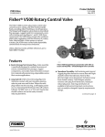
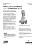
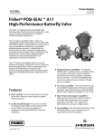
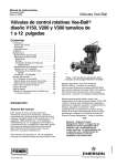
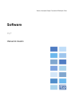
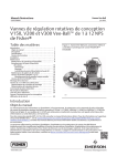
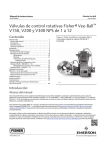
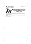
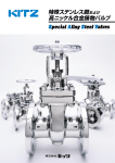
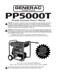
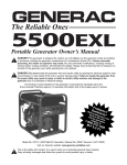
Product Bulletin
Vee-Ball Valves
51.3:Vee-Ball
January 2015
D101363X012
Fisherr Vee-Ball™
V150, V200 and V300 Rotary Control Valves
This bulletin covers the NPS 1 through 2, NPS 3
through 12 Series B, and the NPS 14 through 20 V150,
V200 and V300 Vee-Ball control valves. The Vee-Ball
valve combines globe valve ruggedness with the
efficiency of a rotary valve. A shearing action between
the V-notch ball and the ball seal (figure 1) promotes
smooth, nonclogging operation. The unrestricted
straight-through flow design provides high capacity for
gas, steam, liquids, and fibrous slurries.
V150, V200, and V300 valves mate with a variety of
ASME raised face flanges, as well as with EN flanges
(see Specifications).
To meet specific application requirements, a variety of
metal and soft ball seal materials are available. A
splined drive shaft combines with a variety of power
operated and manual actuators to provide reliable,
high-performance throttling or on-off operation for
many different applications in the process industries.
X0187
V150
Features
n Trim Versatility—Trim components are
interchangeable between V150, V200, and V300
valves. This feature allows you to reduce your spare
parts inventory and maintenance procedures. The
seal assembly can be changed without removing
the actuator or without removing the ball from the
valve body.
n Easy Installation—Flanged body design of the V150
and V300 eliminates exposed line flange bolting,
reduces alignment and installation time, and
promotes secure valve installations and piping
integrity.
www.Fisher.com
X0337
V200
Typical Vee-Ball Valves with Fisher 2052 Actuators and
FIELDVUEt DVC6200 Digital Valve Controllers
Product Bulletin
Vee-Ball Valves
51.3:Vee-Ball
January 2015
D101363X012
Specifications
(Forward Flow): Class IV per ANSI/FCI 70-2 and per IEC
60534-4,
HD (Heavy Duty) Metal Ball Seal (Bidirectional Flow):
0.01% of valve capacity; Class IV per ANSI/FCI 70-2
and IEC 60534-4; Maximum allowable pressure drop
in reverse flow is 6.9 bar (100 psi);
High Temperature HD (Heavy Duty) Metal Seal
(Bidirectional Flow): Class III per ANSI/FCI 70-2 and IEC
60534-4
Flow Ring Construction (Bidirectional Flow): 5% of
valve capacity at full travel
Micro-Notch Ball: Same leakage as standard ball
Valve Sizes and End Connection Styles
V150: NPS J 1, J 1-1/2, J 2, J 3, J 4, J 6, J 8,
J 10, J 12, flanged valves that mate with CL150
raised-face flanges (see table 1). Also, NPS 3 through
12 mate with PN classes (see table 1)
V150: NPS J 14, J 16 and J 20: Flanged raised-face
valves. NPS 14 and 16 valves are available in ASME
B16.10 Short, face-to-face dimensions only (see table
1 and figure 8)
V200: NPS J 1, J 1-1/2, J 2, J 3, J 4, J 6, J 8, or
J 10 flangeless valves that mate with J CL150,
J 300, or J 600 raised-face flanges depending on
size (see table 1)
Construction Materials
See tables 3 and 4
V300: NPS J 1, J 1-1/2, J 2, J 3, J 4, J 6, J 8,
J 10, J 12, J 14, and J 16 valves mate with CL300
raised-face flanges. Also some sizes mate with PN
classes (see table 1)
Temperature Capabilities(1,2)
Composition Seals
Fisher TCM Plus: -46 to 232_C (-50 to 450_F)
Fisher TCM Ultra: -46 to 260_C (-50 to 500_F)
HD Metal Seals: -46 to 288_C (-50 to 550_F)
High Temperature HD Metal Seal: 288 to 427_C (550
to 800_F). Contact your Emerson Process
Management sales office if higher temperatures are
required.
Ceramic Micro-Notch Ball: -46 to 93_C (-50 to
200_F)(4)
Flow Ring or Flat Metal Seal : -198 to 425_C (-325 to
800_F)
PEEK/PTFE Bearings: -198 to 260_C (-325 to 500_F)
Maximum Inlet Pressures(1)
V150 or V300 Steel, CF3M (316L Stainless Steel) or
CG8M (317 Stainless Steel) Valves: Consistent with
CL150 for V150, or CL300 for V300,
pressure-temperature ratings per ASME B16.34 or
with PN pressure-temperature ratings shown in table
1 but do not exceed the material temperature
capabilities shown below or the pressure drop
limitations. CF3M is available in all areas and is the
standard material offering in Europe.
V200 Steel and CG8M (317 Stainless Steel) Valves:
Consistent with applicable pressure-temperature
ratings in table 1 per ASME B16.34, but do not exceed
the material temperature capabilities shown below
and the pressure drop limitations.
Packing Constructions
PTFE V-ring: -46 to 232_C (-50 to 450_F)
Graphite: -198 to 538_C (-325 to 1000_F)
ENVIRO-SEALt Single PTFE V-ring: -46 to 232_C (-50
to 450_F)
ENVIRO-SEAL Graphite: -7 to 316_C (20 to 600_F)
CW2M Valves: Consistent with applicable
pressure-temperature ratings shown in table 5, but
do not exceed the material temperature capabilities
shown below and the pressure drop limitations.
Flow Characteristic
Modified equal percentage
Maximum Shutoff Pressure/Temperature Ratings(1)
Dimensions
Composition (Fisher TCM Plus or TCM Ultra), Flat
Metal (NPS 3 through 12 valves only), HD and High
Temperature HD Metal Ball Seals and Flow Ring: See
table 7.
See figures 5, 6, and 7 for dimensions
Optional Face-to-Face Dimensions
J ASME B16.10 short face-to-face dimensions are
Shutoff Classification(1)
available as an option for NPS 1 through 12 valves.
Note that ASME B16.10 short dimensions are actually
longer than ISA S75.08.02. See figure 8 for
dimensions.
Fisher TCM Plus or Ultra Ball Seal (Forward Flow):
Class VI per ANSI/FCI 70-2 and per IEC 60534-4,
Flat Metal Ball Seal for NPS 3 through 12 valves only
(continued)
2
Product Bulletin
Vee-Ball Valves
51.3:Vee-Ball
January 2015
D101363X012
Specifications (continued)
Standard Flow Direction
Forward (into the convex face of the V-notch ball)
Flow Coefficients
See Fisher Catalog 12
Valve/Actuator Action
With diaphragm or piston rotary actuator, the valve is
field-reversible between PDTC or PDTO:
J push-down-to-close (extending actuator rod closes
valve) and J push-down-to-open (extending actuator
rod opens valve)
Flow Coefficient Ratio(3)
See Fisher Catalog 12
Noise Levels
See Fisher Catalog 12
Maximum Ball Rotation
90 degrees
Actuator Mounting
Standard valve construction is for right-hand
mounting, as viewed from upstream end of valve.
Left-hand (optional) mounting is available upon
request.
Approximate Weight
See table 2
Options
J Pipe plug at end of follower shaft for all sizes,
J Line flange bolting, J Materials that are
compatible with sour service, J Alloy construction
materials, J ENVIRO-SEAL packing system: See figure
4 and Bulletin 59.3:041, ENVIRO-SEAL Packing
Systems for Rotary Valves (D101638X012) for more
information, J Micro-Notch construction for
NPS 1 valves (see Micro-Notch Construction section),
J S31254/CK3MCuN trim material
1. The pressure/temperature limits in this bulletin, and any applicable code or standard limitation, should not be exceeded.
2. Additional limits are shown in tables 5, 6 and 7.
3. Ratio of maximum flow coefficients to minimum usable flow coefficient can also be called rangeability.
4. For the CG8M and alloy 6 Micro-Notch constructions, pressure and temperature capabilities are the same as for standard constructions.
Features (continued)
n Application Versatility—The valves are available with
ISA S75.08.02 and IEC 534-3-2 face-to-face
dimensions as a standard construction, and
optional ASME B16.10 short face-to-face
dimensions. IEC 534.3.2 face-to-face dimensions are
equivalent to S75.08.02 face-to-face dimensions.
NPS 1 valve. See the Micro-Notch Construction
section of this bulletin for more information.
n Sour Service Capability—Materials are available for
applications involving sour liquids and gases. These
constructions comply with NACE MR0175-2002,
MR0175-2003, MR0103, and MR0175/ISO 15156.
n Quick and Easy Maintenance—Ball seal inspection
n Long Service Life—The solid HD metal seal (figures 1
and 2) construction provides long service life in
demanding applications. The constant wiping
action of the seal across the ball's sealing surface
prevents scale and sludge buildup, and provides
excellent service on steam, gases, slurries, and
various liquid applications.
and replacement is done at the valve body inlet
without removing the actuator or disassembling the
valve. Valve maintenance requires no special tools.
n Structural Integrity—One-piece valve body improves
structural integrity of the pressure boundary by
eliminating leak paths that could be caused by the
gaskets in two-piece, bolted valve designs.
n Smooth Valve Operation—Precision machined parts
and pressure balanced seal designs allow smooth,
precise movement of the ball.
n Excellent Flow Control—Precise contouring of the
Vee-Ball provides a modified equal percentage flow
characteristic. For very precise control of low flow
rates, the Micro-Notch option is available on the
n Exceptional Environmental Capabilities—The
optional ENVIRO-SEAL packing systems are
designed with very smooth shaft surfaces and live
loading to provide exceptional sealing. The seal of
the ENVIRO-SEAL system can restrict emissions to
less than the EPA (Environmental Protection
Agency) limit of 100 ppm (parts per million).
3
Product Bulletin
Vee-Ball Valves
51.3:Vee-Ball
January 2015
D101363X012
Table 1. Valve Body Materials, End Connections, and Ratings
VALVE DESIGN
VALVE BODY
MATERIAL
CF3M
EN STL 1.0619, EN SST
1.4581, or EN SST
1.4409(1)
SIZE
NPS
SIZE
RATINGS
DN
PN
1, 1-1/2, 2, 3, 4, 6, 8,
10, 12
CL150
---
---
---
---
DN 25, 40, 50, 80, 100,
150, 200, 250
PN 10/16
---
---
DN 300
PN 16
1, 1-1/2, 2, 3, 4, 6, 8,
10
CL150
DN 25, 40, 50, 80, 100,
150, 200, 250
PN 10/16
12, 16, 20
CL150
DN 300
PN 16
14
CL150
---
---
CG8M
1, 1-1/2, 2, 3, 4, 6, 8,
10, 12 and 14
CL150
---
---
CD3MN
1, 1-1/2, 2, 3, 4, 6, 8,
10 and 12
CL150
---
---
CD3MWCuN
1, 1-1/2, 2, 3, 4, 6, 8,
10 and 12
CL150
---
---
CK3MCUN
1, 1-1/2, 2, 3, 4, 6, 8,
10 and 12
CL150
---
---
CF3M
1, 1-1/2, 2
CL150/300/600
raised-face
3, 4
CL150 and CL300/600
raised-face
Not Available
Not Available
6, 8
CL150/300 and CL600
raised-face
WCC or CW2M
V150
WCC, CG8M, or CW2M
10
CL150 raised-face
CD3MN
1, 1-1/2, 2, 3, 4, 6, 8,
10 and 12
CL150, 300 and 600
---
---
CD3MWCuN
1, 1-1/2, 2, 3, 4, 6, 8,
10 and 12
CL150, 300 and 600
---
---
M35-1
1, 1-1/2, 2, 3, 4, 6, 8
CL150, 300 and 600
1, 1-1/2, 2, 3, 4, 6, 8
CL150, 300 and 600
Not Available
Not Available
10
CL150
CF3M
1, 1-1/2, 2, 3, 4, 6, 8,
10, 12
CL300
---
---
WCC or
CW2M
1, 1-1/2, 2, 3, 4, 6, 8,
10, 12, 14, 16
CL300
---
---
EN STL 1.0619, EN SST
1.4581, or EN SST
1.4409(1)
---
---
DN 25, 40, 50, 80, and
100
PN 25/40
CG8M
1, 1-1/2, 2, 3, 4, 6, 8,
10, 12, 14, 16
CL300
---
---
CD3MN
1, 1-1/2, 2, 3, 4, 6, 8,
10 and 12
CL300
---
---
CD3MWCuN
1, 1-1/2, 2, 3, 4, 6, 8,
10 and 12
CL300
---
---
M35-1
1, 1-1/2, 2, 3, 4, 6, 8
CL300
---
---
V200
CK3MCUN
V300
1. WCC and EN Stl 1.0619 are dual certified. CF3M and EN SST 1.4409 are dual certified.
4
RATINGS
Product Bulletin
Vee-Ball Valves
51.3:Vee-Ball
January 2015
D101363X012
Figure 1. Vee-Ball Construction Features, Seals (Fisher V150 Shown)
SEAL
PROTECTOR
RING
SEAL PROTECTOR
RING
BODY
HD SEAL
RADIAL
SEAL
SPRING
SEAL
FLAT
METAL
BALL
SEAL
V-NOTCH
BALL
W4713-3
SHIMS
BODY
VIEW A
FLAT METAL BALL SEAL DETAIL
FOR NPS 3 THROUGH 12
WAVE
SPRING
V-NOTCH BALL
W5704-1
VIEW A
HD METAL BALL SEAL DETAIL
SEAL PROTECTOR
RING
TCM
BALL SEAL
V-NOTCH
BALL
BODY
W6197-1
VIEW A
FISHER TCM PLUS BALL SEAL
NPS 1, 1-1/2, AND 2 VALVES
BACKUP
RING
SEAL
PROTECTOR
RING
SEAL
PROTECTOR RING
RETAINING
RINGS
PISTON
RING
PISTON RING
HD
METAL SEAL
WAVE
SPRING
HD
METAL
SEAL
WAVE
SPRING
RETAINING RING
(USE ONLY WHEN
ATTENUATOR IS
USED)
W8479
NPS 1, 1-1/2 & 2
HD METAL BALL SEAL
NPS 3 THROUGH 8 & NPS 14 THROUGH 20
HD METAL BALL SEAL
NPS 10 AND 12
HD METAL BALL SEAL
VIEW A
HIGH-TEMPERATURE HD METAL BALL SEAL
5
Product Bulletin
Vee-Ball Valves
51.3:Vee-Ball
January 2015
D101363X012
Figure 2. Vee-Ball Construction Features (Fisher V150 Shown)
V-NOTCH BALL
SEE VIEW A
(FIGURE 1)
SEAL
PROTECTOR
RING
GASKET
FOLLOWER
SHAFT
GROOVE PIN
BODY
DRIVE SHAFT
BEARING
TAPER KEY
PACKING FOLLOWER
W7435
NPS 3 THROUGH 12 VALVES
(HD BALL SEAL SHOWN)
HD METAL BALL SEAL
BOTTOM
FLANGE
PACKING FLANGE
AND PACKING FOLLOWER
PIN
W6099-1
6
NPS 14, 16, AND 20 VALVES
(HD METAL BALL SEAL)
Product Bulletin
Vee-Ball Valves
51.3:Vee-Ball
January 2015
D101363X012
Table 2. Valve Weights, Approximate
VALVE SIZE, NPS
V150
V200
V300
kg
lbs
kg
lbs
kg
lbs
1
5.6
13
4.5
10
8
17
1-1/2
8.2
19
6.4
14
12
27
2
9.1
21
10
23
17
38
3
13
43
15
34
28
61
4
26
57
22
48
37
81
6
42
93
36
80
60
133
8
72
158
62
136
103
226
10
107
235
114
252
200
440
12
157
347
---
---
293
645
14
247
545
---
---
374
825
16
333
735
---
---
510
1125
20
524
1155
---
---
---
---
Series B
NPS 3 through 12 have been changed to reduce parts
and to improve control performance. The V-notch Ball
now resembles the NPS 14 through 20 V-notch Ball.
The pressed-in bushings have been eliminated, as well
as the thrust washer.
Figure 3. Typical Micro-Notch Ball and Shaft
MICRONOTCH
VEE BALL
Micro-Notch Construction
For very precise control of low flow rates, the
Micro-Notch construction (see figure 3) is available on
NPS 1 valves. Three Micro-Notch ball materials are
available: chrome-plated CG8M (317 stainless steel),
solid alloy 6, and solid VTC ceramic. A VTC ceramic HD
seal is standard with the VTC ceramic ball. For the
CG8M and alloy 6 constructions, pressure and
temperature capabilities are the same as for standard
constructions. For the ceramic construction,
maximum temperature is 93_C (200_F).
DRIVE SHAFT
W6256
For further information, please refer to the Fisher
Vee-Ball V150, V200 and V300 Rotary Control Valves
NPS 1 through 12 instruction manual (D101554X012).
7
Product Bulletin
Vee-Ball Valves
51.3:Vee-Ball
January 2015
D101363X012
Table 3. Materials of Construction for NPS 1 through 12 Valves
PART
MATERIAL
Valve Body and Seal
Protector Ring or
Flow Ring
WCC steel (EN 1.0619), CG8M (317 SST), CF3M(1) (316L SST EN 1.4409 or optional
EN 1.4581), CD3MN, CD3MWCuN, CW2M (CW2M valve available with Fisher TCM Plus
seal only), M35-1 or CK3MCuN
Backup Ring (NPS 1, 1-1/2 and 2 only)
CG8M, CF3M(1), or CW2M
V-Notch Ball
CG8M, CF3M, CW2M, chromium-plated CF3M, chromium-plated CG8M and
chromium-plated CG8M1/2 CF3M with alloy 6 notch, chromium-plated CD3MN,
chromium-plated CD3MWCuN, M35-1, or CK3MCuN
Seal
Fisher TCM
Fisher TCM Plus and Fisher TCM Ultra
Flat Metal Seal, Shims, and Spring Seal(7)
Spring Tempered S31600 (316 stainless steel) or
Spring Tempered S30200 (302 stainless steel) for NPS 12 valves only
HD (Heavy-Duty) Metal
CF10SMnN(2) , CD7MCuN(3) (alloy 255
duplex stainless steel) or R30006 (Alloy 6)
High Temperature HD Metal Seal
R30006 (Alloy 6)
Wave Spring (use with HD seal)
N07750
HD Seal Radial Seal
Graphite reinforced PTFE
High Temp HD Seal Piston Ring
Graphite FMS 17F39
Bearings
PEEK(4)/Carbon-filled PTFE liner, S31603 Nitride,
R30006 (alloy 6), silver-plated R30006,
N10276 with carbon-filled PTFE liner, or N10276 with glass-filled PTFE liner
Seal Retainer Gasket
Laminated graphite
Packing
PTFE V-ring with one carbon-filled PTFE ring(5), PTFE V-ring, or
graphite ribbon. Packing is available with or without live loading.
Shafts
S20910, S17400 (17-4PH stainless steel),
N10276, N05500, S31254(8), or S32760(8)
Groove Pin
S31600 or N10276
Taper Key
R30006(6), S20910, or N10276
Taper Pin (NPS 1, 1-1/2, and 2 only)
S20910 or N10276
Pipe Plug (Optional)
S31600 N10276, or S31603 (316L stainless steel)
Seal Retainer Screws and Washers
Stainless steel
Packing Follower and Packing Box Ring
CF8M (316 stainless steel), N10276, S312254, or N10276
with separate S31600 packing box flange
Actuator Mounting Bolts and Nuts
Grade 5 steel or strain-hardened B8M stainless steel
Spacer and Bushing
S31700, N10276, or S31603
Packing Follower Bolting and Optional Line Bolting
SA-193-B7, SA-193-B7M, or strain-hardened SA-193-B8M
1. CF3M is available in all areas as a special order and is the standard material offered in Europe.
2. Recommended for lubricated and non-lubricated service and where corrosion properties similar to 304 stainless steel are acceptable.
3. Recommended for lubricated service and where corrosion properties equal to or better than 317 stainless steel are required.
4. PEEK is poly-ether-ether-ketone.
5. The carbon-filled PTFE ring is used for grounding.
6. Standard material offered in North America.
7. Offered for lubricated service only.
8. S31254 and S32760 shafts may cause the valve to be derated. Contact your Emerson Process Management sales office.
8
Product Bulletin
Vee-Ball Valves
51.3:Vee-Ball
January 2015
D101363X012
Table 4. Materials of Construction for NPS 14, 16 and 20 Valves
Part
Material
Valve Body, Seal Protector Ring, and Flow Ring
WCC steel or CG8M (317 stainless steel)
V-Notch Ball
Chromium-plated CG8M, CG8M, Chromium-plated CG8M with alloy 6 notch
Ball Seal
Fisher TCM
Fisher TCM Plus and Fisher TCM Ultra
HD (Heavy-Duty Metal)
CF10SMnN(1) , CD7MCuM(2) (alloy 225 duplex stainless steel) or R30006 (alloy 6)
Wave Spring (use with HD seal)
N07750
Radial Seal (use with HD seal)
PTFE with N10276 spring
Bearings
PEEK/PTFE(3), S44004 (440C stainless steel--use with S17400 [17-4PH stainless steel]
shafts, alloy 6B, and silver plated alloy 6B
Thrust Washer (use with metal bearings)
Alloy 6B
Seal Retainer Gasket
Laminated Graphite
Packing
PTFE V-ring with one conductive V-ring(4), PTFE V-ring, or graphite ribbon
Shafts
S17400 (17-4 stainless steel) or S20910
Pins
S20910
Pipe Plug
S31700 (317 stainless steel)
Packing Follower Bolting
B7M steel or strain-hardened B8M stainless steel
Retainer Screw
B8M stainless steel
Packing Follower and Packing Box ring
S31600 (316 stainless steel)
Packing Flange
Steel or S31600
Actuator Mounting Bolts and Nuts
Grade 5 steel or strain-hardened B8M stainless steel
Gasket (used with bottom flange)
S31603 (316L stainless steel) spiral wound
Stud and Hex Nut (used with bottom flange)
B7 steel or strain-hardened B8M stainless steel
1. Recommended where corrosion properties similar to 304 stainless steel are acceptable.
2. Recommended for lubricated service and where corrosion properties equal to or better than S31700 stainless steel.
3. PEEK (Poly-ether-ether-ketone) w/PTFE liner.
4. A carbon-filled PTFE ring is used for grounding.
Figure 4. Typical ENVIRO-SEAL Packing Arrangements
PACKING
BOX STUD
SPRINGS
PACKING
FLANGE
VALVE
BODY
ANTIEXTRUSION
RINGS
VALVE
SHAFT
PACKING
FLANGE
PACKING
BOX RING
PTFE
PACKING
V-RINGS
SHOWN
PACKING
FOLLOWER
W5806-2
PTFE PACKING
VALVE
SHAFT
SPRINGS
PACKING
FOLLOWER
PACKING
BOX
RING
GRAPHITE
PACKING
SET
W6125-1
GRAPHITE PACKING
9
Product Bulletin
Vee-Ball Valves
51.3:Vee-Ball
January 2015
D101363X012
Table 5. Maximum Allowable Inlet Pressure for CW2M and CG8M (317 Stainless Steel) Valves, CL150(1)
TEMPERATURE
CW2M
_C
CG8M
TEMPERATURE
CW2M
CG8M
_F
Psig
Psig
Bar
-29 to 38
93
149
204
232
20.0
17.9
15.9
13.8
12.8
19.0
16.2
14.8
13.4
12.6
-20 to 100
200
300
400
450
290
260
230
200
185
275
235
215
195
183
260
316
343
371
399
427
-------------
11.7
9.6
8.6
7.6
6.5
5.5
500
600
650
700
750
800
-------------
170
140
125
110
95
80
1. These materials are not listed in ASME B16.34. The designation 150 is used only to indicate relative pressure-retaining capabilities and is not an ASME pressure-temperature rating class
designation.
Pressure Drops
limitations. Information on limits for S31254, CW2M,
M35-1, CD3MN, CD3MWCuN, and other alloy
constructions can be obtained by contacting your
Emerson Process Management sales office. The lowest
number from the tables is the appropriate limit. The
tables for both trim and body limits must be
consulted.
Pressure drop limits of any given valve are based on
valve body, and trim material limits. To find the
appropriate pressure drop limitation, choose the
desired valve size and temperature range. Then search
table 6 for body limitations and table 7 for trim
Table 6. Maximum Allowable Shutoff Pressure Drops (Body Ratings) based on Carbon Steel and Stainless Steel Valve
Body Types. (The tables for both trim and body limits must be consulted.)
TEMPERATURE
RANGE
PRESSURE CLASS
WCC
CL150
316L SST
CL150
317 SST
CL150
WCC
CL300
316L SST
CL300
-46 to -29
WCC
CL600
316L SST
CL600
317 SST
CL600
---
15.9
19.0
---
41.4
-29 to 38
20.0
15.9
19.0
51.7
41.4
49.6
---
82.7
99.3
49.6
103
82.7
93
17.9
13.4
16.2
51.7
99.3
34.8
42.7
103
70.0
149
15.9
12.1
14.8
85.5
50.3
31.4
38.6
100
62.7
204
13.8
11.0
77.2
13.4
48.6
28.6
35.5
97.2
56.9
232
12.8
70.6
10.7
12.8
47.2
27.9
34.5
94.5
54.8
260
68.6
11.7
10.0
11.7
45.9
26.2
33.1
91.7
52.7
65.8
316
10.7
9.9
10.7
43.8
25.5
32.1
87.6
51.0
64.1
343
9.65
9.7
8.62
41.7
23.8
31.0
83.4
49.6
62.4
371
8.62
8.6
7.58
40.7
23.8
30.7
81.0
48.3
60.0
399
6.55
6.6
6.55
34.8
23.1
29.3
69.6
46.2
58.9
427
5.52
5.5
5.52
28.3
22.8
29.0
56.9
45.5
58.3
_C
Bar
_F
10
317 SST
CL300
Psi
-50 to -20
---
230
275
---
600
720
---
1200
1440
-20 to 100
290
230
275
750
600
720
1500
1200
1440
200
260
195
235
750
505
620
1500
1015
1240
300
230
175
215
730
455
560
1455
910
1120
400
200
160
195
705
415
515
1410
825
1025
450
185
155
185
685
405
500
1370
795
995
500
170
145
170
665
380
480
1330
765
955
550
155
143
155
635
370
465
1270
740
930
600
140
140
140
605
360
450
1210
720
905
650
125
125
125
590
350
445
1175
700
890
700
110
110
110
570
345
430
1135
685
870
750
95
95
95
505
335
425
1010
670
855
800
80
80
80
410
330
420
825
660
845
Product Bulletin
Vee-Ball Valves
51.3:Vee-Ball
January 2015
D101363X012
Table 7. Maximum Allowable Shutoff Pressure Drops based on Trim (Bearing and Seal).
(Note: Do not exceed the PN or ASME pressure/temperature rating of the valve or mating flanges.)
VALVE SIZE, NPS
BEARING
MATERIAL
TEMPERATURE
RANGE, _C
1
-46 to 38
51.7
51.7
51.7
51.7
51.7
93
37.9
37.9
37.9
37.9
37.9
149
24.1
24.1
24.1
24.1
204
10.3
10.3
10.3
232
3.45
3.45
HD Metal(1)
-46 to 260
51.7
Flat Metal(2)
-73 to 260
Flow Ring
260
BALL SEAL
Fisher TCM Plus or
Ultra
PEEK/PTFE
R30006
R30006 Silver
Plated
S31603L Nitride
BEARING
MATERIAL
S31603L Nitride
3
4
6
8
10
12
14
16
20
51.7
51.7
40.2
37.6
31.0
23.8
31.0
37.9
37.9
37.9
37.6
31.0
23.8
31.0
24.1
24.1
24.1
24.1
24.1
24.1
23.8
24.1
10.3
10.3
10.3
10.3
10.3
10.3
10.3
10.3
10.3
3.45
3.45
3.45
3.45
3.45
3.45
3.45
3.45
3.45
3.45
51.7
51.7
51.7
51.7
51.7
51.7
40.9
38.1
31.0
26.5
31.0
---
---
---
20.7
20.7
20.7
20.7
10.3
10.3
---
---
---
103.4
103.4
103.4
103.4
72.4
75.2
73.8
40.5
37.7
40.5
35.0
44.7
51.7
50.0
25.7
17.5
Bar
HD Metal(1)
-46 to 288
228 to 427
Flat Metal(2)
-73 to 427
---
---
---
Flow Ring
427
74.5
49.6
26.8
51.7
51.7
51.7
11.0
10.9
11.2
6.14
5.72
6.14
7.52
6.83
8.3(3)
8.2(3)
8.4(3)
4.6(3)
4.3(3)
---
---
---
17.0
10.1
10.7
10.6
5.86
5.52
---
---
---
18.8
10.9
11.2
11.1
6.07
5.65
6.07
7.31
6.69
35.0
22.1
21.8
22.5
38.3(3) 37.5(3) 19.3(3) 13.2(3)
HD Metal(1)
-46 to 288
High Tem HD
Metal(1)
228 to 427
Flat Metal(2)
-73 to 427
---
---
Flow Ring
427
103.4
103.4
12.3
11.4
12.3
13.2
13.7
38.3(3) 38.3(3) 38.3(3) 26.3(3) 16.5(3) 16.3(3) 16.9(3)
9.2(3)
8.6(3)
---
---
---
---
20.7
20.1
20.7
20.7
10.3
10.3
---
---
---
53.5
37.6
21.8
22.5
22.2
12.1
11.3
12.1
14.6
13.4
51.7
36.7
36.3
37.4
20.5
19.1
---
---
---
---
---
---
HD Metal(1)
-46 to 288
51.0
51.0
51.0
High Temp HD
Metal(1)
228 to 427
---
---
---
Flat Metal(2)
-73 to 427
---
---
---
20.7
20.7
20.7
20.7
10.3
10.3
---
---
---
Flow Ring
427
99.3
99.3
88.9
62.7
36.3
37.4
37.0
20.2
18.8
---
---
---
BALL SEAL
TEMPERATURE
RANGE, _F
38.3(3) 27.6(3) 27.2(3) 28.1(3) 15.4(3) 14.3(3)
Psi
-50 to 100
750
750
750
750
750
750
750
583
545
450
345
450
200
550
550
550
550
550
550
550
550
545
450
345
450
300
350
350
350
350
350
350
350
350
350
350
345
350
400
150
150
150
150
150
150
150
150
150
150
150
150
450
50
50
50
50
50
50
50
50
50
50
50
50
HD Metal(1)
-50 to 500
750
750
750
750
750
750
750
593
553
450
384
450
Flat Metal(2)
-100 to 500
---
---
---
300
300
300
300
150
150
---
---
---
Flow Ring
500
1500
1500
1500
1500
1050
1090
1070
587
547
587
508
648
HD Metal(1)
PEEK/PTFE
R30006 Silver
Plated
2
High Temp HD
Metal(1)
Fisher TCM Plus or
Ultra
R30006
1-1/2
-50 to 550
750
725
373
254
160
158
163
89
83
89
109
99
High Temp HD
Metal(1)
550 to 800
555(3)
544(3)
280(3)
191(3)
120(3)
119(3)
122(3)
67(3)
62(3)
---
---
---
Flat Metal(2)
-100 to 800
---
---
---
246
146
155
154
85
80
---
---
---
Flow Ring
800
1080
720
388
273
158
163
161
88
82
88
106
97
HD Metal(1)
-50 to 550
750
750
750
508
320
316
326
178
166
178
192
198
High Temp HD
Metal(1)
550 to 800
555(3)
555(3)
555(3)
381(3)
240(3)
237(3)
245(3)
134(3)
125(3)
---
---
---
Flat Metal(2)
-100 to 800
---
---
---
300
292
300
300
150
150
---
---
---
Flow Ring
800
1500
1500
776
546
316
326
322
176
164
176
212
194
HD Metal(1)
-50 to 550
740
740
740
750
533
527
543
297
277
---
---
---
High Temp HD
Metal(1)
550 to 800
---
---
---
555(3)
400(3)
395(3)
407(3)
223(3)
208(3)
---
---
---
Flat Metal(2)
-100 to 800
---
---
---
300
300
300
300
150
150
---
---
---
Flow Ring
800
1440
1440
1290
910
527
543
537
293
273
---
---
---
1. Pressure drops shown for HD metal seals are for forward flow only. For reverse flow with HD metal seal, limit pressure drop to 6.9 bar (100 psig).
2. Lubricated service only.
3. Consult your Emerson Process Management sales office if higher pressure drops are required.
11
Product Bulletin
Vee-Ball Valves
51.3:Vee-Ball
January 2015
D101363X012
Table 8. Fisher V150 Dimensions
VALVE
SIZE
V150 DIMENSIONS (ISA S75.08.02)(1)
N(3)
S
Diameter
T
U
W
79
92
100
73
80
87
13
15.9 and 15.9 x 12.7
15.9 and 15.9 x 12.7
117
---
14.2
130
141
164
106
119
127
100
100
114
19.1
19.1
25.4
152
31.8
14.2
14.2
17.5
184
222
268
232
260
303
133
146
152
127
133
133
31.8
31.8
38.1
235
46.0
17.5
7.38
3.19
3.38
4.19
3.75
4.75
5.00
3.12
3.62
3.94
2.88
3.12
3.44
1/2
5/8 and 5/8 x 1/2
5/8 and 5/8 x 1/2
4.62
---
0.56
3.10
3.99
4.29
8.44
4.62
5.25
5.94
5.12
5.56
6.44
4.19
4.69
5.00
3.94
3.94
4.50
3/4
3/4
1
6.00
1.25
0.56
0.56
0.69
9.56
11.69
13.31
4.88
5.77
6.87
8.19
7.69
8.75
10.56
9.12
10.25
11.94
5.25
5.75
6.00
5.00
5.25
5.25
1-1/4
1-1/4
1-1/2
9.25
1.81
0.69
15.00
16.00
20.00
8.12
9.00
9.25
14.00
11.62
13.00
16.00
13.50
14.38
18.00
6.00
6.00
7.00
5.25
5.25
6.25
1-3/4
2-1/8
2-1/2
10.75
10.75
13.25
2.00
2.00
3.00
0.75
0.75
0.88
D
G
K
M(3)
56
62
67
188
83
90
87
95
121
127
165
194
229
79
101
109
214
100
133
151
243
297
338
124
147
174
208
1
1-1/2
2
4.00
4.50
4.88
2.21
2.46
2.63
3
4
6
6.50
7.62
9.00
8
10
12
14(2)
16(2)
20
A
B
25
40
50
102
114
124
80
100
150
200
250
300
DN
mm
NPS
Inch
1. Inlet flange stud bolt length is longer than the standard length specified in ASME B16.5. See dimension M below.
2. NPS 14 and 16 valves are available in ASME B16.10 short, only. See dimension A for ASME B16.10 short shown in figure 8.
3. Clearance necessary to remove flange bolts.
Figure 5. Fisher V150 Dimensions (also see table 8)
MATCHES
CL150
RF FLANGES OR
PN 10 AND 16
U
S DIA
N
M
B
A
11B2625-K
B2153-5
12
G
K
D
T
T
W
W
NPS 1 THROUGH 2
NPS 3 THROUGH 20
Product Bulletin
Vee-Ball Valves
51.3:Vee-Ball
January 2015
D101363X012
Table 9. Fisher V200 Dimensions
V200 DIMENSIONS (ISA S75.08.02)
VALVE
SIZE, NPS
A
B
1
102
56
1-1/2
114
62
2
124
3
4
6
D
G
K
81
M
R
R1
202
51
102
12.7
224
224
73
119
15.7 and 15.7 x 12.7
211
236
236
92
137
15.7 and 15.7 x 12.7
130
141
164(1)
254
286
343
279
305
362
286
343
413
127
157
216
167
197
260
19.1
19.1
25.4
152
32
14.2
195
232
343
387
426
270
314
222
260
419
---
---
324
368
31.8
235
46
17.5
4.62
---
0.56
CL150
CL300
CL600
95
176
202
89
121
189
67
106
127
165
194
229
79
101
109
117
133
159
8
243
124
10
297
147
S
T
U
W
117
---
14.2
ASME B16.5
RF FLANGES
mm
188
214
208
CL150, 300,
and 600
CL150
Inch
1
4.00
2.21
1-1/2
4.50
2.46
3.19
3.75
6.94
7.94
7.94
2
4.00
1/2
3.50
4.75
7.44
8.81
8.81
2.88
4.68
5/8 and 5/8 x 1/2
2
4.88
2.63
4.19
5.00
8.31
9.31
9.31
3.63
5.38
5/8 and 5/8 x 1/2
3
4
6
6.50
7.62
9.00
3.10
3.99
4.29
4.62
5.25
6.25
5.12
5.56
6.44(1)
10.00
11.25
13.50
11.00
12.00
14.25
11.25
13.50
16.25
5.00
6.19
8.50
6.56
7.76
10.24
3/4
3/4
1
6.00
1.25
0.56
8
9.56
4.88
7.69
9.12
13.50
15.25
16.75
10.63
12.38
10
11.69
5.77
8.75
10.25
16.50
---
---
12.75
14.50
1-1/4
9.25
1.81
0.69
7.38
8.44
8.19
CL150 and
300
CL150
1. 179 mm (7.06 inches) for NPS 6, CL600 valves only.
Figure 6. Fisher V200 Dimensions (also see table 9)
A
G
B
K
U
D
R∅
S∅
T
T
R1
W
NPS 1 THROUGH 2
W
NPS 3 THROUGH 20
11B2625-K
12B3060-L
B2331-2
M
13
Product Bulletin
Vee-Ball Valves
51.3:Vee-Ball
January 2015
D101363X012
Table 10. Fisher V300 Dimensions
VALVE
SIZE,
V300 DIMENSIONS (ISA S75.08.02)
N(2)
S
Diameter
T
U
100
114
106
94
108
100
13
16 and 16 X 13
16 and 16 X 13
117
---
130
141
164
133
140
152
121
127
140
19
19
25
152
32
195
222
268
232
260
303
165
186
198
152
173
186
32
32
38
235
46
17.5
356
295
343
197
178
44.5
273
50.8
19.5
356
338
356
210
191
53.8
273
50.8
19.5
7.38
3.19
3.50
4.19
3.75
4.75
5.00
3.94
4.50
4.19
3.69
4.25
3.94
1/2
5/8 and 5/8 X 1/2
5/8 and 5/8 X 1/2
4.62
---
3.10
3.99
4.29
8.44
4.62
5.25
6.25
5.12
5.56
6.44
5.25
5.50
6.00
4.75
5.00
5.50
3/4
3/4
1
6.00
1.25
9.56
11.69
13.31
4.88
5.77
6.87
8.19
7.69
8.75
10.56
9.12
10.25
11.94
6.50
7.31
7.81
6.00
6.81
7.31
1-1/4
1-1/4
1-1/2
9.25
1.81
0.69
15.00
16.00
8.12
9.00
14.00
14.00
11.62
13.31
13.50
14.38
7.75
8.25
7.00
7.50
1-3/4
2-1/8
10.75
2.00
0.75
D
G
K
M(2)
188
81
89
106
95
121
127
79
101
109
214
117
133
159
243
297
338
124
147
174
208
356 mm
(14-in.)
381
206
406 mm
(16-in.)
406
228
1
1-1/2
2
4.00
4.50
4.88
2.21
2.46
2.63
3
4
6
6.50
7.62
9.00
8
10
12
14
16
A
B
25
40
50
102
114
124
56
62
67
80
100
150
165
194
229
200
250
300
DN(1)
W
mm
NPS
14.2
Inch
0.56
1. DN25, 40, 50, 80, and 100 are the only sizes offered in V300 for Europe.
2. Clearance necessary to remove flange bolts.
Figure 7. Fisher V300 Dimensions (also see table 10)
MATCHES CL300 RF
OR PN 25, 40 FLANGES
U
S∅
T
N
B2330-3
14
B
A
M
G
K
D
T
W∅
W∅
NPS
NPS
1 THROUGH 2 3 THROUGH 12
Product Bulletin
Vee-Ball Valves
51.3:Vee-Ball
January 2015
D101363X012
Table 11. Fisher V150 Optional Dimensions
Table 12. Fisher V200 Optional Dimensions
V200 OPTIONAL DIMENSIONS (ASME B16.10 SHORT)(1,2)
V150 OPTIONAL DIMENSIONS FOR NPS 1 THROUGH 12
(ASME B16.10 SHORT)
A
M
VALVE SIZE, NPS
A
N
VALVE
SIZE, NPS
mm
Inches
mm
Inches
mm
Inches
1
1-1/2
2
3
4
6
8
10
12
127
165
178
203
229
267
292
330
356
5.00
6.50
7.00
8.00
9.00
10.50
11.50
13.00
14.00
103
135
155
142
155
163
182
176
170
4.06
5.31
6.11
5.61
6.11
6.40
7.15
6.94
6.69
71
78
92
98
98
112
124
132
132
2.81
3.06
3.61
3.86
3.86
4.40
4.90
5.19
5.19
M
mm
1
1-1/2
2
3
4
6
8
10
127
165
178
203
229
267
292
330
1
1-1/2
2
3
4
6
8
10
5.00
6.50
7.00
8.00
9.00
10.50
11.50
13.00
202
240
268
286
321
381
394
451
Inch
7.94
9.44
10.56
11.25
12.62
15.00
15.50
17.75
1. Available for CL150 valves only.
2. ASME B16.10 short dimensions are actually longer than ISA S75.08.02 dimensions.
Figure 8. Fisher V150 and V200 Optional Dimensions (also see tables 11 and 12)
N
14B6907
M
N
A
A
A
ASME B16.10 SHORT
NPS 14 AND 16 V150
M
11B2625-D
B2424-1
ASME B16.10 SHORT
NPS 1 THROUGH 12 V150
12B3060-B
A6530
M
ASME B16.10 SHORT
V200
Notes:
S NPS 1 through 12 valves are available with either ISA S75.08.02 face-to-face dimensions or ASME B16.10 short face-to-face dimensions. NPS 1 through 12 valves will be
supplied in ISA S75.08.02 unless you specify otherwise. Note that ASME B16.10 short dimensions are actually longer than ISA S75.08.02.
S NPS 14 and 16 valves are available only with ASME B16.10 short face-to-face dimensions.
S NPS 20 valves are available only with a 508 mm (20-inch) face-to-face dimension.
S M and N dimensions shown for V150 are clearance necessary to remove flange bolts.
15
Product Bulletin
51.3:Vee-Ball
January 2015
Vee-Ball Valves
D101363X012
Neither Emerson, Emerson Process Management, nor any of their affiliated entities assumes responsibility for the selection, use or maintenance
of any product. Responsibility for proper selection, use, and maintenance of any product remains solely with the purchaser and end user.
Fisher, Vee-Ball, FIELDVUE, and ENVIRO-SEAL are marks owned by one of the companies in the Emerson Process Management business unit of Emerson
Electric Co. Emerson Process Management, Emerson, and the Emerson logo are trademarks and service marks of Emerson Electric Co. All other marks are
the property of their respective owners.
The contents of this publication are presented for informational purposes only, and while every effort has been made to ensure their accuracy, they are not
to be construed as warranties or guarantees, express or implied, regarding the products or services described herein or their use or applicability. All sales are
governed by our terms and conditions, which are available upon request. We reserve the right to modify or improve the designs or specifications of such
products at any time without notice.
Emerson Process Management
Marshalltown, Iowa 50158 USA
Sorocaba, 18087 Brazil
Chatham, Kent ME4 4QZ UK
Dubai, United Arab Emirates
Singapore 128461 Singapore
www.Fisher.com
E
161990, 2015 Fisher Controls International LLC. All rights reserved.