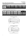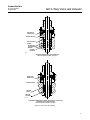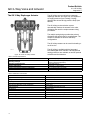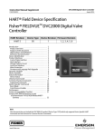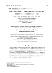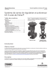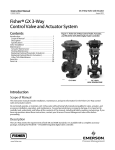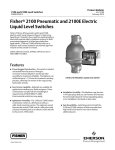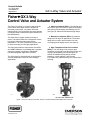
1
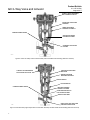
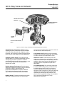
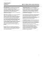
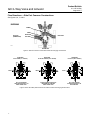
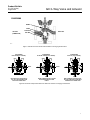
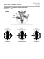
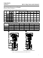
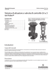
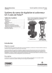
Product Bulletin
51.1:GX 3--Way
D103305X012
August 2011
GX 3--Way Valve and Actuator
Fisherr GX 3-Way
Control Valve and Actuator System
The Fisher GX 3-Way is a compact, state-of-the-art
control valve and actuator system, designed to
accurately control water, oils, steam, and other
industrial fluids. The robust GX 3-way valve package
is perfectly suited to address the space limitations of
the OEM industry.
The GX 3-Way is rugged, reliable, and easy to
select. The internal valve trim is designed to ensure
long service life and avoiding unnecessary
maintenance. The same construction may be used
for both converging and diverging applications.
The GX 3-Way meets the requirements of both EN
and ASME standards. It is available with a complete
accessory package, including the FIELDVUEt
DVC2000 integrated digital valve controller.
The GX 3-Way trim characteristics are designed for
accurate temperature control in heat exchanger
applications.
W9557
D Side-Port Common (SPC)-- --The side flange is
the common pipe connection for general converging
(flow-mixing) and diverging (flow-splitting) service
(see figure 5). Utilizes an unbalanced plug design.
D Bottom-Port Common (BPC)-- --A balanced
design used for high nP applications. The bottom
flange is the common pipe connection for both
converging and diverging service (see figure 9).
D High--Temperature Side--Port Common
(SPC)-- -- The side flange is the common pipe
connection for general converging (flow-mixing) and
diverging (flow-splitting) service (see figure 3).
Utilizes an unbalanced plug design, a stem
extension, a yoke extension, and includes
live--loaded ULF graphite packing and a hard--faced
seat ring.
GE49204
X0176
GX 3--WAY
GX 3--WAY HIGH--TEMPERATURE
Figure 1. Fisher GX 3-Way Control Valve, Actuator, and FIELDVUE DVC2000 Digital Valve Controller
www.Fisher.com
Product Bulletin
51.1:GX 3--Way
August 2011
GX 3--Way Valve and Actuator
COMPACT FIELD-REVERSIBLE
MULTI-SPRING ACTUATOR
INTEGRATED POSITIONER
MOUNTING
NAMUR POSITIONER
MOUNTING CAPABILITY
CLAMPED BONNET DESIGN
ONE-PIECE SCREWED
PACKING FOLLOWER
STANDARD LIVE-LOADED
PACKING
W9578-1
Figure 2. Fisher GX 3-Way Control Valve Assembly with Port-Guided Contoured Plug (Side Port Common)
COMPACT FIELD-REVERSIBLE
MULTI-SPRING ACTUATOR
INTEGRATED POSITIONER
MOUNTING
NAMUR POSITIONER
MOUNTING CAPABILITY
STEM EXTENSION
YOKE EXTENSION
CLAMPED BONNET DESIGN
ONE-PIECE SCREWED
PACKING FOLLOWER
STANDARD GRAPHITE ULF
LIVE-LOADED PACKING
GRAPHITE SEAL RING
X0094--1
HARD--FACED SEAT AND GUIDE
SURFACES ON SEAT RING
Figure 3. Fisher GX 3-Way High--Temperature Control Valve Assembly with Port-Guided Contoured Plug (Side Port Common)
2
Product Bulletin
51.1:GX 3--Way
August 2011
Contents
Features . . . . . . . . . . . . . . . . . . . . . . . . . . . . . . . . .
Principle of Operation . . . . . . . . . . . . . . . . . . . . .
GX 3-Way Control Valve Specifications
and Materials of Construction . . . . . . . . . . .
The GX 3-Way Diaphragm Actuator . . . . . . . .
Valve-Actuator Dimensions and Weights . . . .
GX 3-Way Actuator Accessories . . . . . . . . . . .
The FIELDVUE DVC2000
Digital Valve Controller . . . . . . . . . . . . . . . . .
Optional Positioners and Instruments . . . . . . .
Coefficients . . . . . . . . . . . . . . . . . . . . . . . . . . . . .
Features
D Easy to size and select
D No actuator sizing required--selection is
automatic
D Engineered for easy maintenance
D Maximum part commonality across sizes
GX 3--Way Valve and Actuator
D Replaceable trim
3
10
11
14
17
19
19
20
21
D Low lifetime costs
D Robust, low-profile design
D Available with integrated, easy-to-calibrate
DVC2000 digital valve controller
D Valve body sizes DN 25 to DN 100
(NPS 1 through 4)
D Pressure Classes PN 10-40,
CL150 and 300
D High capacity design
D Valve body flow passage optimized for flow
stability
D Shutoff capabilities: Class IV metal to metal
D ISO 5210 F7 mounting available for use with
electric actuators
3
Product Bulletin
51.1:GX 3--Way
August 2011
GX 3--Way Valve and Actuator
LINKAGE-LESS POSITION
FEEDBACK
INTEGRAL PNEUMATIC
PASSAGEWAYS
DVC2000
COVER
PUSH-BUTTON INSTRUMENT
SETUP
Figure 4. Fisher GX 3-Way and FIELDVUE DVC2000 Digital Valve Controller
Optimized valve and actuator system. Product
simplicity and ease of selection form the foundation
of the GX 3-Way. Mounted with a digital or analog
positioner, the GX 3-Way provides high performance
control across a wide range of process applications.
across sizes. The actuator stem and stem connector
are used across all GX 3-Way sizes.
Compact actuator design. The multi-spring GX
3-Way actuator is a compact robust design. The GX
3-Way design has been optimized to eliminate
complicated 3-way actuator sizing procedures - once
the valve body and port size are selected, the
actuator size is fixed.
Stable flow control. The flow cavity of the GX
3-Way valve body has been engineered to provide
stable flow and reduce process variability. This linear
stability for both converging and diverging flow is
perfectly suited for temperature and pH control
applications.
Reliable Actuator Performance. Special actuator
diaphragm material helps reduce common problems
such as air oxidation, thermal aging, low
temperature embrittlement, and loss of retention.
The double-sided diaphragm within the actuator
helps eliminate mechanical wear-induced failure.
Modular design. The design architecture has been
optimized to maximize the use of common parts
4
Low lifetime costs. Reduced product complexity,
low parts count, and part commonality all contribute
to reduced inventory and maintenance costs.
Live-loaded packing. The GX 3-Way comes with
live-loaded PTFE V-ring packing as standard. The
live-loaded design helps to seal your process to
conserve valuable process fluid, while reducing
emissions to the environment. The long-life and high
reliability of the live-loaded system also reduces
maintenance costs and process downtime. ULF
(ultra low friction) graphite packing is also available
for all sizes and is standard on HT (high
temperature) construction.
Product Bulletin
51.1:GX 3--Way
August 2011
Easy maintenance. The simple screwed seat-ring
and one-piece plug and stem design provide easy
maintenance. Design simplicity and parts
commonality contribute to reduced spares inventory.
The integrated DVC2000 digital valve controller
allows easy instrument removal, without a
requirement for tubing disconnection or replacement
(fail-down construction).
Digital valve controller. The GX 3-Way is available
with the DVC2000 digital valve controller. The
DVC2000 is easy to use, compact, and designed for
easy mounting. It converts a 4-20 mA input signal
into a pneumatic output signal, which feeds the
control valve actuator. Instrument setup is performed
with a push button and liquid crystal display (LCD)
interface. This interface is protected from the
environment within a sealed enclosure. The interface
supports multiple languages, including German,
French, Italian, Spanish, Chinese, Japanese,
Portuguese, Russian, Polish, Czech, Arabic, and
English.
Intrinsic safety and non-incendive construction is
available to CSA, FM, ATEX, and IEC standards. An
optional module provides integrated limit switches
and a position transmitter.
GX 3--Way Valve and Actuator
Integrated mounting. The DVC2000 digital valve
controller integrally mounts to the GX 3-Way
actuator, eliminating the need for mounting brackets.
The DVC2000 transmits a pneumatic signal to the
actuator casing via an air passage in the yoke leg,
causing the valve to stroke (see figure 13). This
eliminates the need for positioner-to-actuator tubing
in the fail-down configuration.
The DVC2000 mounting interface is identical on both
sides of the actuator yoke for valve body sizes DN
25 through DN 100 (NPS 1 through 4). This
symmetrical design allows the DVC2000 to be easily
moved from one side of the valve to the other
without the need to rotate the actuator.
Linkage-less feedback. The DVC2000 digital valve
controller offers as standard a non-contacting valve
position feedback system. This is a true linkage-less
design, which uses no levers and no touching parts
between the valve stem and the positioner.
Additional Accessory selection. The GX 3-Way is
available with a variety of digital or analog
positioners besides the DVC2000, as well as
solenoid and limit switches. The actuator is also
compatible with the IEC 60534-6-1 (NAMUR)
positioner mounting standard.
5
Product Bulletin
51.1:GX 3--Way
August 2011
GX 3--Way Valve and Actuator
Flow Directions --- Side Port Common Constructions
See figures 5, 6, 7, and 8.
DIVERGING
BONNET
O-RING
LEFT PORT
(COMMON PORT)
VALVE PLUG
SEAT RING
RIGHT PORT
W9580-1
BOTTOM PORT
Figure 5. Side Port Common Construction Details for Diverging Constructions
DIVERGING
PLUG DOWN (0% TRAVEL)
INLET
DIVERGING
PLUG MID TRAVEL (50% TRAVEL)
INLET
INLET
ALL FLOW PASSES
THROUGH FROM LEFT TO
RIGHT-HAND PORT
DIVERGING
PLUG UP (100% TRAVEL)
FLOW IS DIVERTED EQUALLY
BETWEEN BOTTOM AND
RIGHT-HAND PORT
ALL FLOW PASSES
THROUGH FROM LEFT TO
BOTTOM PORT
Figure 6. Fisher GX 3-Way Flow Directions for Side Port Common Diverging Constructions
6
Product Bulletin
51.1:GX 3--Way
August 2011
GX 3--Way Valve and Actuator
CONVERGING
BONNET
O-RING
LEFT PORT
(COMMON PORT)
VALVE PLUG
RIGHT PORT
SEAT RING
W9580-1
BOTTOM PORT
Figure 7. Side Port Common Construction Details for Converging Constructions
CONVERGING
PLUG DOWN (0% TRAVEL)
CONVERGING
PLUG MID TRAVEL (50% TRAVEL)
INLET
CONVERGING
PLUG UP (100% TRAVEL)
INLET
INLET
BOTTOM PORT FLOW IS SHUTOFF. ALL RIGHT-HAND FLOW
EXITS LEFT-HAND PORT
FLOW IS MIXED EQUALLY FROM
BOTTOM AND RIGHT-HAND
PORTS
INLET
RIGHT-HAND FLOW IS SHUTOFF.
ALL BOTTOM PORT FLOW EXITS
THROUGH LEFT-HAND PORT
Figure 8. Fisher GX 3-Way Flow Directions for Side Port Common Converging Constructions
7
Product Bulletin
51.1:GX 3--Way
August 2011
GX 3--Way Valve and Actuator
Flow Directions --- Bottom Port Common Constructions
See figures 9, 10, 11, and 12.
DIVERGING
BONNET
VALVE PLUG
SEAL RING
BACKUP RING
O-RING
LEFT PORT
LOWER
SEAT / CAGE
RIGHT PORT
W9579-1
BOTTOM PORT (COMMON PORT)
Figure 9. Bottom Port Common Construction Details for Diverging Constructions
DIVERGING
PLUG DOWN (0% TRAVEL)
INLET
ALL FLOW EXITING
RIGHT-HAND PORT
DIVERGING
PLUG MID TRAVEL (50% TRAVEL)
INLET
FLOW IS DIVERTED EQUALLY
BETWEEN BOTH SIDE PORTS
DIVERGING
PLUG UP (100% TRAVEL)
INLET
ALL FLOW IS EXITING THE
LEFT-HAND PORT
Figure 10. Fisher GX 3-Way Flow Directions for Bottom Port Common Diverging Constructions
8
Product Bulletin
51.1:GX 3--Way
August 2011
GX 3--Way Valve and Actuator
CONVERGING
BONNET
VALVE PLUG
LEFT PORT
O-RING
SEAL RING
BACKUP RING
LOWER
SEAT / CAGE
RIGHT PORT
W9579-1
BOTTOM PORT (COMMON PORT)
Figure 11. Bottom Port Common Construction Details for Converging Constructions
CONVERGING
PLUG DOWN (0% TRAVEL)
CONVERGING
PLUG MID TRAVEL (50% TRAVEL)
INLET
LEFT-HAND FLOW IS SHUTOFF.
ALL RIGHT-HAND FLOW EXITS
THROUGH THE BOTTOM
INLET
CONVERGING
PLUG UP (100% TRAVEL)
INLET
FLOW IS MIXED EQUALLY FROM
BOTH SIDE PORTS
INLET
RIGHT-HAND FLOW IS SHUTOFF.
ALL LEFT-HAND FLOW EXITS
THROUGH THE BOTTOM PORT
Figure 12. Fisher GX 3-Way Flow Directions for Bottom Port Common Converging Constructions
9
Product Bulletin
51.1:GX 3--Way
August 2011
GX 3--Way Valve and Actuator
Principle of Operation - GX 3-Way Actuator
AIR SUPPLY
AIR VENT
AIR VENT
AIR SUPPLY
FAIL-DOWN
(STANDARD CONFIGURATION)
FAIL-UP
(OPTIONAL CONFIGURATION)
E0896-3
Figure 13. Fisher GX 3-Way Principle of Operation -- Actuator Fail Position
Integrated Air Supply. When mounted with the
DVC2000 digital valve controller, the GX 3-Way uses
an integrated actuator air supply system. In the
fail-down configuration, air is supplied to the lower
10
actuator casing via a port on the actuator yoke face
-- no tubing is required. In the fail-up configuration,
air is supplied to the upper casing via tubing.
Product Bulletin
51.1:GX 3--Way
August 2011
GX 3--Way Valve and Actuator
GX 3-Way Control Valve Specifications and Materials of Construction
See tables 1 and 2.
Table 1. Fisher GX 3-Way Valve Specifications(1)
Specifications
EN
Valve Body Size
DN 25, 40, 50, 80, 100
Pressure Rating
PN 10 / 16 / 25 / 40 per EN 1092-1
End Connections
Flanged raised face per EN 1092-1
Valve Body Materials
Bonnet Materials
Face-to-Face Dimensions
Shutoff per IEC 60534-4
and ANSI/FCI 70-2
Flow Direction
Trim Style
1.0619 steel
1.4409 stainless steel
1.4409 stainless steel / CoCr-A
ASME
NPS 1, 1--1/2, 2, 3, 4
CL150 / 300 per ASME B16.34
Flanged raised face per ASME B16.5
Screwed (NPS 1, 1--1/2, and 2)
ASME SA216 WCC steel
ASME SA351 CF3M stainless steel
SA351 CF3M SST / CoCr-A
See table 10
Metal seat - Class IV (standard)
SPC HT construction: Metal seat -- Class IV for bottom seat, Class II for upper seat
Converging and Diverging
Type
Plug Sizes
Description
Side Port Common
All sizes
Unbalanced Port-guided
Bottom Port Common
All sizes
Balanced Cage-guided
1. Stainless steel valve body is recommended for steam service when the high temperature (HT) construction is selected.
Table 2. Materials (Other Valve Components)
Component
Material
Packing Follower
S21800 SST screwed follower
Body/Bonnet
Bolting and Nuts
SA193-B7 studs / SA194-2H nuts with NCF2 coating for carbon steel and stainless steel constructions
Packing
Bonnet Gasket
Live-loaded PTFE V-ring (standard) with N07718 Belleville springs
Live-loaded Graphite ULF (optional) with N07718 Belleville springs, (standard) on HT construction.
Graphite laminate
Carbon-Filled PTFE Seal Ring
Bottom Port
Common Trim
(all sizes)
O-ring
(not used with
GX 3--Way HT)
NBR (Standard) --46 to 82_C (--50 to 180_F)
Ethylene Propylene [EPDM] (Optional): --46 to 232_C (--50 to 450_F) in steam and hot water;
--46 to 121_C (--50 to 250_F) in air (EPDM is not recommended for use in hydrocarbons)
FKM Fluorocarbon (Optional): --18 to 204_C (0 to 400_F) (Applicable in a wide variety of solvents,
chemicals, and hydrocarbons. Avoid use with steam, ammonia, or hot water over 82_C [180_F])
NBR (Standard) --46 to 82_C (--50 to 180_F)
Back-up Rings
Ethylene Propylene [EPDM] (Optional): --46 to 232_C (--50 to 450_F) in steam and hot water;
--46 to 121_C (--50 to 250_F) in air (EPDM is not recommended for use in hydrocarbons)
FKM Fluorocarbon (Optional): --18 to 204_C (0 to 400_F) (Applicable in a wide variety of solvents, chemicals, and
hydrocarbons. Avoid use with steam, ammonia, or hot water over 82_C [180_F])
Seal Ring
(GX 3--Way HT)
Graphite (FMS 17F27) --46 to 371_C (--50 to 700_F)
Stem Extension
(GX 3--Way HT)
Stainless steel
11
Product Bulletin
51.1:GX 3--Way
August 2011
GX 3--Way Valve and Actuator
Table 3. Trim Materials (all sizes)
Valve Body
Construction
Trim Type
Stem
Carbon steel (1.0619 /
WCC)
Bottom Port Common
S31603 strain hardened
Side Port Common
S31603 strain hardened
Stainless steel
(1.4409 / CF3M)
Bottom Port Common
S31603 strain hardened
Side Port Common
S31603 strain hardened
Plug
Lower Seat/Cage(1)
Upper Seat
CF3M Chrome-plated
CF3M
CF3M/CoCr-A
CF3M
CF3M/CoCr-A
CF3M
CF3M Chrome-plated
CF3M
CF3M/CoCr-A
CF3M
CF3M/CoCr-A
CF3M
TRIM STYLE
_C
1. HT construction includes CF3M/CoCr--A lower seating. Seat and guide surfaces are hard--faced.
Table 4. Allowable Temperature Ranges for Valve Body, Bonnet and Trim(1)
TEMPERATURE
VALVE BODY / BONNET
MATERIAL
BONNET STYLE
1.0619/SA216 WCC Steel
Standard
PTFE or
Graphite ULF
Graphite laminate
1.4409/SA351 CF3M SST
Standard
PTFE or
Graphite ULF
1.0619/SA216 WCC Steel
HT Construction
1.4409/SA351 CF3M SST
HT Construction
PACKING
GASKET
Max
Min
Max
Bottom Port Common,
Side Port Common
--29
232
--20
450
Graphite laminate
Bottom Port Common,
Side Port Common
--46
232
--50
450
Graphite ULF
Graphite laminate
Side Port Common
--29
371
--20
700
Graphite ULF
Graphite laminate
Side Port Common
--46
371
--50
700
1. Bonnet O-ring and back-up ring materials used on BPC trim may be limited by temperature and application.
Figure 14. Material Pressure/Temperature Curves
12
_F
Min
Product Bulletin
51.1:GX 3--Way
August 2011
GX 3--Way Valve and Actuator
BELLEVILLE
SPRING PACK
PACKING SPACER
ANTI-EXTRUSION
WASHER
PACKING SET
ANTI-EXTRUSION
WASHER
PACKING
BOX RING
E0897/IL
STANDARD BONNET WITH PTFE PACKING SET
DN 25 through DN 100 (NPS 1 through 4)
BELLEVILLE
SPRING PACK
PACKING SPACER
PACKING
RINGS
PACKING
BOX RING
GE38594_ULF
STANDARD BONNET WITH OPTIONAL GRAPHITE ULF PACKING SET
(STANDARD ON HT CONSTRUCTION)
DN 25 through DN 100 (NPS 1 through 4)
Figure 15. Fisher GX 3-Way Packing
13
Product Bulletin
51.1:GX 3--Way
August 2011
GX 3--Way Valve and Actuator
The GX 3-Way Diaphragm Actuator
The GX 3-Way uses a multi-spring, pneumatic
diaphragm actuator (see figure 16). It is capable of
air supply pressures up to 5.0 barg (72 psig),
allowing valve shutoff at high pressure drops (see
table 8).
The GX 3-Way product selection system
automatically matches the actuator to the valve,
eliminating the need for complex actuator sizing
procedures.
The multiple spring design provides the preload,
eliminating the need for bench set adjustment. The
actuator is available in fail-down and fail-up
configurations.
The GX 3-Way actuator can be used for throttling or
on-off service.
W8487-3/IL
Figure 16. Fisher GX 3-Way Actuator
Table 5. Actuator Specifications
Description
Operating Principle
Operating Pressure Ranges
Ambient Temperature
Pressure Connection (Fail-Up Construction)
Finish
Table 6. Materials of Construction
Part
Upper and Lower Casings
Springs
Diaphragm
Diaphragm Plate
Yoke and Yoke Extension on HT Construction
Casing Fasteners
Actuator Rod
Stem Connector
Stem Connector Fasteners
Stem Bushing
Stem Seal
14
The GX 3-Way is available with the integrated
DVC2000 digital valve controller. Other digital and
analog positioners are available, as well as optional
solenoids and limit switches.
Pneumatic spring-return diaphragm actuator
Fail-down (standard configuration)
Fail-up (optional configuration)
See tables 8 and 9
--46 to 82_C (--50 to 180_F)
G 1/4 internal casing connection
Powder coat polyester
Material
AISI 1010 stamped carbon steel
Steel
NBR and nylon
AISI 1010 stamped carbon steel
Carbon steel
A2-70 stainless steel bolts and nuts
Stainless steel
CF3M
SA193-B7 bolts with NCF2 coating
High-density polyethylene (HDPE)
NBR
Product Bulletin
51.1:GX 3--Way
August 2011
GX 3--Way Valve and Actuator
Actuator Selection
With the GX 3-Way, actuator selection has never
been easier. Once the valve size has been
determined, the actuator is automatically selected.
The following tables provide the maximum allowable
pressure drops for the GX 3-Way. See table 8 for
Side Port Common construction and table 9 for
Bottom Port Common construction. For optimal
performance, the GX 3-Way should be operated with
a FIELDVUE digital valve controller.
GX ISO 5210 Electric Actuator
Mounting
Electric actuator mounting is available for any
manufacturing models that comply with ISO 5210,
Flange type F7. The mounting offering includes a
GX yoke, actuator rod adaptor, spacer, and bolting.
Thrust limitations apply when sizing electric
actuators (see table 7).
Mounting offering can be engineered if not already
available for a selected actuator. For additional
information, contact your Emerson Process
Management sales office.
Table 7. Fisher GX 3--Way Maximum Allowable Thrust for use with ISO 5210 Electric Actuators
(THRUST LIMITATIONS APPLY IN BOTH TRAVEL DIRECTIONS)
STEM DIAMETER
TRAVEL
mm
mm
DN25--DN40
(NPS 1 to 1--1/2)
10
19
DN50 (NPS 2)
14
DN80--DN100
(NPS 3 to 4)
14
VALVE SIZE
STEM MATERIAL
MAXIMUM THRUST
N
lbf
S31603
6900
1550
19
S31603
14000
3150
38
S31603
14000
3150
15
Product Bulletin
51.1:GX 3--Way
August 2011
GX 3--Way Valve and Actuator
Table 8. Maximum Allowable Pressure Drop (Side Port Common)
VALVE
SIZE
ACTUATOR
SIZE
FLOW
DIRECTION
Converging
DN25
225
Diverging
Converging
DN40
225
Diverging
Converging
DN50
750
Diverging
Converging
DN80
750
Diverging
Converging
DN100
750
Diverging
FAIL-DOWN
Operating Pressure
MAX DP @
Maximum Supply
3
3.44
4
5
Pressure
bar
bar
bar
bar
3
bar
3.44
bar
4
bar
5
bar
MAX DP @
Maximum Supply
Pressure
PTFE
18.1
21.7
21.7
21.7
21.7 bar @ 5.0 bar
19.7
20.2
20.2
20.2
20.2 bar @ 5.0 bar
ULF
12.2
16.2
16.2
16.2
16.2 bar @ 5.0 bar
14.2
14.3
14.3
14.3
14.3 bar @ 5.0 bar
PTFE
14.0
14.0
14.0
14.0
14.0 bar @ 5.0 bar
14.0
14.0
14.0
14.0
14.0 bar @ 5.0 bar
ULF
14.0
14.0
14.0
14.0
14.0 bar @ 5.0 bar
14.0
14.0
14.0
14.0
14.0 bar @ 5.0 bar
PTFE
29.0
48.4
48.4
---
48.4 bar @ 4.0 bar
35.4
44.9
44.9
---
44.9 bar @ 4.0 bar
ULF
25.8
45.5
45.5
---
45.5 bar @ 4.0 bar
32.6
41.7
41.7
---
41.7 bar @ 4.0 bar
PTFE
30.0
30.0
30.0
---
30.0 bar @ 4.0 bar
30.0
30.0
30.0
---
30.0 bar @ 4.0 bar
ULF
30.0
30.0
30.0
---
30.0 bar @ 4.0 bar
30.0
30.0
30.0
---
30.0 bar @ 4.0 bar
PTFE
10.5
19.0
24.2
---
24.2 bar @ 4.0 bar
12.0
20.2
24.2
---
24.2 bar @ 4.0 bar
ULF
9.2
17.7
23.0
---
23.0 bar @ 4.0 bar
10.7
19.0
22.9
---
22.9 bar @ 4.0 bar
PTFE
16.0
16.0
16.0
---
16.0 bar @ 4.0 bar
16.0
16.0
16.0
---
16.0 bar @ 4.0 bar
ULF
16.0
16.0
16.0
---
16.0 bar @ 4.0 bar
16.0
16.0
16.0
---
16.0 bar @ 4.0 bar
PTFE
6.3
11.3
14.7
---
14.7 bar @ 4.0 bar
7.2
12.2
14.4
---
14.4 bar @ 4.0 bar
ULF
5.5
10.5
13.9
---
13.9 bar @ 4.0 bar
6.5
11.5
13.6
---
13.6 bar @ 4.0 bar
PTFE
10.0
10.0
10.0
---
10.0 bar @ 4.0 bar
10.0
10.0
10.0
---
10.0 bar @ 4.0 bar
ULF
10.0
10.0
10.0
---
10.0 bar @ 4.0 bar
10.0
10.0
10.0
---
10.0 bar @ 4.0 bar
PACKING
FAIL-UP
Operating Pressure
Table 9. Maximum Allowable Pressure Drop (Bottom Port Common)
VALVE
SIZE
ACTUATOR
SIZE
FLOW
DIRECTION
Converging
DN25
225
Diverging
Converging
DN40
225
Diverging
Converging
DN50
750
Diverging
Converging
DN80
750
Diverging
Converging
DN100
750
Diverging
16
FAIL-DOWN
Operating Pressure
MAX DP @
Maximum Supply
3
3.44
4
5
Pressure
bar
bar
bar
bar
3
bar
3.44
bar
4
bar
5
bar
MAX DP @
Maximum Supply
Pressure
PTFE
32.4
50.1
51.7
51.7
51.7 bar @ 5.0 bar
36.2
36.2
36.2
36.2
36.2 bar @ 5.0 bar
ULF
21.7
39.4
51.7
51.7
51.7 bar @ 5.0 bar
25.6
25.6
25.6
25.6
25.6 bar @ 5.0 bar
PTFE
28.0
28.0
28.0
28.0
28.0 bar @ 5.0 bar
28.0
28.0
28.0
28.0
28.0 bar @ 5.0 bar
ULF
28.0
28.0
28.0
28.0
28.0 bar @ 5.0 bar
28.0
28.0
28.0
28.0
28.0 bar @ 5.0 bar
PTFE
25.0
38.7
51.7
51.7
51.7 bar @ 5.0 bar
27.9
27.9
27.9
27.9
27.9 bar @ 5.0 bar
ULF
16.8
30.5
47.9
51.7
51.7 bar @ 5.0 bar
19.7
19.7
19.7
19.7
19.7 bar @ 5.0 bar
PTFE
22.0
22.0
22.0
22.0
22.0 bar @ 5.0 bar
22.0
22.0
22.0
22.0
22.0 bar @ 5.0 bar
ULF
22.0
22.0
22.0
22.0
22.0 bar @ 5.0 bar
22.0
22.0
22.0
22.0
22.0 bar @ 5.0 bar
PTFE
35.2
51.7
51.7
---
51.7 bar @ 4.0 bar
51.7
51.7
51.7
---
51.7 bar @ 4.0 bar
ULF
31.4
51.7
51.7
---
51.7 bar @ 4.0 bar
50.7
50.7
50.7
---
50.7 bar @ 4.0 bar
PTFE
30.0
30.0
30.0
---
30.0 bar @ 4.0 bar
30.0
30.0
30.0
---
30.0 bar @ 4.0 bar
ULF
30.0
30.0
30.0
---
30.0 bar @ 4.0 bar
30.0
30.0
30.0
---
30.0 bar @ 4.0 bar
PTFE
19.5
35.2
51.7
---
51.7 bar @ 4.0 bar
45.0
45.0
45.0
---
45.0 bar @ 4.0 bar
ULF
17.1
32.8
51.7
---
51.7 bar @ 4.0 bar
42.6
42.6
42.6
---
42.6 bar @ 4.0 bar
PTFE
25.0
25.0
25.0
---
25.0 bar @ 4.0 bar
25.0
25.0
25.0
---
25.0 bar @ 4.0 bar
ULF
25.0
25.0
25.0
---
25.0 bar @ 4.0 bar
25.0
25.0
25.0
---
25.0 bar @ 4.0 bar
PTFE
19.5
35.2
51.7
---
51.7 bar @ 4.0 bar
45.0
45.0
45.0
---
45.0 bar @ 4.0 bar
ULF
17.1
32.8
51.7
---
51.7 bar @ 4.0 bar
42.6
42.6
42.6
---
42.6 bar @ 4.0 bar
PTFE
25.0
25.0
25.0
---
25.0 bar @ 4.0 bar
25.0
25.0
25.0
---
25.0 bar @ 4.0 bar
ULF
25.0
25.0
25.0
---
25.0 bar @ 4.0 bar
25.0
25.0
25.0
---
25.0 bar @ 4.0 bar
PACKING
FAIL-UP
Operating Pressure
Product Bulletin
51.1:GX 3--Way
August 2011
GX 3--Way Valve and Actuator
Valve-Actuator Dimensions and Weights
See figure 17, table 10, and table 11.
Table 10. Fisher GX 3-Way Dimensions and Weights (Standard and HT Constructions)
PORT DIA
VALVE
SIZE
TYPE
A
Upper
Lower
mm
mm
DN 25/
NPS 1
BPC
29
36
SPC
36
36
DN 40/
NPS
1-1/2
BPC
39
46
SPC
36
36
DN 50/
NPS 2
BPC
61
70
SPC
46
46
DN 80/
NPS 3
BPC
78
90
SPC
70
70
DN 100/
NPS 4
BPC
78
90
SPC
90
90
B
TRAVEL
PN10 PN40
CL150
mm
mm
225
19
225
C
CL300
PN10 PN40
CL150
CL300
Bonnet
mm
mm
mm
mm
mm
mm
197
184
197
98.5
92
98.5
73
19
235
222
235
117.5
111
117.5
76
750
19
267
254
267
133.5
127
133.5
95
750
38
318
298
318
159
149
159
119
750
38
368
352
368
184
176
184
119
ACTUATOR
SIZE
Table 11. Fisher GX 3-Way Dimensions and Weights
E
F (AR)
Std Construction
D (Actuator Height)
HT Construction
Casing Dia
Removal Height(1)
Std Construction
HT Construction
mm
mm
mm
mm
kg
kg
DN 25/ NPS 1
313
418
270
115
26
30
DN 40/ NPS 1-1/2
313
422
270
115
28
32
DN 50/ NPS 2
342
485
430
120
66
74
DN 80/ NPS 3
395
585
430
145
97
112
DN 100/ NPS 4
395
585
430
145
123
138
VALVE SIZE
TOTAL WEIGHT
1. Clearance required for removing actuator from installed valve body.
AR
AR
E
E
D
D
F
F
F
C
C
B
B
A/2
A/2
GE54802
A
STANDARD CONSTRUCTION
A
HT (HIGH TEMPERATURE) CONSTRUCTION
Figure 17. Fisher GX 3-Way Dimensions (also see tables 10 and 11)
17
Product Bulletin
51.1:GX 3--Way
August 2011
GX 3--Way Valve and Actuator
Table 12. Fisher GX 3-Way Electric Actuator Mounting Dimensions and Weights
VALVE SIZE
TOTAL WEIGHT,
GX ELECTRIC ACTUATOR MOUNTING ASSEMBLY
G
H
ISO 5210
Electric Actuator Yoke Height
Yoke Diameter
Std Construction
HT Construction
mm
mm
kg
kg
DN 25/ NPS 1
202
176
17
21
DN 40/ NPS 1-1/2
202
176
19
23
DN 50/ NPS 2
202
176
29
37
DN 80/ NPS 3
222
176
57
72
DN 100/ NPS 4
226
176
83
98
H
G
GE54756_1
Figure 18. Fisher GX 3-Way Electric Actuator Mounting Dimensions (also see table 12)
18
Product Bulletin
51.1:GX 3--Way
August 2011
GX 3--Way Valve and Actuator
Table 13. Positioner Selection Guidelines
Type
DVC2000
DVC6200
3661
3660
Digital I/P(1)
I/P(2)
P/P(3)
X
X
X
Intrinsic
Safety(4)
X
X
X
Flameproof /
Explosion Proof(4)
X
NonIncendive(4)
X
X
X
X
1. Digital I/P - microprocessor based electro-pneumatic with HART communication.
2. I/P - electro-pneumatic
3. P/P - pneumatic
4. Refer to Fisher bulletin 9.2:001 for instrument hazardous area classification details.
GX 3-Way Actuator Accessories
The GX 3-Way is available with a variety of
pneumatic (P/P), electro-pneumatic (I/P), and digital
valve positioners, as well as limit switches and
solenoids. Table 13 provides the basic features of
the positioners offered with the GX 3-Way actuator.
W8755
The FIELDVUE DVC2000 Digital Valve
Controller
The DVC2000 digital valve controller (figure 19) is
simple to use, compact, and designed for the GX
3-Way control valve. It converts a 4-20mA input
signal into a pneumatic output signal, which feeds
the control valve actuator. Instrument setup is
performed with a pushbutton and liquid crystal
display (LCD) interface. This interface is protected
from the environment within an IP66 enclosure.
Multiple languages are supported with the local
interface including German, French, Italian, Spanish,
Chinese, Japanese, Portuguese, Russian, Polish,
Czech, Arabic, and English. Additionally, HARTr
communication is supported over the 4-20mA loop
wiring.
The DVC2000 is designed to be integrally mounted
to the GX 3-Way actuator, avoiding the need for
mounting brackets. The DVC2000 mounts directly to
an interface pad on the actuator yoke leg with a
secure 3-point mounting. An internal passage inside
the yoke leg transmits the pneumatic signal to the
actuator casing, eliminating the need for external
tubing (in the fail-down configuration).
Figure 19. FIELDVUE DVC2000 Digital Valve Controller
The high-performance linkage-less position feedback
system eliminates physical contact between the
valve stem and the digital valve controller or
instrument. There are no wearing parts so cycle life
is maximized. Additionally, the elimination of levers
and linkages reduces the number of mounting parts
and the mounting complexity. Digital valve controller
or instrument replacement and maintenance is
simplified because the feedback parts stay
connected to the actuator.
The DVC2000 is available with an optional module
which includes two (2) integral limit switches and a
stem position transmitter. The limit switches are
configurable for open and closed valve indication.
The position transmitter provides a 4-20mA signal for
valve position feedback verification. As an integral
component to the instrument, this option module
avoids the need for difficult-to-mount external
switches and transmitters.
Designed to meet intrinsic safety and non-incendive
requirements, this instrument delivers scalable
functionality and high performance in a small
package.
19
Product Bulletin
51.1:GX 3--Way
August 2011
GX 3--Way Valve and Actuator
Optional Positioners and Instruments
3660 and 3661 Valve Positioners
The 3660 pneumatic and 3661 electro-pneumatic
positioners are rugged, accurate, and feature low
steady-state air consumption. Designed to meet
intrinsic safety requirements, these positioners offer
simple functionality in a small package.
(See table 13.)
W9713
Figure 20. FIELDVUE DVC6200 Digital Valve Controller
DVC6200 Digital Valve Controller
The DVC6200 digital valve controller is a
communicating, microprocessor-based
current--to--pneumatic instrument. Using HART or
FOUNDATIONt fieldbus communication protocol,
access to critical instrument, valve, and process
conditions is provided. When used with ValveLinkt
software, valve diagnostic tests can be run while the
valve is in service to advise you of the performance
of the entire control valve assembly. Designed to
meet a broad range of hazardous area
classifications, this instrument offers maximum
functionality to improve your process performance.
(See figure 20 and table 13.)
20
Note
Neither Emerson, Emerson Process
Management, nor any of their affiliated
entities assumes responsibility for the
selection, use, or maintenance of any
product. Responsibility for the
selection, use, and maintenance of any
product remains with the purchaser
and end user.
Product Bulletin
51.1:GX 3--Way
August 2011
GX 3--Way Valve and Actuator
Coefficients
Table 14. Fisher GX 3--Way, Side Port Common (SPC) Diverging, Linear
Linear
Characteristic
Side Port Common (SPC) Diverging
Valve
Size
Maximum
Exit Port Flow
Travel
Coeffi(see
mm
figure 5) cient
Cv
Right
DN25/
NPS 1
19
Bottom
DN40/
NPS
1--1/2
Right
19
Bottom
Right
DN50/
NPS 2
19
Bottom
Right
DN80/
NPS 3
38
Bottom
Right
DN100/
NPS 4
38
Bottom
Valve Opening—Percent of Total Travel (see figure 6)
0
10
(Plug Down)
16.1
15.0
50
60
70
80
90
12.6
11.1
9.35
7.21
5.27
2.89
100
(Plug Up)
0
10.9
9.56
8.09
6.23
4.56
20
30
40
14.2
13.5
12.3
11.7
FL(1)
0.919
Kv
14.0
13.0
2.50
0
------
Xt
0.615
0.543 0.427 0.308 0.250 0.226 0.203 0.148 0.119 0.097
0
------
Cv
0
0.897
2.43
4.29
6.06
7.81
9.78
11.6
13.3
15.0
15.6
0.951
Kv
0
0.776
2.10
3.71
5.25
6.75
8.46
10.0
11.5
13.0
13.5
------
Xt
0
0.899 0.687 0.654 0.698 0.673 0.622 0.700 0.706 0.702
0.758
------
Cv
25.4
22.4
20.5
17.7
15.8
14.2
11.9
9.27
6.93
4.09
0
0.991
Kv
22.0
19.4
17.7
15.3
13.7
12.3
10.3
8.01
6.00
3.54
0
------
Xt
0.831
0.882 0.741 0.697 0.565 0.501 0.450 0.389 0.341 0.285
0
------
Cv
0
2.33
4.45
7.45
10.6
13.6
16.9
19.2
21.7
23.4
26.6
0.877
Kv
0
2.01
3.84
6.45
9.18
11.8
14.6
16.6
18.8
20.2
23.0
------
Xt
0
0.245 0.636 0.722 0.723 0.720 0.655 0.685 0.705 0.843
0.803
------
Cv
43.9
40.2
35.8
31.1
26.5
23.1
18.7
15.1
11.1
6.78
0
0.973
Kv
38.0
34.7
30.9
26.9
22.9
20.0
16.2
13.1
9.63
5.87
0
------
Xt
0.864
0.817 0.767 0.656 0.598 0.533 0.536 0.429 0.333 0.215
0
------
Cv
0
2.66
7.61
13.2
18.1
23.5
29.3
34.9
41.6
48.1
52.2
0.831
Kv
0
2.30
6.58
11.4
15.6
20.3
25.4
30.2
36.0
41.6
45.1
------
Xt
0
0.614 0.651 0.649 0.651 0.627 0.609 0.599 0.588 0.600
0.640
------
Cv
92.8
85.2
70.3
57.6
47.5
39.2
31.6
25.1
19.7
13.8
0
1.000
Kv
80.3
73.7
60.8
49.8
41.1
33.9
27.3
21.8
17.0
11.9
0
------
Xt
0.858
0.989 0.976 0.934 0.896 0.864 0.789 0.682 0.540 0.306
Cv
0
Kv
Xt
Cv
145.4
Kv
Xt
Cv
0
Kv
Xt
0
------
101.9
0.839
------
9.03
20.4
30.3
41.0
52.1
60.1
69.1
79.4
90.6
0
7.81
17.7
26.2
35.4
45.1
52.0
59.8
68.7
78.3
88.1
0
0.557 0.695 0.814 0.795 0.790 0.876 0.929 0.937 0.932
0.855
------
137.4 119.9 100.6
81.6
68.3
57.6
45.5
33.9
21.1
0
0.942
125.8
118.9 103.7
70.6
59.1
49.9
39.4
29.3
18.2
0
------
0.984
0.956 0.975 0.828 0.817 0.810 0.705 0.601 0.475 0.322
0
------
87.0
15.0
37.7
58.7
79.9
99.3
122.3 143.7 166.0 189.3
216.4
0.818
0
13.0
32.6
50.8
69.1
85.9
105.8 124.3 143.6 163.8
187.2
------
0
0.587 0.659 0.764 0.798 0.840 0.887 0.880 0.869 0.810
0.640
------
1. At maximum flow.
21
Product Bulletin
51.1:GX 3--Way
August 2011
GX 3--Way Valve and Actuator
Table 15. Fisher GX 3--Way, Side Port Common (SPC) Converging, Linear
Linear
Characteristic
Side Port Common (SPC) Converging
Valve
Size
Maximum
Inlet Port Flow
Travel
Coeffi(see
mm
figure 7) cient
Cv
Right
DN25/
NPS 1
19
Bottom
DN40/
NPS
1--1/2
Right
19
Bottom
Right
DN50/
NPS 2
19
Bottom
Right
DN80/
NPS 3
38
Bottom
Right
DN100/
NPS 4
38
Bottom
1. At maximum flow.
22
Valve Opening—Percent of Total Travel (see figure 8)
0
10
(Plug Down)
15.9
13.2
FL(1)
20
30
40
50
60
70
80
10.7
9.30
7.54
6.31
4.65
3.64
2.04
1.04
100
(Plug Up)
0
9.28
8.04
6.52
5.46
4.02
3.15
1.77
0.898
0
------
0.866 0.758 0.657 0.723 0.669 0.739 0.728 0.909 0.898
0
-----0.949
11.4
90
0.978
Kv
13.7
Xt
0.658
Cv
0
0.562
1.72
3.28
4.90
6.51
8.74
10.3
12.9
14.3
16.3
Kv
0
0.486
1.49
2.84
4.24
5.63
7.56
8.89
11.1
12.4
14.1
------
Xt
0
0.397 1.005 0.966 0.847 0.767 0.675 0.659 0.605 0.662
0.663
------
Cv
29.3
26.7
23.0
17.1
14.6
11.9
9.47
7.07
4.78
2.34
0
0.999
Kv
25.3
23.1
19.9
14.8
12.6
10.3
8.19
6.12
4.13
2.03
0
------
Xt
0.821
0.714 0.711 0.857 0.806 0.900 0.907 0.803 0.842 0.660
0
------
Cv
0
0.881
3.02
6.46
8.83
11.7
15.9
18.3
20.9
24.3
28.4
0.978
Kv
0
0.762
2.61
5.58
7.64
10.1
13.7
15.8
18.1
21.1
24.5
------
Xt
0
------
0.994 0.779 0.865 0.832 0.679 0.745 0.752 0.785
0.749
------
Cv
54.6
48.5
42.2
35.2
28.5
22.9
18.0
12.4
7.44
3.02
0
0.932
Kv
47.2
42.0
36.5
30.4
24.6
19.8
15.6
10.7
6.43
2.61
0
------
Xt
0.626
0.636 0.596 0.559 0.574 0.605 0.617 0.685 0.798 0.949
0
------
Cv
0
2.05
6.44
11.0
15.8
20.9
25.6
32.2
41.6
47.6
52.0
0.958
Kv
0
1.78
5.57
9.50
13.7
18.1
22.2
27.9
36.0
41.2
45.0
------
Xt
0
0.888 0.919 0.958 0.895 0.844 0.859 0.804 0.735 0.745
0.785
------
Cv
111.9
101.0
87.8
72.7
59.2
48.3
38.5
28.5
18.9
9.87
0
1.000
Kv
96.8
87.4
75.9
62.9
51.2
41.8
33.3
24.7
16.4
8.53
0
------
Xt
0.811
0.757 0.669 0.704 0.755 0.765 0.745 0.723 0.725 0.716
0
------
Cv
0
6.84
16.1
26.4
40.0
55.0
70.4
85.7
100.8 113.1
127.8
0.965
Kv
0
5.91
13.9
22.8
34.6
47.6
60.9
74.1
87.2
97.8
110.6
------
Xt
0
0.989 0.967 0.994 0.876 0.800 0.773 0.759 0.752 0.767
0.752
------
Cv
163.4
153.0 137.0 115.0
92.0
74.0
57.8
43.5
28.3
12.8
0
0.869
Kv
141.4
132.3 118.5
79.6
64.0
50.0
37.7
24.5
11.1
0
------
Xt
0.688
0.634 0.558 0.558 0.603 0.610 0.595 0.578 0.573 0.525
0
------
Cv
0
12.9
30.1
46.6
66.3
88.4
112.4 135.9 161.4 185.2
212.2
0.816
Kv
0
11.2
26.0
40.3
57.3
76.4
97.2
117.5 139.7 160.2
183.6
------
Xt
0
0.920 0.949 0.826 0.789 0.737 0.683 0.660 0.625 0.629
0.589
------
99.4
Product Bulletin
51.1:GX 3--Way
August 2011
GX 3--Way Valve and Actuator
Table 16. Fisher GX 3--Way, Bottom Port Common (BPC) Diverging, Linear
Linear
Characteristic
Bottom Port Common (BPC) Diverging
Valve
Size
Maximum
Exit Port Flow
Travel
Coeffi(see
mm
figure 9) cient
Cv
Right
DN25/
NPS 1
19
Left
DN40/
NPS
1--1/2
Right
19
Left
Right
DN50/
NPS 2
19
Left
Right
DN80/
NPS 3
38
Left
Right
DN100/
NPS 4
38
Left
Valve Opening—Percent of Total Travel (see figure 10)
0
10
(Plug Down)
16.3
15.5
20
30
40
50
60
70
80
90
14.4
13.3
12.0
10.1
7.72
5.32
3.18
1.49
100
(Plug Up)
0
12.5
11.5
10.4
8.70
6.68
4.61
2.75
FL(1)
0.965
Kv
14.1
13.4
1.29
0
------
Xt
0.661
0.670 0.691 0.655 0.608 0.577 0.523 0.556 0.533 0.474
0
------
Cv
0
1.67
3.03
4.58
6.32
8.41
10.6
12.0
13.7
14.7
15.5
0.886
Kv
0
1.45
2.62
3.96
5.46
7.27
9.18
10.4
11.9
12.8
13.4
------
Xt
0
0.810 0.623 0.667 0.639 0.620 0.637 0.631 0.637 0.664
0.666
------
Cv
32.5
30.5
28.7
25.2
21.9
18.5
14.8
10.6
6.46
2.89
0
0.820
Kv
28.1
26.4
24.8
21.8
18.9
16.0
12.8
9.16
5.58
2.50
0
------
Xt
0.786
0.738 0.661 0.626 0.523 0.486 0.470 0.467 0.479 0.426
0
------
Cv
0
3.30
6.21
10.34
14.5
18.2
22.7
26.4
29.1
31.2
33.5
0.923
Kv
0
2.85
5.37
8.94
12.56
15.7
19.7
22.9
25.1
27.0
29.0
------
Xt
0
0.812 0.661 0.502 0.553 0.660 0.721 0.764 0.799 0.815
0.784
------
Cv
58.9
53.1
47.1
40.7
34.1
27.0
20.7
14.6
9.54
4.61
0
0.950
Kv
50.9
45.9
40.7
35.2
29.5
23.4
17.9
12.6
8.26
3.99
0
------
Xt
0.600
0.639 0.561 0.574 0.536 0.473 0.475 0.508 0.501 0.536
0
------
Cv
0
4.89
8.60
13.4
20.5
28.2
36.6
44.9
50.9
56.0
60.0
0.893
Kv
0
4.23
7.43
11.6
17.8
24.4
31.7
38.8
44.0
48.4
51.9
------
Xt
0
0.553 0.674 0.610 0.575 0.599 0.598 0.607 0.632 0.647
0.619
------
Cv
155.9
151.9 139.6 126.6 108.8
90.8
69.0
49.0
30.8
15.1
0
0.935
Kv
134.9
131.4 120.7 109.5
78.5
59.7
42.4
26.6
13.1
0
------
Xt
0.640
0.595 0.578 0.532 0.500 0.451 0.453 0.462 0.471 0.465
0
------
Cv
0
12.0
27.7
47.9
68.3
87.7
104.5 120.0 136.5 154.7
170.3
0.862
Kv
0
10.4
24.0
41.4
59.1
75.8
90.4
103.8 118.1 133.8
147.3
------
Xt
0
0.605 0.556 0.596 0.650 0.680 0.706 0.719 0.713 0.664
0.642
------
Cv
166.3
152.9 139.7 121.1
98.0
77.1
60.3
42.9
27.0
13.0
0
0.901
Kv
143.9
132.3 120.8 104.8
84.8
66.7
52.2
37.1
23.3
11.2
0
------
Xt
0.675
0.631 0.533 0.510 0.530 0.526 0.503 0.520 0.520 0.542
0
------
Cv
0
11.3
26.9
46.1
63.8
82.2
102.0 121.1 137.6 153.2
169.1
0.866
Kv
0
9.8
23.2
39.9
55.2
71.1
88.2
104.8 119.0 132.5
146.3
------
Xt
0
0.657 0.583 0.615 0.704 0.727 0.716 0.696 0.723 0.703
0.669
------
94.1
1. At maximum flow.
23
Product Bulletin
51.1:GX 3--Way
August 2011
GX 3--Way Valve and Actuator
Table 17. Fisher GX 3--Way, Bottom Port Common (BPC) Converging, Linear
Linear
Characteristic
Bottom Port Common (BPC) Converging
Valve
Size
Maximum
Inlet Port
Travel
mm
Cv
Right
DN25/
NPS 1
19
Left
DN40/
NPS
1--1/2
Right
19
Left
Right
DN50/
NPS 2
19
Left
Right
DN80/
NPS 3
38
Left
Right
DN100/
NPS 4
38
Left
Valve Opening—Percent of Total Travel (see figure 12)
Flow
(see
Coeffifigure 11) cient
0
10
(Plug Down)
16.4
14.4
30
40
50
60
70
80
90
12.8
11.7
10.7
9.64
8.58
6.27
3.80
1.08
100
(Plug Up)
0
11.1
10.1
9.23
8.34
7.42
5.42
3.29
20
FL(1)
0.973
Kv
14.2
12.4
0.93
0
------
Xt
0.668
0.650 0.691 0.571 0.495 0.397 0.324 0.312 0.291 0.652
0
------
Cv
0
1.45
2.56
3.93
5.46
7.08
8.83
10.9
13.3
15.3
16.5
0.935
Kv
0
1.25
2.22
3.40
4.73
6.12
7.64
9.39
11.5
13.2
14.3
------
Xt
0
0.702 0.784 0.725 0.720 0.710 0.722 0.717 0.678 0.609
0.597
------
Cv
36.8
32.3
25.6
21.3
17.5
12.5
10.3
8.22
4.63
2.34
0
0.804
Kv
31.9
28.0
22.1
18.4
15.1
10.8
8.94
7.11
4.00
2.02
0
------
Xt
0.540
0.538 0.675 0.661 0.613 0.723 0.690 0.575 0.595 0.634
0
------
Cv
0
3.36
5.99
9.42
13.3
17.4
22.4
27.4
33.8
37.5
41.5
0.878
Kv
0
2.91
5.18
8.15
11.5
15.0
19.4
23.7
29.2
32.5
35.9
------
Xt
0
0.625 0.659 0.593 0.598 0.645 0.637 0.695 0.643 0.641
0.603
------
Cv
59.9
50.9
42.8
35.6
29.6
23.1
17.5
13.8
9.75
6.01
0
0.882
Kv
51.8
44.0
37.0
30.8
25.6
20.0
15.2
11.9
8.43
5.20
0
------
Xt
0.560
0.569 0.609 0.634 0.611 0.613 0.571 0.490 0.387 0.256
0
------
Cv
0
4.84
8.90
14.2
19.2
25.4
32.8
40.0
47.1
53.4
57.8
0.935
Kv
0
4.19
7.70
12.3
16.6
21.9
28.4
34.6
40.7
46.2
50.0
------
Xt
0
0.504 0.575 0.549 0.641 0.692 0.696 0.693 0.707 0.722
0.723
------
Cv
158.7
142.5 125.3 102.8
80.3
61.0
45.8
33.1
20.8
10.6
0
0.813
Kv
137.2
123.3 108.4
69.5
52.8
39.6
28.7
18.0
9.18
0
------
Xt
0.558
0.578 0.553 0.549 0.600 0.663 0.665 0.653 0.714 0.705
0
------
Cv
0
12.1
25.7
43.8
63.1
83.1
102.7 120.4 135.7 151.1
164.9
0.931
Kv
0
10.5
22.2
37.9
54.6
71.9
88.9
104.1 117.4 130.7
142.6
------
Xt
0
0.525 0.579 0.619 0.660 0.658 0.676 0.685 0.701 0.691
0.670
------
Cv
155.9
145.0 127.4 107.6
85.9
66.4
49.4
35.6
23.6
12.2
0
0.810
Kv
134.9
125.4 110.2
74.3
57.5
42.7
30.8
20.4
10.5
0
------
Xt
0.564
0.550 0.518 0.504 0.545 0.593 0.628 0.621 0.601 0.553
0
------
Cv
0
13.5
28.9
48.9
69.5
90.6
111.1 129.2 145.4 159.9
174.4
0.830
Kv
0
11.7
25.0
42.3
60.1
78.4
96.1
111.8 125.8 138.3
150.8
------
Xt
0
0.427 0.477 0.525 0.553 0.564 0.590 0.637 0.667 0.686
0.676
------
88.9
93.0
1. At maximum flow.
Fisher, FIELDVUE, and ValveLink are marks owned by one of the companies in the Emerson Process Management business division of Emerson
Electric Co. Emerson Process Management, Emerson, and the Emerson logo are trademarks and service marks of Emerson Electric Co. HART is
a mark owned by the HART Communications Foundation. FOUNDATION fieldbus is a mark owned by the Fieldbus Foundation. All other marks are
the property of their respective owners.
The contents of this publication are presented for informational purposes only, and while every effort has been made to ensure their accuracy, they
are not to be construed as warranties or guarantees, express or implied, regarding the products or services described herein or their use or
applicability. All sales are governed by our terms and conditions, which are available upon request. We reserve the right to modify or improve the
designs or specifications of such products at any time without notice. Neither Emerson, Emerson Process Management, nor any of their affiliated
entities assumes responsibility for the selection, use or maintenance of any product. Responsibility for proper selection, use, and maintenance of
any product remains solely with the purchaser and end user.
Emerson Process Management
Marshalltown, Iowa 50158 USA
Sorocaba, 18087 Brazil
Chatham, Kent ME4 4QZ UK
Dubai, United Arab Emirates
Singapore 128461 Singapore
www.Fisher.com
EFisher
24
Controls International LLC 2008, 2011; All Rights Reserved