1
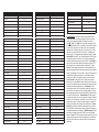
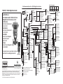
Menu Tree applies to:
Field Communicator Menu Tree - DVC2000 Digital Valve Controller
Instrument Level HC, AD, and PD
FIELDVUEt DVC2000 Digital Valve Controller
www.FIELDVUE.com
For the telephone number of the Emerson Process
Management sales office nearest you, contact:
In North America
Fisher Controls International LLC
1 (641) 754-3011
In Latin America
Fisher Controls International LLC
1 (314) 746-9900
In Asia Pacific
Emerson Process Management
Asia Pacific Private Ltd.
(65) 6777-8211
In Europe
Emerson Process Management Ltd.
+44 1634 895800
Hot Key
1 Instrument Mode
2 Protection
3 Tuning 3
1‐1
TM
For equipment service or support needs, contact your
local Emerson Process Managment sales office.
475 Field
Communicator
D103217X012 April 2010
Fisher and FIELDVUE are marks owned by one of the companies in the Emerson Process
Management business division of Emerson Electric Co. Emerson, Emerson Process
Management, and the Emerson logo are trademarks and service marks of Emerson Electric
Co. HART is a mark owned by the HART Communication Foundation. All other marks are
the property of their respective owners.
EFisher Controls International LLC 2010; All Rights Reserved
Setup & Diag
1 Basic Setup
2 Detailed Setup
3 Display
4 Calibrate
5 Stroke Valve
Online
1 Setup & Diag
2 Analog In
3 Travel
4 Travel SP
5 Drive Sgl
6 Pressure
7 Instrument Status
7
1
www.Fisher.com
Basic Setup
1 Auto Setup
2 Manual Setup
1‐2
1
1‐1‐1
1‐1‐2
Auto Setup
1 Setup Wizard
2 Auto Calib Travel
3 Auto Tuner
4 Tuning
Manual Setup
1 Instrument Mode
2 Press & Actuator
3 Tuning & Calib
Detailed Setup
1 Mode
2 Protection
3 General
4 Measured Var
5 Actuator & Valve
6 Response Control
7 Alerts
8 Self Test Shutdown
9 Transmitter/Switches
1‐3
Display
1 Variables
2 Device Information
3 DD Revision
1‐4
Calibrate
1 Analog In Calib
2 Auto Calib Travel
3 Manual Calib Travel
4 Pressure Calib
5 Auto Tuner
6 Transmitter Calib
Instrument Status 1‐5
1 Valve Alerts
2 Failure Alerts
3 Operational Status
4 Display Record
2
Stroke Valve
1 Done
2 Ramp Open
3 Ramp Closed
4 Ramp to Target
5 Step to Target
1‐2‐1
Tuning
1 Tuning Set
2 Damping Factor
3 Expert Tuning Gains
Mode
1 Instrument Mode
2 Control Mode
3 Restart Cont Mode
4 Restart
5 Burst
1‐1‐2‐3
1‐2‐3
1‐2‐4
2
1‐3‐1
1‐3‐2
Hardware
Revision
1
Variables
1 Temp
2 Cycle Count
3 Tvl Accum
1‐2‐9
Device Information
1 HART Univ Rev
2 Device Rev
3 Firmware Rev
4 Firmware Date
5 Main Elec Rev
6 Sec Elec Rev
7 Sensor Serial Num
8 Inst Level
9 Device ID
Self Test Shutdown
1 Flash Rom Fail
2 Temp Comp Fail
3 Ref Voltage Fail
4 Drive Current Fail
5 NVM Fail
6 Temp Sensor Fail
7 Press Sensor Fail
8 Travel Sensor Fail
Transmitters/Switches
1 Switch 1 Trip Point
2 Switch 1 Closed
3 Switch 2 Trip Point
4 Switch 2 Closed
5 Transmitter Action
Tuning & Calib
1 Tuning Set
1‐2‐1‐5
2 Damping Factor
3 Expert Tuning Gains 4
4 Tvl Cutoff Lo
5 Auto Calib Travel
General
1 HART Tag
2 Message
3 Descriptor
4 Date
5 Valve Serial Num
6 Inst Serial Num
7 Polling Address
8 LUI Language
1‐2‐7‐2
1‐2‐6‐7
1‐2‐6‐8
1‐2‐6‐9
1‐2‐7‐1
Travel Dev Alert
1 Tvl Dev Alert Enab
2 Tvl Dev Alert Pt
3 Tvl Dev Time
Expert Tuning Gains
1 Prop Gain
2 Vel Gain
3 MLFB Gain
Burst
1 Burst Enable
2 Burst Command
Limits & Cutoffs
1 Travel Limit Hi
2 Travel Limit Lo
3 Travel Cutoff Hi
4 Travel Cutoff Lo
Min Open/Close
1 Min Opening Time
2 Min Closing Time
Integral Settings
1 Enab Int Control
2 Integral Gain
3 Integral Dead Zone
Travel Alerts
1 Tvl Hi/Lo Enab
2 Tvl HH/LL Enab
3 Tvl Alert Hi Pt
4 Tvl Alert Lo Pt
5 Tvl Alert Hi Hi Pt
6 Tvl Alert Lo Lo Pt
7 Tvl Alrt DB
Travel Accum Alert
1 Tvl Accum Alrt Enab
2 Tvl Accum Alrt Pt
3 Tvl Accum DB
Cycle Count Alert
4 Tvl Accum
1 Cycl Cnt Alrt Enab
1‐2‐7‐4
2 Cycl Cnt Alrt Pt
3 Cycle Count DB
1‐2‐7‐5
Other Alerts
4 Cycle Count
1 Drive Alert Enab
Record Group Enable
Alert Record
1‐2‐7‐6‐4 1 Valve Group Enab
1‐2‐7‐6 1 Display Record
2 Failure Group Enab
2 Clear Record
3 Lim Switch Stat En
3 Inst Date & Time
4 Record Group Enab
1‐2‐7‐3
2
Firmware
DD
Revision Revision
1, 2, & 3
1
1‐1‐1‐4‐3
Measured Var
1 Analog In Units
Actuator & Valve
2 Input Range Hi
1‐2‐5 1 Max Supply Press
3 Input Range Lo
2 Actuator Style
4 Pressure Units
3 Valve Style
5 LUI Pressure Units Response Control
4 Zero Control Signal 6 Temp Units
1 Tuning Set
1‐2‐6
2 Damping Factor 4
3 Expert Tuning Gains
Alerts
1‐2‐7
4 Input Char
1 Travel Alerts
5 Custom Char Table
2 Travel Dev Alert
6 Setpt Filter Time
3 Travel Accum Alert
7 Limits & Cutoffs
4 Cycle Count Alert
8 Min Open/Close
5 Other Alerts
9 Integral Settings
6 Alert Record
1‐2‐8
Field Communicator
1 Offline
2 Online
3 Frequency Device
4 Utility
Notes:
1
This
menu is available by pressing the left
arrow key from the previous menu.
2
Available
only if the instrument has a transmitter
and limit switches installed.
3
See
menu 1‐1‐1‐4
4
See
menu 1‐1‐1‐4‐3
1‐1‐2‐2
1‐1‐1‐4
Press & Actuator
1 Pressure Units
2 LUI Pressure Units
3 Max Supply Press
4 Actuator Style
5 Valve Style
7 Zero Control Signal
Device
Revision
1
Function/Variable
Actuator Style
Alert Record
Alert Record Group Enable
Analog Input
Analog Input Calibration
Analog Input Range High
Analog Input Range Low
Analog Input Units
Auto Calibrate Travel
Auto Setup
Auto Tuner
Basic Setup
Burst
Calibrate
Control Mode
Custom Characteristic Table
Cycle Count and Alert
Descriptor
Device Description Revision
Device Identification
Device Revision
Drive Alert Enable
Drive Signal
Failure Alerts
Firmware Date
Firmware Revision
HARTR Tag
HART Universal Revision
Input Characterization
Instrument Level
Instrument Mode
Instrument Serial Number
Instrument Status
Integral Control Enable
Integral Dead Zone
Integral Gain
LUI Language
LUI Pressure Units
Fast‐Key Sequence
1‐1‐2‐2‐4 or 1‐2‐5‐2
1‐2‐7‐6
1‐2‐7‐6‐4
2
1‐4‐1
1‐2‐4‐2
1‐2‐4‐3
1‐2‐4‐1
1‐4‐2 or 1‐1‐2‐3‐5
1‐1‐1
1‐1‐1‐3
1‐1
1‐2‐1‐5
1‐4
1‐2‐1‐2
1‐2‐6‐5
1‐2‐7‐4
1‐2‐3‐3
1‐3‐3
1‐3‐2‐9
1‐3‐2‐2
1‐2‐7‐5‐1
5
7‐2
1‐3‐2‐4
1‐3‐2‐3
1‐2‐3‐1
1‐3‐2‐1
1‐2‐6‐4
1‐3‐2‐8
Hot Key
1‐2‐3‐6
7
1‐2‐6‐9‐1
1‐2‐6‐9‐3
1‐2‐6‐9‐2
1‐2‐3‐8
1‐2‐4‐5
Function/Variable
Main Electronics Revision
Manual Calibrate Travel
Manual Setup
Maximum Supply Pressure
Message
Minimum Closing Time
Minimum Opening Time
Operational Status
Polling Address
Pressure
Pressure Calibration
Pressure Units
Protection
Restart
Restart Control Mode
Secondary Electronics Revision
Self Test Shutdown
Sensor Serial Number
Set Point Filter Time
Setup Wizard
Stroke Valve
Switch 1 Closed(1)
Switch 1 Trip Point(1)
Switch 2 Closed(1)
Switch 2 Trip Point(1)
Temperature
Temperature Units
Transmitter Action(1)
Transmitter Calibration(1)
Travel
Travel Accumulator Alert
Travel Alerts
Travel Cutoff High
Travel Cutoff Low
Travel Deviation Alert
Travel Limit High
Travel Limit Low
Travel Setpoint
Fast‐Key Sequence
1‐3‐2‐5
1‐4‐3
1‐1‐2
1‐1‐2‐2‐3 or 1‐2‐5‐1
1‐2‐3‐2
1‐2‐6‐8‐2
1‐2‐6‐8‐1
7‐3
1‐2‐3‐7
6
1‐4‐4
1‐2‐4‐4
Hot Key
1‐2‐1‐4
1‐2‐1‐3
1‐3‐2‐6
1‐2‐8
1‐3‐2‐7
1‐2‐6‐6
1‐1‐1‐1
1‐5
1‐2‐9‐2
1‐2‐9‐1
1‐2‐9‐4
1‐2‐9‐3
1‐3‐1‐1
1‐2‐4‐6
1‐2‐9‐5
1‐4‐6
3
1‐2‐7‐3
1‐2‐7‐1
1‐2‐6‐7‐3
1‐2‐6‐7‐4
1‐2‐7‐2
1‐2‐6‐7‐1
1‐2‐6‐7‐2
4
Function/Variable
Tuning
Tuning Set
Fast‐Key Sequence
Hot Key
1‐1‐2‐3‐1 or 1‐1‐1‐4‐1 or 1‐2‐6‐1
Valve Serial Number
1‐2‐3‐5
Valve Style
1‐2‐5‐3
Zero Control Signal
1‐2‐5‐4
1. Available only if the instrument has a transmitter and limit switches installed.
Diagnostic Messages The DVC2000 is constantly diagnosing itself for abnormal
conditions while powered up. The following messages will appear on the local user
interface if a fault condition exists (identified on the default screen by the alert
symbol ! ). Switch 1 ??? / Switch 2 ???: The alert symbol in conjunction with this
text indicates that limit switch circuit 1 is not powered, or at least one switch is enabled.
In order for either of the switches to work, switch circuit 1 must be powered. Switch 2
cannot work alone. To eliminate the alert symbol, you can either apply 5 to 30 VDC to
switch circuit 1 or disable both switches. Once switch circuit 1 is powered properly,
question marks (???) will indicate that the corresponding switch is disabled. Device
Locked by HART: Another HARTt host is communicating with the DVC2000. Typically
this means the instrument is “out of service”. In fw3 or later, clear this message by
holding down the left button while cycling power to the DVC2000. Check Supply: The
valve is not able to reach its target position due to insufficient supply pressure. This
error will most likely occur in conjunction with the Travel Deviation error. Travel
Deviation: This error message indicates that there is a difference between the input
signal (after characterization) and the actuator travel reading from the position feedback
element. The default setting is 7% travel deviation for 5 seconds. These settings can be
configured through a HART communicating host on any HC instrument or higher.
Possible sources of this error are insufficient air supply or excessive valve friction.
Check I/P Converter: A problem relating to the I/P converter has been detected.
Sources of this error include: DElectronics problems indicated by the drive current read
back being out of range. DLow supply pressure indicated by an active drive signal alert,
and DA stuck valve resulting in integrator wind‐up. Check Mounting: The valve
position feedback reading is valid, but it is outside the operating range. Sources of this
error include loose or bent mounting brackets or a misaligned magnet array. This error
does not identify faulty components, but rather faulty installation or alignment. This alert
is also called a Travel Sensor Failure. Shutdown Activated: This screen appears if
the positioner has shut down and no air is being delivered to the actuator. This indicates
that the valve is at it's fail‐safe position. An example of a source of this error is corrupt
firmware code upon start‐up. The factory setting default for this error is disabled. This
alert will only be enabled by actively configuring it with a HART based host. Replace
Main Board: A problem with the electronics has been detected. Sources of this error
may include hardware or firmware problems. If this error is detected the instrument may
be operational but performance will be degraded. FIELDVUE Instruments: Displayed
when there are no languages loaded on the DVC2000. Could occur during firmware
download. Pressure = ???: The actuator pressure reading is greater than 125% of the
configure maximum supply pressure. Reduce the supply pressure or stroke that valve
closed (air‐to‐open/fail close setup), eventually there will be a point where numerical
values appear.