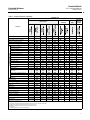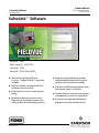
1
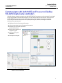
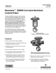
ValveLink Software
D102227X012
Product Bulletin
62.1:ValveLink Software
October 2012
ValveLinkt Software
ValveLinkt Solo
AMS ValveLinkt SNAP‐ONt
ValveLinkt DTM
ValveLinkt PLUG‐IN for PRMr
H Communicate with both HARTr and
FOUNDATIONt fieldbus FIELDVUEt digital valve
controllers
H Configure, calibrate, and diagnose FIELDVUE
instruments from one location
H Use the Performance Tuner to easily optimize
tuning
H Performance Diagnostics provide in‐service
diagnostics for monitoring the health of the
valve assembly without disturbing the process
www.Fisher.com
H Diagnostics provide validation of assembly
rebuild and detailed insight into the physical
condition of the valve/actuator assembly
H Setup and test FIELDVUE instruments for Safety
Instrumented System (SIS) Solutions
H Scheduler allows you to specify a time and date
to automatically run tasks on a regular basis
H Save time by preconfiguring calibration and
diagnostics in the shop with Batch Runner
Product Bulletin
ValveLink Software
62.1:ValveLink Software
October 2012
D102227X012
ValveLink Software Product Suite
ValveLink software is available in a variety of configurations to allow you to realize the full benefit of FIELDVUE digital
valve controllers.
ValveLink Solo
ValveLink Solo permits users to perform configuration, calibration, and
diagnostics on HART and FOUNDATION Fieldbus FIELDVUE digital valve controllers.
Integrate ValveLink software into AMS Suite: Intelligent Device Manager
AMS ValveLink SNAP‐ON provides integration with AMS Suite: Intelligent Device
Manager to perform configuration, calibration, and diagnostics. Integration with
AMS Device Manager provides the ability to communicate with FIELDVUE digital
valve controllers via DeltaVt, Ovationt, PROVOXt, HART multiplexers, and
HART modems. Non‐Emerson host integration, including Invensys and Honeywell
(HART only) systems, can be provided through HSI (Host System Integration).
Integrate ValveLink DTM into Field Device Tool - FDT
ValveLink DTM provides integration into a Field Device Tool frame application to
perform configuration, calibration, and diagnostics on FIELDVUE digital valve
controllers. The ValveLink DTM is certified with the FDT group.
Integrate AMS ValveLink Software into the Yokogawa Plant Resource
Manager (PRM)
ValveLink PLUG‐IN for PRM provides integration with the Yokogawa Plant
Resource Manager (PRM). This integration provides PRM users with the ability to
launch the ValveLink PLUG‐IN for PRM directly from PRM and to communicate
with HART and FOUNDATION fieldbus FIELDVUE digital valve controllers through
PRM and the Yokogawa CENTUM CS 3000 R3 and CENTRUM VP.
ValveLink software is a core component of the proven PlantWebt digital plant architecture. ValveLink
software powers PlantWeb through predictive and proactive control valve maintenance using
intelligent digital valve controllers to improve availability and performance.
2
ValveLink Software
D102227X012
Product Bulletin
62.1:ValveLink Software
October 2012
Communicate with both HART and FOUNDATION fieldbus
FIELDVUE digital valve controllers
ValveLink software remotely communicates with HART FIELDVUE instruments over the existing 4‐20 mA signal
wiring using the HART communication standard. The same software also can communicate with FOUNDATION
fieldbus FIELDVUE instruments over the fieldbus H1 segment. Information is presented in a consistent,
easy‐to‐interpret interface that provides the capability to configure, calibrate, and diagnose FIELDVUE
instruments from one location:
H Dashboard of critical instrument information
H A device connection view of all connected instruments
H Monitoring of instrument operational
parameters and alerts
H Review and comparison of
diagnostic graphs
H Instrument setup and
calibration
H Data import and export
TREND VALVE TRAVEL AND PRESSURE
3
Product Bulletin
62.1:ValveLink Software
October 2012
ValveLink Software
D102227X012
Use the Performance Tuner to easily optimize tuning
The Performance Tuner lets you easily adjust a FIELDVUE digital valve controller for optimum performance. When
mounting a FIELDVUE digital valve controller, to either a Fisher or a non‐Fisher valve, the Performance Tuner can
optimize valve performance for you.
Performance Diagnostics provide in‐service diagnostics for
monitoring the health of the valve assembly without
disturbing the process
Performance Diagnostics (PD) provides predictive in‐service diagnostics for monitoring the health of the valve
assembly and customized diagnostics for advanced troubleshooting. Performance Diagnostics continuously analyze
the valve assembly and passively gather data without disturbing or interrupting the control valve while it is in the
process.
PD may be used to help detect problems with air leakage, valve assembly friction and deadband, instrument air
quality, loose connections, supply pressure restriction, and valve assembly calibration. When a problem is identified,
the diagnostic provides a description and severity of the problem, a probable cause, and recommended action.
In‐service diagnostics for troubleshooting allow custom diagnostics to be set up to collect data at a high‐frequency
collection rate and present the data in a graphical format.
Performance Diagnostics tests are available upon user request or a pre‐selected daily, weekly,
monthly, or yearly schedule without user intervention
4
ValveLink Software
D102227X012
Product Bulletin
62.1:ValveLink Software
October 2012
Provide Real‐Time Notification of Current and Potential
Valve and Instrument Problems using Performance
Diagnostics
Performance Diagnostics
enables the use of
diagnostics while the valve is
in‐service and operating.
Tests can be performed to
identify problems with the
entire control valve
assembly, such as:
H Red/Yellow/Green condition
indicator - provides a quick
visual indication of the
following:
G the physical condition of
the FIELDVUE instrument
I/P and relay components
G instrument air supply pressure
and volume
G relay adjustment on double acting
piston actuators
G the total air received and used by
the instrument, and
G why a valve assembly is deviating
from the set point
H PD One Button is a sweep of the above tests.
When the sweep is complete, ValveLink software
will show any errors, possible causes, and
recommended actions to resolve the error(s).
H Friction and Deadband Trending
Performance Diagnostics are available upon user
request or may be scheduled to automatically run
on a daily, weekly, or monthly basis.
Performance Diagnostics provide on‐line/in‐service
predictive diagnostics to identify faults and list possible
causes and recommended corrective actions for each fault
5
Product Bulletin
ValveLink Software
62.1:ValveLink Software
October 2012
D102227X012
Provide validation of assembly rebuild and detailed insight
into the physical condition of the valve/actuator assembly
Performance Diagnostics vary the digital valve controller set point and plot valve operation to provide insight into the
dynamic performance of the valve/actuator assembly. Out‐of‐service diagnostics such as valve signature, dynamic
error band, and step response assist in the identification of emerging valve problems quickly and accurately.
Out‐of‐service diagnostics are optimally run as part of a plant shutdown.
The Valve Signature diagnostic is used to:
H Evaluate valve friction, deadband, and
shutoff capability.
H Calculate actuator spring rate and
bench set.
H Identify potential packing problems.
H Compare current condition to previous
baseline condition.
H Signature Analyzer enables rapid analysis of the Valve
Signature to more efficiently manage your plant assets. Based
on default or user defined settings, Signature Analyzer provides
pass/fail results for Maximum Friction, Minimum Friction,
Stem Integrity, and Stick Slip, enabling better documentation
for required maintenance or validation of valve repairs.
Zoom in to examine valve
movement and other details
/
RESULT
BOUNDARY RESULTS
Diagnostic tests, such as the Valve Signature Diagnostic
example shown here, help you detect emerging valve
repair requirements before they impact performance
NEW
TEST
ORIGINAL
TEST
Signature Analyzer Boundary Editor allows you to use
default or customized test criteria
The Dynamic Error Band diagnostic is used to
analyze hysteresis, deadband, and dynamic error.
6
ValveLink software enables simultaneous
multiple overlay of tests (up to ten). This
allows you to trend valve history.
ValveLink Software
D102227X012
Product Bulletin
62.1:ValveLink Software
October 2012
The Step Response diagnostic allows you to evaluate how well the valve tracks an input change. By minimizing dead
time, deadband, and overshoot, process control is greatly enhanced. With the Step Response test you can:
H Validate tuning parameters.
H Obtain a numerical analysis for overshoot,
hysteresis, dead time, t63, and t86.
H Define up to 30 steps.
A performance step test provides a predefined
sequence of 25 steps. This test allows the user to
quickly evaluate valve and actuator response to
signal change and determine maximum
deadband.
Use the step response test to verify instrument
tuning and valve response to signal changes
Setup and test FIELDVUE instruments for Safety
Instrumented System (SIS) Solutions
Use ValveLink software to set up and test
the final control element in safety instrumented
system applications. ValveLink software for
DVC6000 SIS digital valve controllers provides:
H A Setup Wizard to set up the digital valve
controller for use in a Safety Instrumented
System. ValveLink software provides a
pneumatic hookup representation to help
ensure tubing is correctly connected.
H The capability to initiate a partial stroke test
of the final control element without requiring a
process shutdown. You can run a partial stroke
test to prove the valve will respond on demand.
Store partial stroke test results for future comparison
and study. You can also initiate the test by shorting
the AUX Terminal in the field with a push button
located at the device, or remotely from the valve.
At the same time the instrument performs the partial
stroke test, ValveLink software also gathers diagnostic
data. Use this data to evaluate valve performance and
determine if maintenance is required.
(Setup and test FIELDVUE instruments for Safety
Instrumented System (SIS) Solutions continued on next page)
7
Product Bulletin
62.1:ValveLink Software
October 2012
ValveLink Software
D102227X012
H A Signature Analyzer to automate diagnostics results
of Valve Signature and Partial Stroke diagnostic data.
The Signature Analyzer uses a set of user configurable
limits to help determine possible issues with the valve
assembly, such as a broken shaft or stem.
H A Trigger event that allows you to log the “Safety
Demand” event while storing pre‐event and post‐event
data. Trip event data can be accessed for an audit and
presented to regulatory or insurance authorities.
The Trigger functionality allows data to be collected and
stored in the microprocessor memory of the digital valve
controller. Trip event data can be accessed for an audit
and presented to a regulatory or insurance authority. The
trigger will initiate on‐board data collection based on a
change in actuator pressure, valve travel, input current,
pressure differential, travel deviation, or travel cutoff.
The data is stored on board the device for later retrieval,
and is retained in the event of a power loss.
A Trigger event, based on one of eight process
variables, documents a “Safety Demand” event
when used in a safety instrumented system
Every event performed with ValveLink software is
logged with a time and date stamp to document that
tests were run and how the valve assembly responded.
H Diagnostic information to allow predictive maintenance of the final control element. No need to unnecessarily
shutdown the process to perform maintenance on the safety shutdown valve.
H The capability to monitor the health of a solenoid valve downstream of the digital valve controller. This can improve
safety reliability and provide assurance that the solenoid valve is not stuck in the open position.
H ValveLink Solo Event Messenger capability
to send notification via email, pager, or cell phone
if a specific alert, or set of alerts, occurs on
a predefined set of safety shutdown valves.
8
ValveLink Software
D102227X012
Product Bulletin
62.1:ValveLink Software
October 2012
Scheduler allows you to specify a time and date to
automatically run tasks on a regular basis
With Scheduler, you can schedule tasks, such as in‐service Performance Diagnostics and SIS Partial Stroke
diagnostics to run on a recurring daily, weekly, monthly, or yearly schedule that you specify. A summary of the
outcome of scheduled tasks is available from within Scheduler and for complete details you can view the resulting
diagnostic graphs and analyses.
Save time by preconfiguring calibration and diagnostics in
the shop with Batch Runner
With Batch Runner you can setup
ValveLink software to automatically run
diagnostic tests, calibrate, or upload
configuration data from multiple valves
with a user specified routine. During a
turnaround or production change, you
can download firmware, upload
configurations, run the Performance
Tuner to optimize tuning, or even reset
the instrument clock without any
interaction by personnel.
Batch Runner increases efficiency by
allowing you to set up a batch once, and
repeatedly run that set of actions on
different groups of valve assemblies.
Use Batch Runner to automate diagnostic tests and other repetitive activities
9
Product Bulletin
62.1:ValveLink Software
October 2012
ValveLink Software
D102227X012
Specifications(1)
Available Configurations
See table 1
Recommended Minimum Hardware Requirements
800 MHz processor (WindowsR XP and Windows
ServerR 2003), or
1 GHz processor (Windows VistaR, Windows 7,
and Windows Server 2008)
256 MB RAM (Windows XP and Windows Server
2003, or
1 GB RAM (Windows Vista, Windows 7, and
Windows Server 2008)
Video: 1024x768, 256 color VGA
CD‐ROM drive
USB Port
Optional Hardware
HART Modem(2)
Standard RS‐232, requires a dedicated interrupt
MACTekR VIATORR USB HART Modem, requires
a USB port
MACTek VIATOR BluetoothR HART Interface,
requires Windows Bluetooth Serial Port
Profile (SPP)
ProComSol Bluetooth HART Interface, requires
Windows Bluetooth SPP
HART Multiplexer
Standard RS‐232 port, requires RS‐485 converter
Fieldbus H1 (NI)
NI PCMCIA‐FBUS Series 2
NI PCMCIA‐FBUS/2 Series 2
NI PCI‐FBUS/2
NI USB‐8486
1. Specifications do not apply to AMS ValveLink SNAP‐ON.
2. ValveLink Solo 64 bit HART modem not supported.
3. ValveLink software is not supported on Windows NT, Windows 95, Windows ME, or Windows 2000.
10
Supported Operating Systems(3)
ValveLink Solo
Windows XP (32 bit)
Windows Vista (32 bit)
Windows 7 operating systems (32/64 bit)
Windows Server 2003 (32 bit)
Windows Server 2008 (32/64 bit)
AMS ValveLink SNAP‐ON
Operating Systems supported by AMS Suite:
Intelligent Device Manager v8.0, v9.0, v10.1,
v10.5.1, v11.0, v11.1.1, v11.5 and newer
ValveLink DTM
FDT frame applications using:
Window XP (32 bit)
Windows Vista (32 bit)
Windows 7 operating systems (32/64 bit)
Windows Server 2003 (32 bit)
Windows Server 2008 (32/64 bit)
ValveLink PLUG‐IN for PRM
Operating Systems supported by Yokogawa Plant
Resource Manager (PRM) v3.02 and newer
Modbus Interface
Modbus Protocol:
RTU or ASCII
Function codes 1, 2, 3, 4, and 8 (subfunction 0)
Slave address 1 to 255 (user selectable)
Communication Rate: 300 to 19.2 kbaud
Data Types:
Function codes 1 & 2—Alert Status
Function Codes 3 & 4—Analog Values
IEEE double precision floating point
Signed integer
Scaled integer
Electrical Connection to Control System:
RS‐232 or RS‐485
Product Bulletin
ValveLink Software
62.1:ValveLink Software
October 2012
D102227X012
Table 1. ValveLink Software Capability
PRODUCT TYPE
AMS ValveLink
SNAP‐ON
ValveLink Solo
ValveLink
DTM
ValveLink
PLUG‐IN
for PRM
CAPABILITY
F
HART Modem
F
F
F
HART Multiplexer
F
F(1)
F(1)
F
F(1)
F(1)
F(1)
F(1)
WirelessHARTr Communications
FOUNDATION Fieldbus PC Card
F
F
F
F
FOUNDATION USB Interface
F
F
F
F
Valve Signature(2)
f
F
f
F
F
F
F
F
F
Dynamic Error Band(2)
f
F
f
F
F
F
F
F
F
Drive Signal Test(2)
f
F
f
F
F
F
F
F
F
Step Response(2)
f
F
f
F
F
F
F
F
F
Step Response Analysis
f
F
f
F
F
f
F
F
F
Performance Step Test(2)
f
f
f
F
F
f
F
F
F
Graph Overlay
f
F
F
F
F
F
F
F
F
F
F
F
F
Stroke Valve
I/P & Relay Integrity
f
F
F
F
F
F
F
F
F
Travel Deviation
f
F
F
F
F
F
F
F
F
Supply Pressure(3)
f
F
F
F
F
F
F
F
F
Relay Adjustment(3)
f
F
F
F
F
F
F
F
F
Air Mass Flow(3)
f
F
F
F
F
F
F
F
F
PD One Button
f
F
F
F
F
F
F
F
F
Valve Friction / Deadband
Estimation
Valve Friction / Deadband Trend
f
F
F
F
F
F
F
F
F
f
F
F
F
F
F
F
F
F
Profiler
f
F
F
F
F
F
F
F
F
Triggered Profile
f
F
F
F
F
F
F
F
F
f
F
F
F
F
F
F
F
F
F
F
F
F
Status Monitor
Network Scan(4)
F
F
F
F
Event Messenger(4)
f
F
F
F
F
Modbus(4)
F
F
F
F
F
F
F
F
F
F(5)
F
F
F
F
F
F
F
F(5)
F
F
F
F
F
F
F
Firmware Download(3)
F
F
F
F
F
F
F
F
Temporary Tiering(3)
F
F
F
F
F
F
F
F
Instrument Level StepUp
F
F
F
F
F
F
F
F
Trending(4)
Batch Runner
Scheduler
F
DataSync
Initial Tag Limit
Unlimited
5
125
125
32 or 125
25
100
Unlimited
Unlimited
Max Tag Limit
Unlimited
75
Unlimited
Unlimited
Unlimited
---(1)
---(1)
Unlimited
Unlimited
F Indicates capability available
f Indicates diagnostics can be reviewed but not run
1. AMS based capability. AMS ValveLink SNAP‐ON does not control or limit this functionality.
2. Diagnostic can only be run when the instrument is out of service.
3. DVC6200, DVC6200f, DVC6000, DVC6000f, and DVC2000 only.
4. HART only.
5. Limited to Host DDT Frame connected devices.
11
Product Bulletin
62.1:ValveLink Software
October 2012
ValveLink Software
D102227X012
Neither Emerson, Emerson Process Management, nor any of their affiliated entities assumes responsibility for the selection, use or maintenance
of any product. Responsibility for proper selection, use, and maintenance of any product remains solely with the purchaser and end user.
Fisher, FIELDVUE, ValveLink, SNAP-ON, DeltaV, Ovation, PROVOX, and PlantWeb are marks owned by one of the companies in the Emerson Process
Management business unit of Emerson Electric Co. Emerson Process Management, Emerson, and the Emerson logo are trademarks and service marks of
Emerson Electric Co. HART and WirelessHART are marks owned by the HART Communication Foundation. FOUNDATION is a mark owned by the Fieldbus
Foundation. Windows, Windows Server, and Windows Vista are registered trademarks of Microsoft Corporation in the United States and other countries. All
other marks are the property of their respective owners.
The contents of this publication are presented for informational purposes only, and while every effort has been made to ensure their accuracy, they are not
to be construed as warranties or guarantees, express or implied, regarding the products or services described herein or their use or applicability. All sales are
governed by our terms and conditions, which are available upon request. We reserve the right to modify or improve the designs or specifications of such
products at any time without notice.
Emerson Process Management
Marshalltown, Iowa 50158 USA
Sorocaba, 18087 Brazil
Chatham, Kent ME4 4QZ UK
Dubai, United Arab Emirates
Singapore 128461 Singapore
www.Fisher.com
E
121995, 2012 Fisher Controls International LLC. All rights reserved.