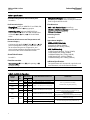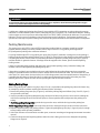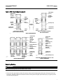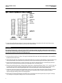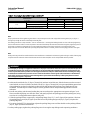
1
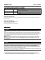
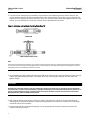
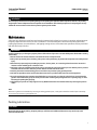
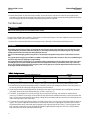
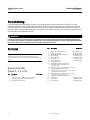
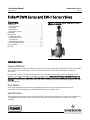
Instruction Manual EWN and EW-1 Valves D100400X012 July 2014 Fisherr EWN Series and EW-1 Series Valves Contents Introduction . . . . . . . . . . . . . . . . . . . . . . . . . . . . . . . . . 1 Scope of Manual . . . . . . . . . . . . . . . . . . . . . . . . . . . . . 1 Description . . . . . . . . . . . . . . . . . . . . . . . . . . . . . . . . . 1 Specifications . . . . . . . . . . . . . . . . . . . . . . . . . . . . . . . 1 Educational Services . . . . . . . . . . . . . . . . . . . . . . . . . 3 Installation . . . . . . . . . . . . . . . . . . . . . . . . . . . . . . . . . . 3 Maintenance . . . . . . . . . . . . . . . . . . . . . . . . . . . . . . . . . 5 Packing Lubrication . . . . . . . . . . . . . . . . . . . . . . . . . . 5 Packing Maintenance . . . . . . . . . . . . . . . . . . . . . . . . . 6 Trim Removal . . . . . . . . . . . . . . . . . . . . . . . . . . . . . . 10 Lapping Seating Surfaces . . . . . . . . . . . . . . . . . . . . 11 Valve Plug Maintenance . . . . . . . . . . . . . . . . . . . . . 12 Parts Ordering . . . . . . . . . . . . . . . . . . . . . . . . . . . . . . . 14 Parts List . . . . . . . . . . . . . . . . . . . . . . . . . . . . . . . . . . . 14 Figure 1. Fisher EWNT-2 NPS 12 x 8 EWNT-2 Valve with Typical Actuator W3310 Introduction Scope of Manual This instruction manual includes installation, maintenance, and parts information for Fisher NPS 8 x 6 and 12 x 8 EWN Series and EW-1 Series valves (figure 1). Refer to separate manuals for instructions covering the actuator and accessories. Do not install, operate, or maintain an EWN or EW-1 Series valve without being fully trained and qualified in valve, actuator, and accessory installation, operation, and maintenance. To avoid personal injury or property damage, it is important to carefully read, understand, and follow all the contents of this manual, including all safety cautions and warnings. If you have any questions about these instructions, contact your Emerson Process Management sales office before proceeding. Description These single-port globe-style valves have cage guiding, threaded seat rings, metal-to-metal seating, and push-down-to-close valve plug action. Additional details are given in tables 1 and 2. Specifications Typical specifications for these valves are shown in table 1. Some of the specifications for a given valve assembly as it was shipped from the factory appear on the actuator nameplate if the valve is part of a complete control valve assembly. www.Fisher.com Instruction Manual EWN and EW-1 Valves D100400X012 July 2014 Table 1. Specifications Available Configurations and Valve Body Sizes See table 2 End Connection Styles Whisper Trim™ Cages: Linear, except equal percentage for first 38.1 mm (1.5 inch) of travel with level D cage for NPS 8 x 6 valve Flow Directions Flanged Ends: Styles per ASME B16.5 are CL300, 600, or 900 J raised-face or J ring-type joint EWS-1 with Standard Cage: Normally up All Others with Standard Cages: Normally down Buttwelding Ends: Styles per ASME B16.25 are Schedule J 40 or J 80 for all CL300 and 600 valves or Schedule J 80, J 100, or J 120 for all CL900 valves Whisper Trim Cages: Always up Maximum Inlet Pressures and Temperatures and Pressure Drops(1) Consistent with applicable J CL300, J 600, or J 900 pressure/temperature ratings per ASME B16.34, but do not exceed the pressure, temperature, and pressure drop conditions specified when the valve was ordered. Also see the Installation section Shutoff Classifications See table 3 Flow Characteristics Standard Cages: J Linear, J quick-opening, or J equal percentage Valve Plug Travels See table 2 Approximate Weights NPS 8 x 6 CL900 Valve Body Flanged Ends: 839 kg (1850 lb) Buttwelding Ends: 703 kg (1550 lb) NPS 12 x 8 Valve Body CL300 (Flanged Ends Only): 721 kg (1590 lb) CL600 Flanged Ends: 930 kg (2050 lb) CL600 Buttwelding Ends: 726 kg (1600 lb) CL900 Flanged Ends: 1497 kg (3300 lb) CL900 Buttwelding Ends: 1293 kg (2850 lb) Additional Specifications For specifications such as materials, cage levels, and stem diameters, refer to the Parts List section. 1. The pressure or temperature limits in this manual and any applicable standard limitations should not be exceeded. Table 2. Available Configurations PRESSURE RATING VALVE SIZE, NPS CL900 12 x 8 CL900 CL300, 600, or 900 VALVE BODY DESIGN & CAGE STYLE 76 3 EWD-1 with standard cage 152 6 EWD-1 with Whisper Trim III cage 8x6 127 5 12 x 8 203 8 EWND-1 with Whisper Trim III cage only 8x6 127 5 12 x 8 203 8 CL300, 600, or 900 12 x 8 203 8 EWNT-2 with Whisper Trim III cage only 76 3 EWS-1 with standard cage only CL900 12 x 8 76 3 EWT-1 with standard cage 152 6 EWT-1 with Whisper Trim III cage CL900 2 VALVE PLUG TRAVEL mm Inches EWNT-1 with Whisper Trim III cage only DESCRIPTION Seat ring threaded to valve body; balanced valve plug with piston ring Seat ring threaded to valve body; balanced valve plug with spring-loaded seat ring Seat ring threaded to cage; balanced valve plug; spring-loaded seal rings on both seat ring and valve plug Seat ring threaded to valve body; unbalanced valve plug Seat ring threaded to valve body; balanced valve plug with spring-loaded seal ring Instruction Manual EWN and EW-1 Valves D100400X012 July 2014 Table 3. Shutoff Classification Per ANSI/FCI 70-2 and IEC 60534-4 Valve Seating Shutoff Class EWD-1 or EWND-1 Metal EWND-1 Metal IV (optional with extra piston rings) EWS-1 Metal IV (standard) EWNT-1, EWNT-2, or EWT-1 Metal II (standard) III (optional for CL300 or CL600 valves only) V (optional, consult your Emerson Process Management sales office) IV (standard) Educational Services For information on available courses for the Fisher EWN series and EW-1 series valves, as well as a variety of other products, contact: Emerson Process Management Educational Services - Registration Phone: 1-641-754-3771 or 1-800-338-8158 E-mail: [email protected] http://www.emersonprocess.com/education Installation WARNING Always wear protective gloves, clothing, and eyewear when performing any installation operations to avoid personal injury. Personal injury or equipment damage caused by sudden release of pressure may result if the valve assembly is installed where service conditions could exceed the limits given in table 1 or on the appropriate nameplates. To avoid such injury or damage, provide a suitable overpressure protection device as required by local, state, and Federal codes and good engineering practices. Check with your process or safety engineer for any additional measures that must be taken to protect against process media. If installing into an existing application, also refer to the WARNING at the beginning of the Maintenance section in this instruction manual. CAUTION When ordered, the valve configuration and construction materials were selected to meet particular pressure, temperature, pressure drop, and controlled fluid conditions. Responsibility for the safety of process media and compatibility of valve materials with process media rests solely with the purchaser and end-user. Since some valve body/trim material combinations are limited in their pressure drop and temperature ranges, do not apply any other conditions to the valve without first contacting your Emerson Process Management sales office. If hoisting the valve, the use of a nylon sling is recommended to protect the painted surfaces. Also be careful to position the sling so there will be no damage to the tubing or any accessories. 1. Before installing the valve, inspect the valve body and associated equipment for any damage and any foreign material. Make certain that the valve body interior is clean, pipelines are free of foreign material, and the valve is oriented so that pipeline flow is in the same direction as the arrow on the side of the valve body. 3 Instruction Manual EWN and EW-1 Valves D100400X012 July 2014 2. The control valve assembly may be installed in any orientation unless limited by seismic criteria. However, the normal method is with the actuator vertical above the valve. Other positions may result in uneven valve plug and cage wear and in improper operation. With some valves, the actuator may also need to be supported when it is not vertical. For more information, consult your Emerson Process Management sales office. Figure 2. Lubricator and Lubricator/Isolating Valve (Key 14) LUBRICATOR 10A9421-A AJ5428-D A0832-1 LUBRICATOR/ISOLATING VALVE Note If the valve being installed has a Whisper Trim cage with small internal flow passages, consideration should be given to installing an upstream strainer to prevent the lodging of particles in these passages. This is especially important if the pipeline cannot be thoroughly cleaned or if the flowing medium is not clean. 3. Use accepted piping and welding practices when installing the valve in the line. Internal elastomeric parts may stay in place during the welding procedure. For flanged valves, use a suitable gasket between the valve body and pipeline flanges. CAUTION Depending on valve body materials used, post weld heat treating may be required. If so, damage to internal elastomeric and plastic parts, as well as internal metal parts is possible. Shrunk-fit pieces and threaded connections may also loosen. In general, if post weld heat treating is to be performed, all trim parts should be removed. Contact your Emerson Process Management sales office for additional information. 4. With a leak-off bonnet construction, remove the 1/4 NPT pipe plugs (keys 14 and 16, figure 6) to hook up the leak-off piping. If continuous operation is required during inspection or maintenance, install a three-valve bypass around the control valve assembly. 5. If the actuator and valve are shipped separately, refer to the appropriate actuator instruction manual for the actuator mounting procedure. 4 Instruction Manual EWN and EW-1 Valves D100400X012 July 2014 WARNING Personal injury could result from packing leakage. Valve packing was tightened before shipment; however, the packing might require some readjustment to meet specific service conditions. Check with your process or safety engineer for any additional measures that must be taken to protect against process media. Maintenance Valve parts are subject to normal wear and must be inspected and replaced as necessary. Inspection and maintenance frequency depends on the severity of service conditions. This section includes instructions for packing lubrication, packing replacement, trim maintenance, and lapping seating surfaces. All maintenance operations may be performed with the valve body in the line. WARNING Avoid personal injury or damage to property from sudden release of pressure or uncontrolled process fluid. Before starting disassembly: D Do not remove the actuator from the valve while the valve is still pressurized. D Always wear protective gloves, clothing, and eyewear when performing any maintenance operations to avoid personal injury. D Disconnect any operating lines providing air pressure, electric power, or a control signal to the actuator. Be sure the actuator cannot suddenly open or close the valve. D Use bypass valves or completely shut off the process to isolate the valve from process pressure. Relieve process pressure from both sides of the valve. Drain the process media from both sides of the valve. D Vent the pneumatic actuator loading pressure and relieve any actuator spring precompression. D Use lock-out procedures to be sure that the above measures stay in effect while you work on the equipment. D The valve packing box may contain process fluids that are pressurized, even when the valve has been removed from the pipeline. Process fluids may spray out under pressure when removing the packing hardware or packing rings, or when loosening the packing box pipe plug. D Check with your process or safety engineer for any additional measures that must be taken to protect against process media. Note Whenever a gasket seal is disturbed by removing or shifting gasketed parts, a new gasket should be installed upon reassembly. This is necessary to ensure a good gasket seal. Packing Lubrication CAUTION Do not lubricate graphite packing. Graphite packing is self-lubricated. Additional lubrication may result in slip-stick movement of the valve. 5 EWN and EW-1 Valves July 2014 Instruction Manual D100400X012 WARNING To avoid personal injury or property damage resulting from fire or explosion, do not lubricate packing used in oxygen service or in processes with temperatures over 260_C (500_F). If a lubricator or lubricator/isolating valve (figure 2) is provided for PTFE/composition or other packings that require lubrication, it will be installed in place of the 1/4 NPT pipe plug (key 14, figure 6). Use a silicon-base lubricant. Packing used in oxygen service or in processes with temperatures over 260C (500F) should not be lubricated. To operate the lubricator, turn the cap screw clockwise to force the lubricant into the packing box. The lubricator/isolating valve operates the same way except the isolating valve must first be opened and then closed after lubrication is completed. Packing Maintenance This section covers only PTFE V-ring and PTFE/composition packing. Refer to a separate manual for graphite laminate/filament packing if used. Key numbers refer to figure 3 for PTFE V-ring packing and to figure 4 for PTFE/composition packing unless otherwise indicated. For spring-loaded single PTFE V-ring packing, the spring (key 8, figure 3) maintains a sealing force on the packing. If leakage is noted around the packing follower (key 13, figure 3), check to be sure the shoulder on the packing follower is touching the bonnet. If the shoulder is not touching the bonnet, tighten the packing flange nuts (key 5, figure 6) until the shoulder is against the bonnet. If leakage cannot be stopped in this manner, proceed to the Replacing Packing section. If there is undesirable packing leakage with other than spring-loaded packing, first try to limit the leakage and establish a stem seal by tightening the packing flange nuts. If the packing is relatively new and tight on the stem and if tightening the packing flange nuts does not stop the leakage, it is possible that the valve stem is worn or nicked so that a seal cannot be made. The surface finish of a new valve stem is 0.1 micro-meter (4 micro-inches) rms. If the leakage comes from the outside diameter of the packing, it is possible that the leakage is caused by nicks or scratches around the packing box wall. If performing any of the following procedures, inspect the valve stem and packing box wall for nicks and scratches. Adding Packing Rings When using packing with a lantern ring (key 8, figure 3 or 4), it is possible to add packing rings above the lantern ring as a temporary measure without removing the actuator from the valve body. 1. Remove the packing flange nuts (key 5, figure 6), and lift the packing flange and follower (keys 3 and 13, figure 6) away from the valve body. 2. It may be possible to dig out the old packing rings on top of the lantern ring, but use care to avoid scratching the valve stem or packing box wall. Clean all metal parts to remove particles that would prevent the packing from sealing. 3. If split-ring packing is being added, spread the rings over the stem, and slide the rings into the packing box. If solid-ring packing is being added, remove the stem connector, and slip the rings over the end of the valve stem. 4. Replace the packing flange and packing follower. Tighten the packing flange nuts (key 5, figure 6) only far enough to stop leakage under operating conditions. 5. If the valve-actuator stem connection was taken apart, reconnect according to the appropriate actuator instruction manual. 6. Check for leakage around the packing follower when the valve is being put into service. Retighten the packing flange nuts as required. 6 Instruction Manual EWN and EW-1 Valves D100400X012 July 2014 Figure 3. PTFE V-Ring Packing Arrangements UPPER WIPER (KEY 12) UPPER WIPER (KEY 12) PACKING FOLLOWER (KEY 13) PACKING FOLLOWER (KEY 13) FEMALE ADAPTOR PACKING RING FEMALE ADAPTOR PACKING RING MALE ADAPTOR WASHER (KEY 10) SPRING (KEY 8) PACKING SET (KEY 6) MALE ADAPTOR PACKING BOX RING (KEY 11) PACKING BOX RING (KEY 11) FOR 316 OR 17-4PH SST METAL PACKING BOX PARTS LOWER WIPER LOWER WIPER B1429 FOR ALL OTHER METAL PACKING BOX PART MATERIALS SINGLE ARRANGEMENT UPPER WIPER (KEY 12) UPPER WIPER (KEY 12) PACKING FOLLOWER (KEY 13) MALE ADAPTOR (KEY 31) PACKING RING (KEY 7) FEMALE ADAPTOR (KEY 32) LANTERN RING (KEY 8) ASSEMBLY 1 (POSITIVE PRESSURES) ASSEMBLY 2 (VACUUM) ASSEMBLY 3 (POSITIVE PRESSURES & VACUUM) LOWER WIPER (KEY 30) DOUBLE ARRANGEMENT PACKING FOLLOWER (KEY 13) FEMALE ADAPTOR (KEY 32) PACKING RING (KEY 7) MALE ADAPTOR (KEY 31) LANTERN RING (KEY 8) PACKING BOX RING (KEY 11) PACKING BOX RING (KEY 11) 12A7839-A B1428 SPACER (KEY 8) 12A8178-A A2628 LOWER WIPER (KEY 30) LEAK-OFF ARRANGEMENT FOR 19.1 mm (3/4 IN.) STEM ONLY Replacing Packing WARNING Observe the warning at the start of the Maintenance section. 1. Disconnect the operating lines from the actuator and any leak-off piping from the bonnet. Disconnect the stem connector, and then remove the actuator from the valve by unscrewing the yoke locknut (key 15, figure 6) or the hex nuts (key 26, figure 6). 7 Instruction Manual EWN and EW-1 Valves D100400X012 July 2014 Figure 4. Detail of PTFE/Composition Packing Arrangements UPPER WIPER (KEY 12) PACKING FOLLOWER (KEY 13) PACKING RING (KEY 7) LANTERN RING (KEY 8) PACKING BOX RING (KEY 11) 12A8173-A A2619 12A8180-A A1498-2 TYPICAL (DOUBLE) ARRANGEMENT 12A8165-A 19.1 OR 25.4 mm (3/4 OR 1 IN.) STEMS 31.8 mm (1-1/4 IN.) STEMS LEAK-OFF ARRANGEMENT 2. Loosen the packing flange nuts (key 5, figure 6) so that the packing is not tight on the valve stem. Remove any travel indicator parts and stem locknuts from the valve stem threads. CAUTION When lifting the bonnet (key 1, figure 6), be sure that the valve plug and stem assembly remains in the valve and on the seat. This will avoid damage to the seating surfaces as a result of the assembly dropping from the bonnet after being lifted part way out. The parts are also easier to handle separately. 3. Unscrew the hex nuts (key 16, figure 7 through 10) that bolt the bonnet and valve body together, and carefully lift the bonnet off the valve stem. 4. If the valve plug and stem assembly starts to lift with the bonnet, use a brass or lead hammer on the end of the stem and tap it back down. Set the bonnet on a protective surface to prevent damage to the bonnet gasket surface. 5. Remove the bonnet gasket (key 10, figure 7 through 10), and cover the opening in the valve body to protect the gasket surface and prevent foreign material from getting into the valve body cavity. 6. Remove the packing flange nuts, packing flange, upper wiper, and packing follower (keys 5, 3, 12, and 13, figure 6). Carefully push out all the remaining packing parts from the valve body side of the bonnet using a rounded rod or other tool that will not scratch the packing box wall. Clean the packing box and the metal packing parts. 7. Inspect the valve stem threads and packing box surfaces for any sharp edges that might cut the packing. Scratches or burrs could cause packing box leakage or damage to the new packing. If the surface condition cannot be improved by light sanding, replace the damaged parts. 8. Remove the covering protecting the valve body cavity, and install a new bonnet gasket (key 10, figure 7 through 10), making sure the gasket seating surfaces are clean and smooth. 8 Instruction Manual EWN and EW-1 Valves D100400X012 July 2014 Table 4. Valve Body-to-Bonnet Bolt Torque Guidelines(1) BOLT TORQUES(2) FOR FIELD-LUBRICATED BOLTING VALVE SIZE, NPS 8 x 6 CL900 12 x 8 NSm LbfSFt 542 400 CL300 or 600 691 510 CL900 with steel or alloy steel bolting 2440 1800 CL900 with stainless steel bolting 2712 2000 1. For other materials, contact your Emerson Process Management sales office for torques. 2. Determined from laboratory tests. Note Proper performance of the tightening procedures in step 9 compresses the outer edge of the bonnet gasket (key 10, figure 7 through 10) enough to seal the valve body-to-bonnet joint. The bolting procedures in step 9 include -- but are not limited to -- ensuring that bolting threads are clean and evenly tightening the hex nuts onto the studs in a crisscross pattern. Because of the boltup characteristics of the bonnet gasket, tightening one nut may loosen an adjacent nut. Repeat the crisscross tightening pattern several times until each nut is tight and the valve body-to-bonnet seal is made. When the operating temperature has been reached, perform this torquing procedure once again. Note Stud(s) and nut(s) should be installed such that the manufacturer's trademark and material grade marking is visible, allowing easy comparison to the materials selected and documented in the Emerson/Fisher serial card provided with this product. WARNING Personal injury or damage to equipment could occur if improper stud and nut materials or parts are used. Do not operate or assemble this product with stud(s) and nut(s) that are not approved by Emerson/Fisher engineering and/or listed on the serial card provided with this product. Use of unapproved materials and parts could lead to stresses exceeding the design or code limits intended for this particular service. Install studs with the material grade and manufacturer's identification mark visible. Contact your Emerson Process Management representative immediately if a discrepancy between actual parts and approved parts is suspected. 9. Lubricate the stud bolts (key 15, figure 7 through 10) with anti-seize lubricant, slide the bonnet over the stem and onto the bolts, and secure with the stud bolt nuts (key 16, figure 7 through 10), using accepted bolting procedures during tightening so that the valve body-to-bonnet joint will withstand test pressures and application service conditions. The bolt torques in table 4 may be used as guidelines unless accepted bolting procedures dictate otherwise. 10. Install new packing and the metal packing box parts according to the appropriate arrangement in figure 3 or 4. Place a smooth-edged pipe over the valve stem, and gently tap each soft packing part into the packing box, being sure that air is not trapped between adjacent soft parts. 11. Slide the packing follower, upper wiper, and packing flange (keys 13, 12, and 3, figure 6) into position. Lubricate the packing flange studs (key 4, figure 6) and the faces of the packing flange nuts (key 5, figure 6). Replace the packing flange nuts. 12. For spring-loaded PTFE V-ring packing, tighten the packing flange nuts until the shoulder on the packing follower (key 13, figure 6) contacts the bonnet. For other packing types, tighten the packing flange nuts far enough to stop leakage under operating conditions. 9 Instruction Manual EWN and EW-1 Valves D100400X012 July 2014 13. Mount the actuator on the valve body assembly, and reconnect the actuator and valve stem according to the procedure in the appropriate actuator instruction manual. Check for leakage around the packing follower when the valve is being put into service. Retighten the packing flange nuts as required. Trim Removal WARNING Observe the warning at the start of the Maintenance section. Except where indicated, key numbers in this section are referenced in figures 7 and 8 for EWN Series constructions and in figures 9 and 10 for EW-1 Series constructions. 1. Remove the actuator and the bonnet according to steps 1 through 5 of the Replacing Packing section. CAUTION When lifting the valve plug stem (key 7) and attached valve plug (key 2) out of the valve body, be certain that the cage or cage assembly (key 3) remains in the valve body (key 1). This is to prevent damage caused by the cage or cage assembly dropping back into the valve body after being lifted part way out. Use care to avoid damaging gasket sealing surfaces. Any damage to the gasket sealing surfaces could cause the valve to leak. The graphite piston ring (key 5) in an EWD-1 or EWND-1 valve body is brittle and in two pieces. Use care to avoid damage to the piston ring caused by dropping or rough handling. The surface finish of the valve stem (key 7) is critical for making a good packing seal. The inside surface of the cage or cage assembly (key 3) is critical for smooth operation of the valve plug and for making a seal with the piston ring or seal ring (key 5). The seating surfaces of the valve plug (key 2) and seat ring (key 9) are critical for tight shutoff. Protect these parts accordingly while disassembling the trim. Table 5. Pin Replacement VALVE STEM CONNECTION (VSC) mm Inches DRILL SIZE, INCH 19.1 25.4 31.8 3/4 1 1-1/4 3/16 1/4 1/4 2. Packing parts can be removed if desired. Replace these parts as described in the Packing Replacement section. 3. Lift the valve plug and stem assembly out of the valve body and set it on a protective surface. If the valve plug is to be reused, protect the valve plug seating surface to prevent scratches. 4. Install screws or bolts into the tapped holes in the top of the cage or cage assembly, and carefully lift it out of the valve body. Remove the associated gaskets (key 10 and, if used, key 11). 5. The EWNT-2 valve body has a seat ring seal ring (key 6). Inspect this seal ring, and remove it if replacement is necessary. The EWNT-2 seat ring is screwed into the cage and secured with two tack welds, one on each side of the cage. The seat ring can be removed by grinding or filing off the tack welds and then inserting a bar through slots cut in the seat ring to turn it out of the cage. 6. To remove the seat ring (key 9) from an EW-1 or EWN-1 Series valve, use a seat ring removal tool made as shown in figure 5. Use a piece of pipe of the indicated size and schedule, machine as appropriate, and then weld a collar of the indicated dimensions around the pipe. Engage the seat ring lugs with the 44.5 mm (1-3/4-inch) groove of the tool, and then remove the seat ring by slipping a suitable length of pipe through the 76.2 mm (3-inch) diameter hole in the other end of the tool to provide leverage. 10 Instruction Manual EWN and EW-1 Valves D100400X012 July 2014 7. Inspect parts for wear or damage that would prevent proper operation of the valve. Replace or repair trim parts according to the following Lapping Seating Surfaces or Valve Plug Maintenance procedures as appropriate. Lapping Seating Surfaces Seating surfaces of the valve plug and seat ring (keys 2 and 9, figure 7 through 10) can be lapped for improved shutoff. (Deep nicks should be machined out rather than ground out.) Use a commercial lapping compound or a mixture of 600-grit carborundum and solidified vegetable oil. Assemble the valve to the extent that the cage or cage assembly is in place and the bonnet bolted to the valve. A simple handle can be made from a piece of strap iron locked to the valve plug stem with nuts. Rotate the handle alternately in each direction to lap the seats. After lapping, remove the bonnet, and clean the seat surfaces. Completely assemble the valve as described in the Trim Replacement section, and test the valve for shutoff. Repeat the lapping procedure if leakage is still excessive. Figure 5. Removal Tool Required for Seat Ring Threaded to Valve Body (also see tables 6 and 7) FOR 136, 197, OR 203 mm (5-3/8, 7-3/4, OR 8-INCH) SEAT RINGS 36A9660-B B1464 FOR 172 mm (6-3/4 INCH) SEAT RINGS 11 Instruction Manual EWN and EW-1 Valves D100400X012 July 2014 Table 6. Removal Tool Required for Seat Ring Threaded to Valve Body (For 136, 197, or 203 mm (5-3/8, 7-3/4, or 8-inch) Seat Rings) VALVE SIZE AND DESIGN A C Min D E H J Size, Inch Schedule mm Inch mm Inch mm Inch mm Inch mm Inch mm Inch 5 120 610 24.00 12.7 0.50 63.5 2.50 25.4 1.00 210 8.25 133 5.25 EW-1 Series 8 XXS 678 26.69 69.9 2.75 76.2 3.00 EWN-1 Series 8 XXS 825 32.50 69.9 2.75 88.9 3.50 28.6 1.125 246 9.69 194 7.62 8 x 6 EWN-1 Series 12 x 8 DIMENSION PIPE TO MACHINE Table 7. Removal Tool Required for Seat Ring Threaded to Valve Body (For 172 mm (6-3/4-inch) Seat Rings) VALVE SIZE AND DESIGN 12 x 8 PIPE TO MACHINE DIMENSION A Size, Inch Schedule mm Inch EW-1 Series 6 XS 678 26.69 EWN-1 Series 6 XS 825 32.50 Valve Plug Maintenance Except where indicated, key numbers in this section are referenced in figures 7 and 8 for EWN Series valve plugs and in figures 9 and 10 for EW-1 Series valve plugs. CAUTION If replacing the valve plug piston ring or seal ring (key 5), be careful not to scratch the surfaces of the ring groove in the valve plug or any of the surfaces of the replacement ring, or the replacement ring may not seal properly. 1. With the valve plug (key 2) removed according to the Disassembly section, proceed as appropriate: For the EWD-1 or EWND-1 graphite piston ring, the ring or rings can be easily removed since each ring is in two halves. A new graphite piston ring is furnished as a complete ring and must be broken into two approximately equal portions. Do this by placing the ring horizontally in a vise and applying pressure until the ring snaps. An alternate method is to place the ring on edge on a smooth, hard surface and strike the ring squarely with a hammer. Be sure to match the broken ends when installing the ring in the valve plug groove. For the EWT-1, EWNT-1, or EWNT-2 spring-loaded seal ring, the ring used on the valve plug for an NPS 8 x 6 valve body may be removed undamaged by first working the retaining ring (key 13) off with a screwdriver. Then carefully slide the metal backup ring (key 12) and seal ring (key 5) off the valve plug (key 2). The spring-loaded seal ring used on the valve plug for an NPS 12 x 8 valve body must be carefully pried and/or cut from its groove. Therefore, it cannot be reused. A spring-loaded seal ring must be installed so that its open side faces toward either the top or the bottom of the valve plug, depending on flow direction, as shown in view A of figure 7, 8, or 10. To install a spring-loaded seal ring on the valve plug for an NPS 8 x 6 valve body, slide the seal ring (key 5) onto the valve plug followed by the metal backup ring (key 12). Then install the retaining ring (key 13) by inserting one end in the groove and, while turning the plug, press the ring into the groove. Again, be careful not to scratch any surfaces of the ring or plug. To install the seal ring on the valve plug for an NPS 12 x 8 valve body, lubricate it with a general purpose silicone-base lubricant. Then gently stretch the seal ring, and work it over the top edge of the valve plug. The PTFE material in the seal ring must be permitted time to cold-flow during stretching procedure; so avoid jerking sharply on the ring. Stretching the seal ring over the valve plug may make it seem unduly loose when in the groove, but it will contract to its original size after insertion into the cage. 12 Instruction Manual EWN and EW-1 Valves D100400X012 July 2014 CAUTION Never reuse an old stem with a new valve plug. Using an old stem with a new plug requires drilling a new pin hole in the stem. This weakens the stem and may cause it to fail in service. However, a used valve plug may be reused with a new stem. 2. To replace the valve stem (key 7) on all designs, drive out the pin (key 8) and unscrew the stem from the valve plug. 3. Tightly turn in the new stem; then refer to table 5 to select the proper drill size. Drill through the stem, using the hole in the valve plug as a guide. Remove any chips or burrs, and drive in a new pin to lock the assembly. Trim Replacement Except where indicated, key numbers are referenced in figures 7 and 8 for EWN Series constructions and in figures 9 and 10 for EW-1 Series constructions. 1. With an EW-1 or EWN-1 Series construction, lubricate the threads of the seat ring (key 9) with anti-seize lubricant and then install the seat ring into the valve body according to figure 5. Engage the seat ring lugs with the grooved end of the tool, and then secure the seat ring by slipping a suitable length of pipe through the hole in the other end to provide leverage. For NPS 8x6 valves, tighten to 6800 NSm (5000 lbfSft). For NPS 12x8 valves, tighten to 10,800 NSm (8000 lbfSft). 2. With an EWNT-2 construction, turn the seat ring into the cage with a bar inserted through the seat ring slots. Tack weld the seat ring to the cage using minimal heat. Two welds, 6 mm (1/4 inch) long and 180 degrees apart, are required. Install the seat ring seal ring (key 6) so that its open side faces along the valve stem as shown in view B of figure 8. Lubricate the seal ring with a general purpose silicone-base lubricant, and place it over the bottom end of the seat ring. Start the ring in the groove on one side of the seat ring, and gently work it over the seat ring. 3. Install a bonnet gasket (key 10) or the cage gasket if used (key 11) into the valve body. Temporarily install screws or bolts into the tapped holes in the top of the cage or cage assembly (key 3) to help while installing this piece into the valve body. Any rotational orientation of the cage or assembly with respect to the valve body is acceptable. Use care to avoid damaging the seat ring seal ring and cage seating surfaces while handling the heavy parts. To help insert the cage or assembly into the valve body, lubricate the outside diameter of the seat ring seal ring if used or the cage/seat ring seating surfaces with a general purpose silicone-base lubricant. 4. Slide the valve plug (key 2) and stem assembly into the cage. Make sure the valve plug piston ring or seal ring (key 5) is evenly engaged in the entrance chamfer at the top of the cage or cage assembly to avoid damaging the ring. CAUTION If the packing is to be reused and was not removed from the bonnet, use care when installing the bonnet to avoid damaging the packing with the valve stem threads. 5. Mount the bonnet on the valve body, and complete assembly according to steps 9 through 13 of the Replacing Packing section, omitting steps 10 and 11 if new packing is not being installed and being sure to observe the note prior to step 9. 13 Instruction Manual EWN and EW-1 Valves D100400X012 July 2014 Parts Ordering Each valve body-bonnet assembly is assigned a serial number, which can be found on the valve body. This same number also appears on the actuator nameplate when the valve is shipped from the factory as part of a control valve assembly. Refer to the serial number when contacting your Emerson Process Management sales office for technical assistance. When ordering replacement parts, refer to the serial number and to the 11-character part number for each part required from the following parts list. WARNING Use only genuine Fisher replacement parts. Components that are not supplied by Emerson Process Management should not, under any circumstances, be used in any Fisher valve, because they may void your warranty, might adversely affect the performance of the valve, and could cause personal injury and property damage. Parts List Key Note Part numbers are shown for recommended spares only. For part numbers not shown, contact your Emerson Process Management sales office. Bonnet Assembly (figure 2, 3, 4, or 6) Key 1 5 14 Description Bonnet If you need a bonnet, order by valve size and stem diameter, serial number, and desired material. Packing Flange Nuts (2 req'd) 6* 7* 8 10 11 12* 13 14 14 14 15 16 25 Part Number Description 26 27 30* 31* 32* Part Number Single PTFE V-Ring Packing Set See following table Individual Packing Ring See following table Packing Box Spring or Lantern Ring See following table Special Washer See following table Packing Box Ring See following table Upper Wiper See following table Packing Follower See following table Packing Box Pipe Plug Packing Box Lubricator, steel/ 440 SST Packing Box Lubricator/Isolating Valve Assy, Cd pl steel Yoke Locknut for 19.1 mm (3/4 in.) stem dia bonnet Pipe Plug for double-tapped bonnet Cap Screw for 25.4 mm (1 in.) or 31.8 mm (1-1/4 in.) stem dia bonnet, steel (8 req'd) Hex Nut for 25.4 mm (1 in.) or 31.8 mm (1-1/4 in.) stem dia bonnet, pl steel (8 req'd) Pipe Nipple (for use only w/lube/iso valve) Lower Wiper See following table Male Adaptor See following table Female Adaptor See following table *Recommended spare parts Instruction Manual EWN and EW-1 Valves D100400X012 July 2014 Figure 6. Typical Bonnet Assemblies 30A9425-A C0363 CL300 OR CL600 DOUBLE-TAPPED EXTENSION BONNET FOR 25.4 mm (1 IN.) STEM CU3911-C CL300 OR CL600 DOUBLE-TAPPED EXTENSION BONNET FOR 19.1 mm (3/4 IN.) STEM 35A3976-A DETAIL OF CL900 BONNET FOR 31.8 mm (1-1/4 IN.) STEM 15 Instruction Manual EWN and EW-1 Valves D100400X012 July 2014 Figure 7. Typical NPS 8 x 6 CL900 EWN Series Valve Body Assemblies EWND-1 PLUG DETAIL 45A4115-A APPLY LUB 45A4111-A EWNT-1 VALVE WITH LEVEL D1 OR D3 CAGE Valve Body Assembly (figure 7-10) Key 1 2* 3 5* 16 Description Part Number Valve Body If you need a valve body as a replacement part, order by valve size, serial number, and desired material. Valve Plug See following tables Cage, Cage Assembly, or Cage/Seat Ring Assembly Valve Plug Piston Ring, graphite (not used w/ EWNT-1, EWNT-2, EWS-1, or EWT-1) Key Description NPS 8 x 6 EWND-1 w/ Whisper Trim III cage, all levels (2 req'd) Steam or nonoxidizing service to 316_C (600_F) Steam or nonoxidizing service to 482_C (900_F) or air or oxidizing service to 427_C (800_F) Steam or nonoxidizing service to 593_C (1100_F) or air or oxidizing service to 538_C (1000_F) *Recommended spare parts Part Number 11A9727X012 11A9727X022 11A9727X032 Instruction Manual EWN and EW-1 Valves D100400X012 Key 5* 6* 7* Description July 2014 Part Number NPS 12 x 8 EWD-1 or EWND-1 (1 req'd) Steam or nonoxidizing service to 316_C (600_F) Std or Level A, B, or C Whisper Trim III cage 10A3262X012 Level D Whisper Trim III cage 15A9019X012 Steam or nonoxidizing service to 482_C (900_F) or air or oxidizing service to 427_C (800_F) Std or Level A, B, or C Whisper Trim III cage 10A3262X022 Level D Whisper Trim III cage 15A9019X022 Steam or nonoxidizing service to 593_C (1100_F) or air or oxidizing service to 538_C (1000_F) Std or Level A, B, or C Whisper Trim lll cage 10A3262X032 Level D Whisper Trim III cage 15A9019X032 Valve Plug Seal Ring (not used w/ EWD-1, EWND-1, or EWS-1) NPS 8 x 6 EWNT-1 w/Whisper Trim III cage (all levels) Spring-loaded PTFE for -73 to 232_C (-100 to 450_F) service, except -73 to 149_C (-100 to 300_F) for sour gas service 10A5411X022 NPS 12 x 8 EWNT-1, EWNT-2, or EWT-1 Spring-loaded PTFE for -18 to 232_C (0 to 450_F) service Std or Level A, B, or C Whisper Trim III cage 10A3261X012 Level D Whisper Trim III cage 13A1239X012 Seat Ring Seal Ring (used only w/ EWNT-2) Spring-loaded PTFE for -18 to 232_C (0 to 450_F) service 15A9044X012 Valve Plug Stem, S31600 EWD-1, EWS-1, or EWT-1 w/ 31.8 mm (1-1/4 in.) stem dia only For 585C Series or 657, 667, or 1008 actuator used w/std cage 11A3430X592 For 585C Series actuator used w/Whisper Trim III cage 11A3430X092 NPS 8 x 6 EWND-1 or EWNT-1 19.1 mm (3/4 in.) stem dia For 102 mm (4 in.) max travel W/585C Series actuator w/o handwheel and all 657, 657-4, 667, 667-4, & 1008 actuators 10A9265X592 W/585C Series actuator w/handwheel 10A9265XF72 For 127 mm (5 in.) max travel w/ 585C Series actuator 10A9265X882 25.4 mm (1 in.) stem dia For 102 mm (4 in.) max travel W/ 667 & 667-4 actuators w/o handwheel 11A3429X102 W/ 657, 657-4, 667, & 667-4 actuators w/handwheel 1K7891X0012 *Recommended spare parts Key 8* 9* Description W/ 657 actuator w/o handwheel and 585C Series actuators for use w/sliding stem valves For 127 mm (5 in.) max travel w/ 585C Series actuator 31.8 mm (1-1/4 in.) stem dia For 102 mm (4 in.) max travel W/ 667 & 667-4 actuators w/o handwheel W/ 657, 657-4, 667, & 667-4 actuators w/handwheel W/ 657 actuator w/o handwheel and all 585C Series sliding stem actuators For 127 mm (5 in.) max travel W/ 585C Series actuators NPS 12 x 8 CL900 EWND-1 or EWNT-1 NPS 12 x 8 CL600 EWND-1 or EWNT-2 19.1 mm (3/4 in.) stem dia Std service Sour gas service 25.4 mm (1 in.) stem dia Std service Sour gas service 31.8 mm (1-1/4 in.) stem dia Std service Sour gas service Pin, S31600 All except EWS-1 19.1 mm (3/4 in.) stem dia 25.4 mm (1 in.) or 31.8 mm (1-1/4 in.) stem dia EWS-1 w/31.8 mm (1-1/4 in.) stem dia only Seat Ring EWD-1, EWS-1, or EWT-1 w/std cage Heat-treated CA6NM S31600 S31600 w/seat hard faced w/Alloy 6 CY40 EWD-1 or EWT-1 w/Whisper Trim III cage Level A, B, or C Heat-treated CA6NM S31600 w/seat hard faced w/Alloy 6 Level D Heat-treated CA6NM S31600 w/seat hard faced w/Alloy 6 NPS 8 x 6 EWND-1 or EWNT-1 S31600 w/seat hard faced w/Alloy 6 NPS 12 x 8 CL600 EWND-1 Level A, B, or C cage S31600 w/seat hard faced w/Alloy 6 Level D cage S31600 w/seat hard faced w/Alloy 6 NPS 12 x 8 CL900 EWND-1 or EWNT-1 Level A, B, or C cage Heat-treated CA6NM S31600 w/seat hard faced w/Alloy 6 Level D cage Heat-treated CA6NM S31600 w/seat hard faced w/Alloy 6 Part Number 11A3429X722 11A3429X112 1K747735162 11A3430X0142 11A3430X432 1V4641X00A2 11A3430X552 15A9152X022 15A9152X042 13A9942X042 13A9942X132 13A4764X112 13A4764X142 1V326035072 1V334035072 1K249838992 25A9300X022 25A9300X012 25A9301X012 25A9300X032 36A0584X012 36A4108X012 36A0582X012 36A0583X022 26A1135X022 35A9046X012 35A9021X012 35A9284X012 35A9285X012 35A9286X012 35A9287X012 17 Instruction Manual EWN and EW-1 Valves D100400X012 July 2014 Figure 8. Typical NPS 12 x 8 CL600 EWN Series Valve Body Assemblies APPLY LUB 55A9158-B EWNT-2 VALVE WITH LEVEL A1 THROUGH C3 CAGE 55A9154-D EWND-1 TRIM DETAIL 18 Instruction Manual EWN and EW-1 Valves D100400X012 July 2014 Figure 9. NPS 12 x 8 CL900 EWS-1 Valve Body Assembly APPLY LUB 56A6324-B Key 10* 11* 12 Description Bonnet Gasket NPS 8 x 6 EWND-1 or EWNT-1 (1 req'd) Standard service, silver plated N04400 Sour gas service, tin plated N04400 NPS 12 x 8 EWD-1, EWND-1, EWNT-1, EWNT-2, EWS-1, or EWT-1 to 427_C (800_F), graphite (2 req'd) Cage Gasket (for use only w/ NPS 8 x 6 EWND-1 or EWNT-1) Standard service, silver plated N04400 Sour gas service, tin plated N04400 Backup Ring (for use only w/ NPS 8 x 6 EWNT-1) *Recommended spare parts Part Number Key 13 15 11A8244X012 11A8244X032 10A3265X112 16 13A3183X022 13A3183X032 17 18 19 Description Part Number Retaining Ring (for use only w/ NPS 8 x 6 EWNT-1) Stud Bolt NPS 8 x 6 EWND-1 or EWNT-1 (12 req'd) NPS 12 x 8 CL600 EWND-1 or EWNT-2 (16 req'd) NPS 12 x 8 CL900 EWD-1, EWND-1, EWNT-1, EWS-1, or EWT-1 (12 req'd) Stud Bolt Nut NPS 8 x 6 EWND-1 or EWNT-1 (12 req'd) NPS 12 x 8 CL600 EWND-1 or EWNT-2 (16 req'd) NPS 12 x 8 CL900 EWD-1, EWND-1, EWNT-1, or EWT-1 (12 req'd) Anti-seize lubricant (not furnished) Flow Arrow Drive Screw, 18-8 SST (2 req'd) 19 Instruction Manual EWN and EW-1 Valves D100400X012 July 2014 Figure 10. NPS 12 x 8 CL900 EWD-1 and EWT-1 Valve Body Assemblies APPLY LUB 56A6326-B EWT-1 VALVE 56A6325-B EWD-1 PLUG DETAIL 20 Instruction Manual EWN and EW-1 Valves D100400X012 July 2014 Keys 6*, 7*, 8, 10, 11, 12*, 13, 30*, 31*, and 32* Packing Box Parts DESCRIPTION Single packing set, PTFE Packing ring, PTFE 25.4 (1) 31.8 (1-1/4) 6 1R290401012 1R290601012 1R290801012 7 1C752801012 1C752901012 1D387601012 3 6 5 1J872306992 3 6 --1J872406992 3 6 --1J872506992 31 1F124601012 1H982501012 1H995701012 32 1F124201012 1H982401012 1H995801012 8 1F125637012 1D582937012 1D387437012 8 0N028435072 0U099735072 0W087135072 ----10 1 2 1F125036042 1 --1H982236042 1 --1H995936042 Packing Ring, PTFE/Composition 7 1E319101042 1D7518X0012 1D7520X0012 Double Quantity req'd Leak-off Lantern ring, stainless steel (1 req'd for double or 2 req'd for leak-off) S31600 Packing box ring S17400 ----- 8 6 8 6 8 7 8 0N028435072 0U099735072 0W087135072 11 1J873335072 --- --- 11 --- 1J873435012 1J873535012 Lower wiper, PTFE Male adaptor, PTFE (1 req'd for single or 2 req'd for double or leak-off) Female adaptor, PTFE (1 req'd for single or 2 req'd for double or leak-off) Spring, stainless steel (for single only) PTFE V-Ring Packing Lantern ring, stainless steel (for double or leak-off only) Double Quantity req'd Leak-off Special washer, stainless steel (for single only) Common Parts 19.1 (3/4) ------30 Single Double Leak-off Quantity req'd PTFE/Composition Packing STEM DIAMETER, mm (INCHES) KEY NO. Upper wiper, felt 12 1J872806332 1J872906332 1J873006332 Packing follower, S31600 13 1E944735072 1H982335072 1H998435072 Key 2* EWD-1, EWS-1, or EWT-1 Valve Plug VALVE DESIGN CAGE STYLE Standard EWD-1 EWS-1 EWT-1 Whisper Trim III Level A, B, or C Level D S41600 HEATTREATED CA6NM S31600 S31600 W/ SEAT HARD FACED W/ALLOY 6 (CoCr-A) 21A5358X012 --- 21A5358X022 21A5361X012 --- --- --- --- S31600 W/SEAT & GUIDE HARD FACED w/ ALLOY 6 To 427_C Over 427_C (800_F)(1) (800_F) 21A5364X012 21A5367X012 --- 36A4114X012 --- --- --- --- --- 36A4111X012 Standard 21A5264X012 --- 21A5264X022 21A5267X012 21A5270X012 21A5273X012 Standard 21A5358X012 --- 21A5358X022 21A5361X012 21A5364X012 --- 36A4112X012 --- --- 36A4113X012 --- 36A4109X012 --- --- 36A4110X012 Whisper Trim III Level A, B, or C Level D --- 1. To 232_C (450_F) for EWT-1. *Recommended spare parts 21 Instruction Manual EWN and EW-1 Valves D100400X012 July 2014 Key 2* EWND-1 Valve Plug STEM DIA VALVE SIZE, NPS. 8x6 12 x 8 CL300 or 600 12 x 8 CL900 mm Inches 19.1 25.4 31.8 3/4 1 1-1/4 19.1 3/4 25.4 1 31.8 1-1/4 31.8 1-1/4 WHISPER TRIM III CAGE LEVEL S41600 A, B, C, or D A, B, C, or D A, B, C, or D A B or C D A B or C D A B or C D A B or C D 26A2986X012 26A2988X012 25A8795X012 ------------------------- S31600 W/SEAT & GUIDE HARD FACED w/ ALLOY 6 To 427_C Over 427_C (800_F) (800_F) 26A2980X012 26A2985X012 25A8794X012 35A9657X012 25A9026X012 25A9016X012 35A9658X012 25A9027X012 25A9017X012 35A9659X012 25A9028X012 25A9018X012 ------- 26A2987X012 26A2989X012 25A4126X012 --- 35A9659X012 25A9028X012 25A9018X012 Key 2* EWNT-1 or EWNT-2 Valve Plug VALVE DESIGN STEM DIA mm Inches NPS 8 X 6 EWNT-1 19.1 25.4 31.8 3/4 1 1-1/4 NPS 12 x 8 EWNT-1 31.8 1-1/4 19.1 3/4 25.4 1 31.8 1-1/4 NPS 12 x 8 EWNT-2 WHISPER TRIM III CAGE LEVEL A, B, C, or D A, B, C, or D A, B, C, or D A B or C D A B or C D A B or C D A B or C D S41600 22A3307X032 22A3310X032 25A4104X012 ------------------------- HEAT-TREATED CA6NM S31600 W/SEAT & GUIDE HARD FACED w/ ALLOY 6 ------35A9656X012 25A9025X012 25A9004X012 35A9654X012 25A9023X012 25A9002X012 35A9655X012 25A9024X012 25A9003X012 35A9656X012 25A9025X012 25A9004X012 22A3309X012 22A3312X012 25A4109X012 35A9839X012 25A9837X012 25A9834X012 35A9838X012(1) 25A9835X012(1) 25A9832X012(1) 35A9840X012(1) 25A9836X012(1) 25A9833X012(1) 35A9839X012(1) 25A9837X012(1) 25A9834X012(1) 1. For sour gas service. 22 *Recommended spare parts Instruction Manual D100400X012 EWN and EW-1 Valves July 2014 23 EWN and EW-1 Valves July 2014 Instruction Manual D100400X012 Neither Emerson, Emerson Process Management, nor any of their affiliated entities assumes responsibility for the selection, use or maintenance of any product. Responsibility for proper selection, use, and maintenance of any product remains solely with the purchaser and end user. Fisher and Whisper Trim are marks owned by one of the companies in the Emerson Process Management business unit of Emerson Electric Co. Emerson Process Management, Emerson, and the Emerson logo are trademarks and service marks of Emerson Electric Co. All other marks are the property of their respective owners. The contents of this publication are presented for informational purposes only, and while every effort has been made to ensure their accuracy, they are not to be construed as warranties or guarantees, express or implied, regarding the products or services described herein or their use or applicability. All sales are governed by our terms and conditions, which are available upon request. We reserve the right to modify or improve the designs or specifications of such products at any time without notice. Emerson Process Management Marshalltown, Iowa 50158 USA Sorocaba, 18087 Brazil Chatham, Kent ME4 4QZ UK Dubai, United Arab Emirates Singapore 128461 Singapore www.Fisher.com 24 E 1981, 2014 Fisher Controls International LLC. All rights reserved.