1
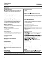
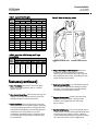
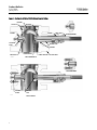
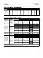
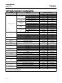
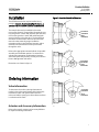
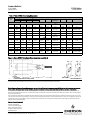
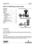
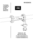
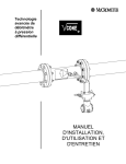
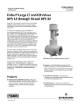
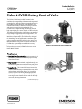
Product Bulletin CV500 Valve 51.3:CV500 January 2013 D101606X012 Fisherr CV500 Rotary Control Valve The Fisher CV500 Cam Vee-Ballt control valve combines the rangeability of the cammed-segmented V-notched ball, with the inherent ruggedness found in the V500 heavy duty bearings, seals and body. This combination provides a balance of erosion resistance and pressure control for gas and liquids. The unrestricted, straight-through flow design provides high capacity for gas, steam, liquids, or fibrous slurries. The flanged and flangeless valves feature streamlined flow passages, rugged metal trim components, and a self-centering seat ring (figures 1 and 2). With these components, the CV500 valve, designed for throttling or on-off applications, combines globe valve ruggedness with the efficiency of a rotary valve. Matched with a Fisher power or manual actuator, the CV500 valve dependably controls fluids in many process industries. Unless otherwise noted, all NACE references are to NACE MR0175-2002. W8192-2 FLANGED VALVE WITH FISHER 1052 ACTUATOR AND FIELDVUE™ DVC6200 DIGITAL VALVE CONTROLLER Features Excellent Flow Characteristic–Precise contouring of V-notch ball provides a modified equal percentage flow characteristic. High Capacity–Unrestricted, straight-through, flow design provides greater capacity than many conventional globe and rotary eccentric plug valves. Long Seat Life–The V-notch ball cams into and out of the seat minimizing contact with the seat ring for reduced wear and friction (figure 3). V-notch ball doesn't contact seat during throttling operation. S31600 (316 stainless steel) or R30006 (Alloy 6) seat ring has two shutoff surfaces and can be easily reversed, reducing downtime. (continued on page 3) www.Fisher.com W5000-1 WAFER VALVE WITH FISHER 1066 ACTUATOR Product Bulletin CV500 Valve 51.3:CV500 January 2013 D101606X012 Specifications Available Configuration J Flanged or J flangeless valve body assembly with reversible(1) metal seat ring and splined shaft. See tables 2 and 3. Valve Sizes NPS J 3, J 4, J 6, J 8, J 10, and J 12. DN 80, 100, 150, 200, 250 and 300 are also available. End Connection Style and Rating J Raised-face flanges or J ring-type joint flanges (ASME B16.5). Valve bodies with DIN PN10 through PN100 flanges also available. Various flangeless valve sizes are available in certain ASME and DIN ratings. See tables 2 and 3 for ASME and DIN availability. Maximum Inlet Pressure(2) Consistent with applicable ASME or DIN flange ratings Maximum Pressure Drops(2) See table 4 for both forward and reverse flow pressure drops Shutoff Classification Class IV per ANSI/FCI 70-2 and IEC 60534-4, (0.01% of valve capacity at full travel) for either flow direction Construction Materials See table 5 Material Temperature Capability(2) See table 5 Flow Characteristic Modified equal percentage Flow Direction J Forward (normal) flow is into the convex side of the V-notch ball J Bidirectional flow is into either side of the V-notch ball Flow Coefficients See Fisher Catalog 12 Flow Coefficient Ratio(3) 200 to 1 Actuator Mounting J Right-hand or J left-hand as viewed from the upstream side of the valve. Mounting position depends on the desired open valve position and flow direction required by operating conditions. For more information, see the Installation section. Valve V-Notch Ball Rotation Counterclockwise to close (when viewed from the actuator side of the valve body) through 90 degrees of V-notch ball rotation Valve Body/Actuator Action With diaphragm or piston rotary actuator, field-reversible between J push-down-to-close (extending actuator rod closes valve body) and J push-down-to-open (extending actuator rod opens valve body) Packing Constructions PTFE V-Ring: With one carbon-filled PTFE conductive packing ring in J single, J double, or J leak-off arrangements Braided PTFE Composition and Graphite Ribbon: With one graphited composition conductive packing ring in J single, J double, or J leak-off arrangements Graphite Ribbon Packing Rings: In J single, J double, or J leak-off arrangements ENVIRO-SEALt: J PTFE or J Graphite in single arrangements Approximate Weights See table 1 Dimensions See figure 4; face-to-face dimensions conform to ISA S75.04. IEC 60534-3-2 face-to-face dimensions are equivalent to S75.04 face-to-face dimensions. Options J Sealed bearing constructions, J line flange bolts (for flangeless valve bodies), J purged bearings 1. The reversible seat is not available in every trim material. Consult your Emerson Process Management sales office. 2. The pressure or temperature limits in the referenced tables or figures, and in any applicable code limitation, should not be exceeded. 3. Ratio of maximum flow coefficient to minimum usable flow coefficient. May also be called rangeability. 2 Product Bulletin CV500 Valve 51.3:CV500 January 2013 D101606X012 Table 1. Approximate Weights VALVE SIZE, NPS Figure 1. Detail of Seat Ring Design FLANGED CL150 CL300 FLANGELESS CL600 CL150 CL300 CL600 16 kg 3 19 24 26 16 16 4 36 42 50 34 34 34 6 54 69 93 50 50 --- 8 79 98 135 57 68 --- 10 --- 208 --- --- --- --- 12 --- 253 --- --- --- --35 FACE SEAL SECTION Pounds 3 42 52 57 35 35 4 79 93 111 75 75 75 6 120 152 204 110 110 --- 8 175 217 298 125 150 --- 10 --- 458 --- --- --- --- 12 --- 558 --- --- --- --- Table 2. Valve Size, ASME Ratings, and Flange Compatibility ASME VALVE SIZE, NPS CL150 CL300 CL600 CL150 CL300 CL600 3 4 6 8 10 12 X X X X X X X X X X X X X X X X ——— ——— X X X X ——— ——— X X X X ——— ——— X X ——— ——— ——— ——— FLANGED FLANGELESS FORWARD FLOW SHUTOFF 42B3375-A A5685-1 REVERSE FLOW SHUTOFF Simple Assembly and Maintenance–No special orientation, precision clamping or repetitive centering of V-notch ball and seat ring is required when tightening the retainer, promoting accurate alignment and easy assembly. Sour Service Capability–Trim and bolting materials are available for applications handling sour fluids and gases. These constructions comply with the requirements of NACE MR0175-2002. Rugged Construction–Durable, solid metal seat ring and ball shut off tightly. Oversized shaft diameters and rugged trim parts allow high pressure drops. Reliable Performance–The seat ring design (figure 1) self-centers, self-laps, and dynamically aligns with V-notch ball, giving superior cycle life. Optional sealed metal bearings help prevent particle buildup and valve shaft seizure in severe applications. X indicates availability. Features (continued) One-Piece Body–Valve body is cast in one piece. There are no body gaskets to leak as a result of pipeline stresses. Operational Versatility–Self-centering seat ring and rugged V-notch ball allow forward or reverse flow with tight shutoff in either flow direction. Easy Installation–Integral valve flanges mate with many different classes of pipeline flanges, satisfying a variety of piping requirements. Flanges eliminate exposed line flange bolting, shorten alignment and installation time, and promote secure valve installations and piping integrity. Flangeless valves are automatically self-centering on line bolting for easy installation. 3 Product Bulletin CV500 Valve 51.3:CV500 January 2013 D101606X012 Figure 2. Sectionals of Fisher CV500 Rotary Control Valves RETAINER FACE SEALS SEAT RING PACKING BEARING FOLLOWER SHAFT DRIVE SHAFT SEALED BEARING BEARING STOP BEARING GROOVE PIN TAPER AND EXPANSION PIN THRUST WASHER VALVE BODY NPS 3 THROUGH 8 W5793-1 / IL SEALED BEARING BOTTOM FLANGE W5794-1 4 GROOVE PINS NPS 10 AND 12 Product Bulletin CV500 Valve 51.3:CV500 January 2013 D101606X012 Table 3. Valve Size, DIN Ratings, and Flange Compatibility VALVE SIZE, DN 80 100 150 200 250 300 DIN Flanged Flangeless PN 10 PN 16 PN 25 PN 40 PN 63 PN 100 PN 10 PN 16 PN 25 PN 40 PN 63 PN 100 X X X X ——— ——— X X X X ——— ——— X X X X X X X X X X X X X X X X ——— ——— X X X X ——— ——— X X X X ——— ——— X X X X ——— ——— X X X X ——— ——— X X X X ——— ——— X ——— ——— ——— ——— ——— ——— ——— ——— ——— ——— ——— X indicates availability. Table 4. Maximum Allowable Shutoff Pressure Drops(2) VALVE BODY MATERIAL BEARING MATERIAL WCC steel S44004 (440C SST) R30006 (Alloy 6) WCC Steel, DIN 1.0619 steel, CF8M (316 SST), DIN 1.4581 SST, or CF3M(3) (316L SST) PTFE/compositionlined S31603(3) (S316L SST) TEMPERATURE, VALVE SIZE 3 4 6 R30006 (Alloy 6) WCC Steel, DIN 1.0619 steel, CF8M (316 SST), DIN 1.4581 SST, or CF3M(3) (316L SST) PTFE/compositionlined S31603(3) (S316L SST) 12 -29 to 149 41.4 41.4 41.4 24.1 24.1 27.6 41.4 41.4 41.4 23.8 24.1 27.6 204 to 316 41.4 41.4 41.4 23.1 24.1 27.6 -46(1) to 204 41.4 41.4 20.7 15.2 24.1 27.6 204 to 260 41.4 41.4 20.7 15.2 24.1 27.6 260 to 316 41.4 41.4 20.7 15.2 24.1 27.6 -46(1) to 93 41.4 41.4 41.4 24.1 31 34.5 31 34.5 31 34.5 31 34.5 93 to 149 149 to 204 41.4 41.4 41.4 41.4 24.1(4) 41.4 23.1(5) 23.8(4) 41.4 22.1(5) 23.4(4) 41.4 41.4 41.4 -20 to 300 600 600 600 350 350 400 300 to 400 600 600 600 345 350 400 400 to 600 600 600 600 335 350 400 -50(1) to 400 600 600 300 220 350 400 400 to 500 600 600 300 220 350 400 500 to 600 600 600 300 220 350 400 -50(1) to 200 600 600 600 350 450 500 450 500 450 500 450 500 21.7(5) Psi _F WCC steel 10 149 to 204 204 to 232 S44004 (440C SST) 8 Bar _C 200 to 300 600 600 600 300 to 400 600 600 600 400 to 450 600 600 600 350(4) 335(5) 345(4) 320(5) 340(4) 315(5) 1. -29_C (-20_F) for WCC steel valve body material. 2. The pressure or temperature limits in this table or in any applicable code limitation, should not be exceeded. 3. Fisher standard material offerings in Europe only. 4. S17400 (17-4PH SST) shaft only. 5. ASME SA-479 Grade XM-19 stainless steel shaft only. Pressure drops appropriate for both shaft materials. 5 Product Bulletin CV500 Valve 51.3:CV500 January 2013 D101606X012 Table 5. Materials of Construction and Temperature Capabilities PART NAME WCC steel bodies DIN 1.0619 steel bodies Valve body and retainer CF8M (316 SST) bodies -29 to 427 -20 to 800 R30006 (Alloy 6) retainer -29 to 427 -20 to 800 CF8M (316 SST) retainer -29 to 260 -20 to 500 CB7Cu-1 (17-4PH) retainer -26 to 427 -14 to 800 R30006 (Alloy 6) retainer -26 to 427 -14 to 800 CF3M (316L SST) retainer -26 to 260 -14 to 500 CF8M retainer -198 to 427 -325 to 800 R30006 (Alloy 6) retainer -46 to 316 -50 to 600 CF8M with CoCr-A (Alloy 6) bore -198 to 427 -325 to 800 -319 to 800 CF3M retainer -195 to 427 R30006 (Alloy 6) retainer -46 to 316 -50 to 600 CF3M with CoCr-A bore -198 to 427 -319 to 800 CF3M(1) (316L SST) bodies CF3M retainer -198 to 427 -325 to 800 R30006 (Alloy 6) retainer -46 to 316 -50 to 600 CF3M with CoCr-A bore -198 to 427 -325 to 800 Ball Drive shaft and follower shaft Taper and expansion pins (NPS 3 through 8) Groove pin Bearings O-rings(2) (for S44004 or R30006 sealed bearings) CF8M -198 to 538 -325 to 1000 R30006 (Alloy 6) -198 to 538 -325 to 1000 CF8M with CoCr-A seat -198 to 538 -325 to 1000 CF3M(1) -198 to 454 -325 to 850 CF3M(1) with CoCr-A seat -198 to 454 -325 to 850 Chrome plated CF3M -198 to 316 -325 to 600 Chrome plated CF3M with CoCr-A V-notch -198 to 316 -325 to 600 S17400 (17-4PH SST) -62 to 427 -80 to 800 ASME SA479 grade S20910 -198 to 538 -325 to 1000 ASME SA479 grade S20910 -198 to 538 -325 to 1000 -325 to 1000 S31600 -198 to 538 S44004 (440C SST) -29 to 427 -20 to 800 R30006 (Alloy 6) -198 to 538 -325 to 1000 PTFE/composition lined S31603 -46 to 232 -50 to 450 Fluorocarbon -18 to 204 0 to 400 Nitrile -29 to 93 -20 to 200 S31600 -198 to 538 -325 to 1000 S31603(1) -198 to 454 -325 to 850 S17700 for S17400 drive shaft -198 to 427 -325 to 800 Alloy 6B for S20910 drive shaft -198 to 538 -325 to 1000 N07718 -198 to 538 -325 to 1000 S31600 -198 to 538 -325 to 1000 S31603(1) -198 to 454 -325 to 850 PTFE V-ring with one carbon-filled PTFE ring(3) -46 to 260 -50 to 500 Braided PTFE composition with one graphite filament ring(4) -73 to 260 -100 to 500 Graphite ribbon -198 to 538 -325 to 1000 S31600 -198 to 538 -325 to 1000 SA-193-B7 studs and SA-194-2H nuts -46 to 427 -50 to 800 SA-193-B7M studs and SA-194-2HM nuts -29 to 427 -20 to 800 SA-193-B8M studs and SA-194-8M nuts -198 to 538 -325 to 1000 S31600 -198 to 538 -325 to 1000 S31603(1) -198 to 454 -325 to 850 Bearing stop Thrust washer Face seals Retainer gasket Packing follower Studs and nuts Packing box ring 1. Fisher standard material offerings in Europe only. 2. For sealed bearing constructions. 3. Carbon-filled PTFE ring used for grounding purposes. 4. Graphite filament ring used for grounding purposes. 6 CB7Cu-1 (17-4PH) retainer DIN 1.4581 SST bodies Seat ring Packing MINIMUM TO MAXIMUM TEMPERATURE _C _F MATERIAL Product Bulletin CV500 Valve 51.3:CV500 January 2013 D101606X012 Installation Figure 3. Eccentric V-Notch Ball Rotation The CV500 control valve may be installed in any position. However, for best shutoff performance, a position with the shaft horizontal is recommended. The control valve may be installed in forward or reverse flow direction. Forward flow (through the seat ring and past the V-notch ball) tends to open the valve; reverse flow (past the V-notch ball and through the seat ring) tends to close the valve. The forward flow direction is recommended. Refer to the instruction manual to determine the proper installation orientation of the V-notch ball and actuator, and to determine the flow direction of the process fluid through the valve. VALVE BODY CENTERLINE SHAFT CENTERLINE Refer to the appropriate actuator bulletin for possible assembly and installation options. For assistance in selecting the appropriate combination of actuator action and open valve position, consult your Emerson Process Management sales office. VALVE BODY CENTERLINE Dimensions are shown in figure 4. SHAFT CENTERLINE Ordering Information Valve Information To determine what valve ordering information is needed, refer to the specifications table. Review the information under each specification and in the referenced tables; specify your choice whenever there is a selection to be made. Actuator and Accessory Information VALVE BODY CENTERLINE SHAFT CENTERLINE B2333 Refer to the specific actuator and accessory bulletins for required ordering information. 7 Product Bulletin CV500 Valve 51.3:CV500 January 2013 D101606X012 Table 6. Fisher CV500 Valve Body Dimensions VALVE SIZE DIMENSIONS A RF B RTJ RF RTJ D K S (Shaft Dia)(1) T U W mm 3 165 165 83 83 213 200 25.4 25.4 x 19.1 152 32 14 4 194 194 97 97 208 216 31.8 235 46 18 235 46 5/8-inch 11 UNC 6 229 229 114 114 208 270 38.1 38.1 x 31.8 8 243 243 121 121 208 318 38.1 235 46 5/8-inch 11 UNC 10 297 312 148 156 356 353 44.5 273 51 3/4-inch 10 UNC 408 53.8 53.8 x 50.8 273 51 3/4-inch 10 UNC 12 338 354 169 177 356 3 6.50 6.50 3.25 3.25 8.44 7.88 1.00 1.00 x 0.75 6.00 1.25 0.56 4 7.62 7.62 3.81 3.81 8.19 8.50 1.25 9.25 1.81 0.69 8.19 10.62 1.50 1.50 x 1.25 9.25 1.81 5/8-inch 11 UNC Inches 6 9.00 9.00 4.50 4.50 8 9.56 9.56 4.78 4.78 8.19 12.50 1.50 9.25 1.81 5/8-inch 11 UNC 10 11.68 12.30 5.84 6.15 14.00 13.91 1.75 10.75 2.00 3/4-inch 10 UNC 16.07 2.12 2.12 x 2.00 10.75 2.00 3/4-inch 10 UNC 12 13.31 13.93 6.66 6.97 14.00 1. Shaft diameter versus spline diameter. Figure 4. Fisher CV500 Valve Body Dimensions (also see table 6) U U B A A3289-1 S CL150, K 300, OR 600 FLANGELESS OR WITH RF OR RTJ FLANGES D W NPS 3 AND 4 W NPS 6 THROUGH 12 Note: For dimensions of valves with DIN (or other) end connections, contact your Emerson Process Management sales office. Neither Emerson, Emerson Process Management, nor any of their affiliated entities assumes responsibility for the selection, use or maintenance of any product. Responsibility for proper selection, use, and maintenance of any product remains solely with the purchaser and end user. Fisher, Vee-Ball, and ENVIRO-SEAL are marks owned by one of the companies in the Emerson Process Management business unit of Emerson Electric Co. Emerson Process Management, Emerson, and the Emerson logo are trademarks and service marks of Emerson Electric Co. All other marks are the property of their respective owners. The contents of this publication are presented for informational purposes only, and while every effort has been made to ensure their accuracy, they are not to be construed as warranties or guarantees, express or implied, regarding the products or services described herein or their use or applicability. All sales are governed by our terms and conditions, which are available upon request. We reserve the right to modify or improve the designs or specifications of such products at any time without notice. Emerson Process Management Marshalltown, Iowa 50158 USA Sorocaba, 18087 Brazil Chatham, Kent ME4 4QZ UK Dubai, United Arab Emirates Singapore 128461 Singapore www.Fisher.com E 8 1991, 2013 Fisher Controls International LLC. All rights reserved.