1
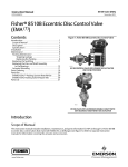
Product Bulletin 8510/8510B Valve 51.6:edisc (EMA) February 2013 D100066X012 Fisherr 8510 and 8510B Eccentric Disc Control Valves (EMA) Fisher 8510 and 8510B eccentric disc valves feature an eccentrically mounted disc and a PTFE or 316 stainless steel seal ring. The pressure-assisted seal ring provides excellent shutoff against pressure applied in either direction. The 8510B is a multi-class rated valve, available in NPS 2 through 12, and PN10 through PN100 compatible (compatibility varies with size and class, see table 1). The 8510 is rated for CL150, available in NPS 14 through 24, and PN10 and PN16 compatible (compatibility varies with size and class, see table 1). These valves combine with a variety of power and manual actuators to form reliable, high-performance control valves suited for many liquid and gas applications requiring extremely low leakage. Constructions are available for temperatures up to 538C (1000F). W4739-2 Eccentric Disc Control Valve with Fisher 1052 Actuator and 3610J Positioner Unless otherwise noted, all NACE references are to NACE MR0175-2002. Features Sour Service Capability–Materials are available for applications involving sour service. These materials comply with the requirements of NACE MR0175-2002. Excellent Flow Control–The eccentrically mounted disc design provides an approximately linear flow characteristic and can be used for on/off or throttling control applications through 90 degrees of disc rotation. Optional disc stop on 8510B provides seal protection. (continued on page 3) www.Fisher.com W9264-1 Fisher 8510B with Alternate Double D Shaft and 1035/El-O-Matic Actuator Product Bulletin 8510/8510B Valve 51.6:edisc (EMA) February 2013 D100066X012 Specifications Valve Sizes and End Connection Style 8510B: NPS J 2, J 4, J 6 and J 8 (PN10 through PN100) - CL150, 300 or 600 ASME flange compatibility, J 10 and J 12 (PN10 through PN40) CL150 ASME flange compatibility Flow Direction Standard (forward flow) is with the seal retainer facing upstream; reverse flow is permissible within specified limitations Flow Coefficients See table 1 8510 flangeless valves: NPS J 14 (PN10 and PN16), J 16 (PN16), J 18, J 20 (PN16) and J 24 (PN16) CL150 ASME flange compatibility for NPS 14 through 24 Flow Coefficient Ratio(2) Also see table 1. Noise Levels Maximum Inlet Pressures(1) WCC Steel, CF3M Stainless Steel (316L SST), and CN7M (Alloy 20) Valve Bodies: Consistent with applicable pressure-temperature ratings in table 2, unless limited by pressure drop/temperature capabilities in tables 6, 7, 8, 9 and 10 or temperature capabilities in table 11 M35-1 Valve Bodies: As shown in table 2, unless further limited by pressure drop/temperature capabilities in table 10 or temperature capabilities in table 11 Maximum Pressure Drops(1) Steel Valve Bodies (8510 and 8510B): See table 6 or 7 CF8M Stainless Steel Valve Bodies (8510): See tables 8 and 9 Alloy Valve Bodies (8510B): See table 10 Shutoff Classifications per ANSI/FCI 70-2 and IEC 60534-4 PTFE Seal Ring: Bidirectional shutoff to Class VI is standard 316 Stainless Steel Seal Ring: 0.001% of maximum valve capacity (one tenth of Class IV) Construction Materials See tables 3, 4, and 5 Material Temperature Capabilities(1) See table 11 Flow Characteristic Approximately linear 100 to 1 See Catalog 12 for sound pressure level prediction Disc Rotation Clockwise to close (when viewed from actuator side of valve) through 90 degrees of disc rotation Actuator Valve Action With diaphragm or piston rotary actuator, field-reversible between J push-down-to-open (extending actuator rod opens valve) and J push-down-to-close (extending actuator rod closes valve) With 1035 Rack and Pinion actuator with spring return or double acting action, field-reversible between J fail-to-open and J fail-to-close Valve Classification J Face-to-face dimensions of NPS 3 through 6 in CL150 and 300, and face-to-face dimensions of NPS 8 through 24 in CL150, meet API 609 standards for face-to-face dimensions of narrow flangeless and single-flange valves J DIN face-to-face dimensions for all sizes meet DIN 3202 Part 3/K2, and J JIS B2210 standard face-to-face dimensions are available on request. Mating Flange Capabilities All size compatible with welding-neck and slip-on flanges (schedule 80 or lighter for 8510B NPS 2 through 12; schedule 40 or lighter for 8510 NPS 14 through 24) Shaft Diameters and Approximate Weights See figures 7 and 8 Options J Line flange bolting, J FGM line flange gaskets 1. The pressure/temperature limits in this bulletin and any applicable standard or code limitation should not be exceeded. 2. Ratio of maximum flow coefficient to minimum useable flow coefficient. 2 Product Bulletin 8510/8510B Valve 51.6:edisc (EMA) February 2013 D100066X012 ENVIRO-SEAL Packing System Specifications Available Packing J ENVIRO-SEAL PTFE Packing System J ENVIRO-SEAL Graphite Packing System Maximum Temperature/Pressure Limits(1) Maximum Application Temperature/Pressure Limits to meet EPA Fugitive Emission Standard of 100 ppm(2): For ENVIRO-SEAL PTFE Packing Systems: Up to 232C (450F) at the ASME class rating of the valve. For ENVIRO-SEAL Graphite Packing Systems: Up to 316C (600F) at the ASME class rating of the valve Material Temperature Range: For ENVIRO-SEAL PTFE Packing Material: -46 to 232C (-50 to 450F) For ENVIRO-SEAL Graphite Packing Material: Up to 316C (600F) Construction Materials(3) PTFE Packing Systems: Packing Rings: PTFE V-ring(4) Male and Female Adaptor Rings: Carbon-filled PTFE V-ring Anti-Extrusion Rings: High strength polymer Packing Box Rings: S31600 (316 SST) Graphite Packing Systems: Packing Rings: Graphite Anti-Extrusion Rings: Carbon Packing Box Rings: S31600 (316 SST) Spring Pack Components: O-Ring: Nitrile. The O-ring serves as an assembly convenience to hold the springs in position on the follower. Packing Follower: S31600 with carbon-filled PTFE liner Springs: N07718 Packing Flange: S31600 (316 SST) Packing Box Studs: Strain-hardened S31600, SA-193-B8M Packing Box Nuts: S31600 SA-194-8M 1. The pressure/temperature limits in this bulletin and any applicable standard or code limitation for valve should not be exceeded. 2. The Environmental Protection Agency (EPA) has set a limit of 100 parts per million (ppm) for fugitive emissions from a valve. 3. For other materials of construction, see table 3. 4. In vacuum service it is not necessary to reverse the ENVIRO-SEAL PTFE packing rings. Features (continued) Improved Environmental Capabilities–The optional ENVIRO-SEALt packing systems, shown in figure 6, are designed with very smooth stem surfaces, and live loading provides improved sealing, guiding, and loading force transmission. The seal of the ENVIRO-SEAL system can control emissions to below the EPA (Environmental Protection Agency) limit of 100 ppm (parts per million) for valves. Lost Motion Minimized–For 8510, the taper pin/disc connection and the splined valve shaft with clamped lever and single pivot linkage reduce lost motion between the actuator and valve. For 8510B, the taper key/disc connection and the splined valve shaft with clamped lever and single pivot linkage reduce lost motion between the actuator and valve. Greater Capacities and Lower Operating Torques–The contoured disc increases flow capacity and reduces operating torque at peak angles of disc opening. 3 Product Bulletin 8510/8510B Valve 51.6:edisc (EMA) February 2013 D100066X012 Construction Features 4 Field-Reversible Valve Action–The actuator/valve assembly action can be converted from push-down-to-open to push-down-to-close, or vice versa, without additional parts. PTFE seal ring with pressure-assisting sealing action (figure 5) are designed to provide shutoff regardless of flow direction. Reliable Flange Gasketing Surface–The seal retainer cap screws or retention clips are outside the gasket surface of the seal retainer, and spiral wound or flat sheet gaskets can be installed between the uninterrupted seal retainer face and the pipeline flange. Easy Installation–Centering holes (figures 1, 2 and 3) engage the line flange bolts to simplify installation and provide for centering of the valve in the pipeline. Self-Flushing Action–With standard right-hand actuator mounting, the bottom edge of the disc opens downstream away from the seal, and the flow stream flushes sediment from the seal. Long Seal Life–The opening and closing path of the eccentric disc (figure 4) minimizes disc contact with the seal ring, thereby reducing seal wear, undue friction, and seating torque requirements. Double D Shaft–8510B valves in NPS 2 through 12 are available with double D shaft end designed to accept the 1035 Rack and Pinion Actuator and other quarter-turn actuators. Shaft Retention–Redundant shaft protection is provided with 8510B valves with the double D drive shaft. The packing follower and stepped shaft interact to provide the redundant shaft retention. Integral Shaft-to-Body Bonding–Standard valve construction includes conductive packing to provide electrical bonding for hazardous area applications. Exceptional Shutoff at High Pressure Drops–Both the 316 stainless steel seal ring and the bidirectional Product Bulletin 8510/8510B Valve 51.6:edisc (EMA) February 2013 D100066X012 Figure 1. Typical Fisher 8510B Construction Detail RETAINER CLIP CENTERING HOLE VIEW A SEE VIEW A TAPER KEY SEAL RETAINER SEAL RING DISC SEAL RING ASSEMBLY SPRING BEARING SPACER VALVE BODY PTFE SEAL 41B6064-A 41B6101-A B2303* 316 STAINLESS STEEL SEAL Figure 2. Typical Fisher 8510B Construction Detail with Double D Shaft TAPER KEY CENTERING HOLE REDUNDANT SHAFT RETENTION DEVICE BEARING SPACER 39b8285-A E0781 5 Product Bulletin 8510/8510B Valve 51.6:edisc (EMA) February 2013 D100066X012 Figure 3. Construction of Fisher 8510 CENTERING HOLE 48A5626-A B1691-3 Figure 4. Comparison of Disc Action SEAL RING (PTFE CONSTRUCTION SHOWN) ECCENTRIC DISK PATH OF ROTATION CONVENTIONAL DISK PATH OF ROTATION ECCENTRIC DISK CENTER OF ROTATION SIDE VIEW – DISK FULLY CLOSED 6 ECCENTRIC DISK CENTERLINE OF VALVE BODY CONVENTIONAL DISK CENTER OF ROTATION A2867-2 CONVENTIONAL DISK VALVE BODY BOTTOM VIEW – DISK FULLY OPENED Product Bulletin 8510/8510B Valve 51.6:edisc (EMA) February 2013 D100066X012 Figure 5. Action of Bidirectional PTFE Seal RIng (Top) and Metal Seat Ring (Bottom) VALVE BODY SEAL RING SEAL RETAINER SPRING DIRECTION OF PRESSURE STANDARD FLOW DIRECTION DISC VALVE BODY SEAL RING SEAL RETAINER DIRECTION OF PRESSURE STANDARD FLOW DIRECTION DISC DISC CLOSING OR OPENING AND NOT IN CONTACT WITH SEAL RING DISC CLOSED AND IN CONTACT WITH SEAL RING ACTION OF SEAL RING WITH PRESSURE APPLIED FROM BOTH DIRECTIONS B1558-3 Note: 1 Arrow indicates disc position with no pressure. 7 Product Bulletin 8510/8510B Valve 51.6:edisc (EMA) February 2013 D100066X012 Table 1. Flow Coefficients and ASME Rating and Flange Compatibility VALVE BODY SIZE, NPS Cv WITH NORMAL FLOW AND DISC WIDE OPEN (90 DEGREES ROTATION) 2 91.7 3 232 4 459 ASME RATING COMPATIBILITY– STEEL, STAINLESS STEEL, AND ALLOY 20 VALVE BODIES VALVE DESIGNATION– M35-1(1) ASME FLANGE COMPATIBILITY PN FLANGE COMPATIBILITY 8510B CL150, 300, and 600 CL150/300/ 600 CL150, 300, and 600 PN10, PN16, PN25, PN40, PN63 and PN100 6 907 8 1740 10 3570 CL150 CL300 CL150 CL300 CL150 CL300 PN10 and PN16 PN25 and PN40 12 4880 CL150 CL300 CL150 CL300 CL150 CL300 PN10 and PN16 PN25 and PN40 14 7040 16 9650 18 12,100 20 14,500 PN16(2) 24 21,800 PN16(2) 8510 PN10 and PN16(2) PN16(2) CL150 --- --- CL150 1. M35-1 valve bodies are not included in ASME B16.34. See table 2 for pressure/temperature information for M35-1 valve bodies. The designations CL150, 300, and 600 for these valve bodies are used only to indicate relative pressure-retaining capabilities and are not ASME pressure/temperature rating class designations. 2. Consult your Emerson Process Management sales office for pressure/temperature ratings of these valves. Table 2. Maximum Allowable Inlet Pressures for M35-1 Valve Bodies(1) TEMPERATURE M35-1(1) 150(1) 300(1) 15.8 13.8 13.1 12.7 12.3 41.3 36.5 34.1 33.1 33.0 230 200 190 185 178 600 530 495 480 478 Bar C -46 to 38 93 149 204 232 82.7 72.7 68.2 65.8 65.7 Psig F -50 to 100 200 300 400 450 600(1) 1200 1055 990 955 953 1. This material is not listed in ASME B16.34. Also see the installation information. The designations CL150, 300, and 600 are used only to indicate relative pressure-retaining capabilities and are not ASME pressure-temperature rating class designations. 8 Product Bulletin 8510/8510B Valve 51.6:edisc (EMA) February 2013 D100066X012 Table 3. Standard Construction Materials Part Material Valve Body(1) 8510: WCC Steel, CG8M (316 stainless steel), M35-1(2), or CN-7M (alloy 20) 8510B: WCC Steel, CF3M (316L SST), M35-1(2), CN7M (alloy 20), 1.0619 steel, or 1.4581 stainless steel 8510: WCC Steel (A216), S31603 (316L stainless steel) (both with chrome-plated seating surfaces), M35-1, or alloy 20 CN-7M 8510B: WCC Steel (A216), M35-1, CN7M (alloy 20), S31603 (316L SST), or Cr PI S31603 (Cr Pl 316L SST) PTFE with 316 stainless steel, N04400, or alloy 20 spring Disc(1) Seal(1) 316 stainless steel seal and backup rings with graphite gaskets bonded to them Lined 8510: PTFE(3)/composition lined w/SST jacket, PTFE(3) composition lined w/S31600 (316 SST) jacket, S44004 (440C SST), alloy 6B, silver-plated alloy 6B, filled PTFE(4) w/N04400 jacket, or filled PTFE(4) w/N08020 (alloy 20) jacket 8510B: PTFE(3)/composition lining with S31603 (316L SST), PTFE(4) with S31603 jacket, filled PTFE(4) with N04400 jacket, and filled PTFE(4) with N08020 (alloy 20) jacket All-metal 440C stainless steel, alloy 6B, or silver-plated alloy 6B Bearings(1) 8510: Valve shaft(1) and bearing spacers S17400 (17-4PH SST), S20910, N04400, or alloy 20 8510B: Valve Shaft(1)(6) S17400 (17-4PH), S20910, N05500, N08020 (alloy 20), or S31603 (316L SST) 8510B: Bearing Spacers PTFE/S31603 (316L SST), S17700 (17-7 PH SST), alloy 6B, PTFE/N04400, and PTFE/N08020 (alloy 20) 8510: Taper Pins 8510B: Taper Keys S17400 (17-4PH) and S20910 shafts 8510: S20910 8510B: S20910 SST, N05500, N10276 (alloy 276), or N08020 (alloy 20) Alloy shafts Same material as shaft 8510: Bearing stops (for Steel valve bodies metal bearings and CF8M steel valve bodies non-alloy valve bodies only) 8510B: Bearings stops (for metal bearings and non-alloy valves only) S17400 S31600 (316 stainless steel) S31600 (316 SST) Seal retainer Same material as valve body Packing arrangements Standard packing is available with PTFE packing V-rings with one carbon-filled PTFE conductive ring, PTFE-composition rings with one graphited conductive ring, and preformed graphite ribbon rings. ENVIRO-SEAL packing system is available with PTFE V-rings with one carbon-filled PTFE conductive ring or with graphite packing rings. Packing followers and packing box rings S31600, N04400, or alloy 20 Packing flanges, studs and nuts Plated steel, S31603(5), S31600, CF8M, N04400, or alloy 20 1. See table 4 for acceptable trim material combinations. 2. This is not an ASME B16.34 or ASME code-approved material. Also see the Installation section. 3. Reinforced PTFE in phenolic resin, Emerson Process Management designation is FMS 30B4. 4. PTFE with selected fillers. Emerson Process Management designation is FMS 30B5. 5. S31603 is available for 8510B only 6. 8510B valve shafts with Double D end are available only in 17-4PH SST, 316L SST or S20910. 9 Product Bulletin 8510/8510B Valve 51.6:edisc (EMA) February 2013 D100066X012 Table 4. Trim Combinations with Standard Construction Materials Disc Material Shaft Material Bearing Material 8510: WCC steel with chrome-plated seating surfaces 8510B: WCC steel with chrome-plated seating surface or S31603 (316L SST)(1) Seal Material Acceptable Valve Body Material PTFE S17400 (17-4PH stainless steel) 8510: S31603 (316L SST) with chrome-plated seating surfaces S17400 8510B: S31603 (316L SST) with chrome-plated seating surfaces or S31603 (316L SST) without plating with PTFE seal only S20910 Trim Number 1 PTFE/composition-lined, w/SST jacket 316 stainless steel S44004 (440C SST) 316 stainless steel PTFE/composition-lined w/SST jacket 316 stainless steel PTFE PTFE PTFE/composition-lined S31600 (316 SST) jacket 316 stainless steel S44004 316 stainless steel Silver-plated alloy 6B 316 stainless steel Alloy 6B 316 stainless steel PTFE/composition-lined with S31600 jacket 316 stainless steel Silver-plated alloy 6B 316 stainless steel PTFE 5 Steel 9 2 Steel 6 8510: Steel or CF8M 8510B: Steel or CF3M (316 SST) Steel 8510: Steel or, CF8M 8510B: Steel or CF3M (316 SST) 8510: Steel or CF8M 8510B: Steel or CF3M (316 SST) 4 8 10 12 14 3 7 11 Alloy 6B 316 stainless steel M35-1 N05500 Filled PTFE(2) w/ N04400 jacket PTFE M35-1 or steel 15(3) 13 Alloy 20 CN7M Alloy 20 Filled PTFE(2) w/ N08020 (alloy 20) jacket PTFE Alloy 20 CN-7M 17(3)(4) 1. Steel disc not available in the NPS 2 and 3 valves. 2. PTFE with selected fillers. Emerson Process Management designation is FMS 30B5. 3. This trim not available in the 8510 NPS 14 through 24 valves. 4. This trim not available with the Double D shaft version of the 8510B. Table 5. Trim NT3 Part Materials for Compliance with NACE MR0175-2002 (Sour Service) Specifications Valve Body Disc Seal 8510: CG8M (317 stainless steel) with chromeplated seating 8510: Steel or surfaces PTFE seal CF8M (316 8510B: with stainless steel) S31603 (316 N05500 8510B: Steel or SST) with spring CF3M (316L SST) chrome-plated seating surfaces or S31603 (316L SST) 10 Bearings 8510: Filled PTFE w/ S31600 (316 SST) jacket 8510B: PTFE/ compositionlined S31603 (316L SST) Valve Shaft S20910 Taper Pins S20910 Packing Packing Followers and Packing Box Rings Packing Flanges Packing Flange Bolting 8510: S31600 PTFE V-ring 8510: steel (316 stainless Grade B7 with one 8510B: steel) steel studs carbon-filled S31600 (316 8510B: S31600 and Grade PTFE SST) or (316 SST) or 2H steel conductive S31603 S31603 (316L nuts packing ring (316L SST) SST) Product Bulletin 8510/8510B Valve 51.6:edisc (EMA) February 2013 D100066X012 Figure 6. Typical ENVIRO-SEAL Packing Arrangements for Rotary Valves PACKING BOX STUD SPRINGS VALVE BODY ACTUATOR MOUNTING YOKE ANTIEXTRUSION RINGS VALVE SHAFT VALVE SHAFT PACKING FLANGE PACKING BOX RING YOKE BEARING PACKING FLANGE PACKING BOX RING PTFE PACKING V-RINGS SHOWN PACKING FOLLOWER W5806-1 SINGLE PTFE PACKING SPRINGS PACKING FOLLOWER GRAPHITE PACKING SET W6125-1 GRAPHITE PACKING 11 Product Bulletin 8510/8510B Valve 51.6:edisc (EMA) February 2013 D100066X012 Table 6. Maximum Allowable Shutoff Pressure Drops(1) in Bar for Steel Valve Body Material TABLE 4 OR 5 TRIM NUMBER 1(2), 2, 3, 4, NT3 5(2), 6, 7, 8 9(2), 10 11 12 13 14 15 FLOW DIRECTION Forward or reverse MAX ALLOWABLE SHUTOFF P (PER VALVE BODY SIZE, NPS) TEMP. C -29 to 49 66 93 121 149 191 204 8510B 3 4 6 8 10 12 14 16 18 20 24 56.2 56.2 48.5 38.6 28.7 13.8 10.3 64.5 58.5 48.5 38.6 28.7 13.8 10.3 53.8 53.8 48.5 38.6 28.7 13.8 10.3 57.9 57.9 48.5 38.6 28.7 13.8 10.3 54.6 54.6 48.5 38.6 28.7 13.8 10.3 37.7 37.7 37.7 37.7 28.7 13.8 10.3 41.4 41.4 41.4 38.6 28.7 13.8 10.3 19.7 19.0 17.9 16.9 15.5 13.8 10.3 19.7 19.0 17.9 16.9 15.5 13.8 10.3 19.7 19.0 17.9 16.9 15.5 13.8 10.3 19.7 19.0 17.9 16.9 15.5 13.8 10.3 19.7 19.0 17.9 16.9 15.5 13.8 10.3 232(3) 3.4 3.4 3.4 3.4 3.4 3.4 3.4 3.4 3.4 3.4 3.4 3.4 Forward -29 to 232(3) 51.0 51.0 51.0 51.0 31.0 17.2 17.2 10.3 10.3 10.3 10.3 10.3 Reverse -29 to 232(3) 6.9 6.9 6.9 6.9 6.9 6.9 6.9 6.9 6.9 6.9 6.9 6.9 -29 to 149 19.7(4) 31.5(4) 28.8(4) 20.2(4) 24.3(4) 13.4(4) 9.0(4) 5.3 10.0(4) 6.4 3.8 7.9(4) 204 18.2(4) 29.9(4) 27.4(4) 20.2(4) 24.3(4) 12.8(4) 8.5(4) 4.9 9.5(4) 6.1 3.5 7.5(4) 260 17.3(4) 28.9(4) 26.5(4) 19.6(4) 24.3(4) 12.3(4) 8.2(4) 4.7 9.2(4) 5.8 3.3 7.3(4) 316 16.8(4) 28.3(4) 26.0(4) 19.2(4) 24.0(4) 12.1(4) 8.1(4) 4.6 9.0(4) 5.7 3.2 7.2(4) 371 15.9(4) 27.3(4) 25.1(4) 18.6(4) 23.3(4) 11.7(4) 7.7(4) 4.3 8.8(4) 5.4 3.0 7.0(4) 427 15.0(4) 26.3(4) 24.2(4) 17.9(4) 22.6(4) 11.2(4) 7.4(4) 4.1 8.4(4) 5.2 2.8 6.7(4) -29 to 93 19.7(4) 21.9(4) 18.5(4) 17.0(4) 14.6(4) 9.1(4) 9.0(4) 5.2 7.4(4) 5.7 3.7 6.7 149 17.1(4) 21.9(4) 18.5(4) 17.0(4) 14.6(4) 9.1(4) 8.1(4) 4.6 7.4(4) 5.7 3.2 6.7 204 15.0(4) 21.9(4) 18.5(4) 17.0(4) 14.6(4) 9.1(4) 7.4(4) 4.1 7.4(4) 5.2 2.8 6.7 260 14.6(4) 21.9(4) 18.5(4) 17.0(4) 14.6(4) 9.1(4) 7.2(4) 3.9 7.4(4) 5.1 2.8 6.6 316 13.9(4) 21.9(4) 18.5(4) 17.0(4) 14.6(4) 9.1(4) 7.0(4) 3.8 7.4(4) 4.9 2.6 6.4 371 13.3(4) 21.9(4) 18.5(4) 16.8(4) 14.6(4) 9.1(4) 6.8 3.7 7.4(4) 4.8 2.6 6.3 427 12.6(4) 21.9(4) 18.5(4) 16.3(4) 14.6(4) 9.1(4) 6.6 3.4 7.4(4) 4.6 2.3 6.1 -46 to 149 19.7(4) 21.9(4) 18.5(4) 17.0(4) 14.6(4) 9.1(4) 9.0(4) 5.3 7.4(4) 5.7 3.8 6.7 204 18.2(4) 21.9(4) 18.5(4) 17.0(4) 14.6(4) 9.1(4) 8.5(4) 4.9 7.4(4) 5.7 3.5 6.7 260 17.3(4) 21.9(4) 18.5(4) 17.0(4) 14.6(4) 9.1(4) 8.2(4) 4.7 7.4(4) 5.7 3.3 6.7 316 16.8(4) 21.9(4) 18.5(4) 17.0(4) 14.6(4) 9.1(4) 8.1(4) 4.6 7.4(4) 5.7 3.2 6.7 371 15.9(4) 21.9(4) 18.5(4) 17.0(4) 14.6(4) 9.1(4) 7.7(4) 4.3 7.4(4) 5.4 3.0 6.7 427 15.0(4) 21.9(4) 18.5(4) 17.0(4) 14.6(4) 9.1(4) 7.4(4) 4.1 7.4(4) 5.2 2.8 6.7 -29 to 149 12.3(4) 11.0(4) 9.2(4) 8.5(4) 7.3(4) 4.6 4.6 3.5 3.7 2.8 3.0 3.3 204 12.3(4) 11.0(4) 9.2(4) 8.5(4) 7.3(4) 4.6 4.6 3.5 3.7 2.8 2.8 3.3 260 12.3(4) 11.0(4) 9.2(4) 8.5(4) 7.3(4) 4.6 4.6 3.5 3.7 2.8 2.8 3.3 316 12.3(4) 11.0(4) 9.2(4) 8.5(4) 7.3(4) 4.6 4.6 3.5 3.7 2.8 2.6 3.3 371 12.3(4) 11.0(4) 9.2(4) 8.5(4) 7.3(4) 4.6 4.6 3.5 3.7 2.8 2.6 3.3 427 12.3(4) 11.0(4) 9.2(4) 8.5(4) 7.3(4) 4.6 4.6 3.4 3.7 2.8 2.3 3.3 Forward -29 to 427 12.3 11.0 9.2 8.5 7.3 4.6 4.6 3.5 3.7 2.8 3.0 3.3 Reverse -29 to 427 6.9 6.9 6.9 6.9 6.9 4.6 4.6 3.5 3.7 2.8 3.0 3.3 Forward or reverse -29 to 49 66 93 121 149 191 204 232 52.4 52.4 43.0 38.6 28.7 13.8 10.3 3.4 60.4 58.5 43.0 38.6 28.7 13.8 10.3 3.4 50.3 50.3 43.0 38.6 28.7 13.8 10.3 3.4 57.9 57.9 43.0 38.6 28.7 13.8 10.3 3.4 51.4 51.4 43.0 38.6 28.7 13.8 10.3 3.4 33.4 33.4 33.4 33.4 28.7 13.8 10.3 3.4 33.8 33.8 33.8 33.8 28.7 13.8 10.3 3.4 Forward or reverse Forward or reverse Forward or reverse Forward or reverse 1. Based on valve body assembly material strengths only–actuator torque not considered. 2. This trim not available in the NPS 2, 3, and 4 valves. 3. For hot water or steam service, limit maximum temperature to 207C. 4. Reverse pressure drop is limited to 6.9 bar. 12 8510 2 --- Product Bulletin 8510/8510B Valve 51.6:edisc (EMA) February 2013 D100066X012 Table 7. Maximum Allowable Shutoff Pressure Drops(1) in Psi for Steel Valve Body Material TABLE 4 OR 5 TRIM NUMBER 1(2), 2, 3, 4, NT3 5(2), 6, 7, 8 9(2), 10 11 12 13 14 15 FLOW DIRECTION Forward or reverse MAX ALLOWABLE SHUTOFF P (PER VALVE BODY SIZE, NPS) TEMP. F -20 to 120 150 200 250 300 375 400 8510B 8510 2 3 4 6 8 10 12 14 16 18 20 24 816 816 704 560 416 200 150 935 848 704 560 416 200 150 780 780 704 560 416 200 150 840 840 704 560 416 200 150 792 792 704 560 416 200 150 547 547 547 547 416 200 150 600 600 600 560 416 200 150 285 275 260 245 230 200 150 285 275 260 245 230 200 150 285 275 260 245 230 200 150 285 275 260 245 230 200 150 285 275 260 245 230 200 150 450(3) 50 50 50 50 50 50 50 50 50 50 50 50 Forward -20 to 450(3) 740 740 740 740 450 250 250 150 150 150 150 150 Reverse -20 to 450(3) 100 100 100 100 100 100 100 100 100 100 100 100 -20 to 300 285(4) 457(4) 417(4) 307(4) 353(4) 194(4) 131(4) 77 145(4) 93 55 115(4) 400 264(4) 434(4) 397(4) 293(4) 353(4) 185(4) 124(4) 71 138(4) 88 51 109(4) 500 251(4) 419(4) 384(4) 284(4) 353(4) 179(4) 119(4) 68 133(4) 84 48 106(4) 600 244(4) 411(4) 377(4) 279(4) 348(4) 175(4) 117(4) 66 131(4) 83 47 104(4) 700 231(4) 396(4) 364(4) 270(4) 338(4) 169(4) 112(4) 62 127(4) 79 44 101(4) 800 218(4) 381(4) 351(4) 260(4) 328(4) 163(4) 107(4) 59 122(4) 78 41 97(4) -20 to 200 285(4) 318(4) 268(4) 246(4) 212(4) 132(4) 130(4) 76 107(4) 82 54 97 300 248(4) 318(4) 268(4) 246(4) 212(4) 132(4) 118(4) 67 107(4) 82 47 97 400 218(4) 318(4) 268(4) 246(4) 212(4) 132(4) 107(4) 59 107(4) 75 41 97 500 212(4) 318(4) 268(4) 246(4) 212(4) 132(4) 105(4) 57 107(4) 74 40 96 600 201(4) 318(4) 268(4) 246(4) 212(4) 132(4) 102(4) 55 107(4) 71 38 93 700 193(4) 318(4) 268(4) 246(4) 212(4) 132(4) 99 53 107(4) 69 37 91 800 183(4) 318(4) 268(4) 236(4) 212(4) 132(4) 95 50 107(4) 66 34 88 -20 to 300 285(4) 318(4) 268(4) 246(4) 212(4) 132(4) 131(4) 77 107(4) 82 55 97 400 264(4) 318(4) 268(4) 246(4) 212(4) 132(4) 124(4) 71 107(4) 82 51 97 500 251(4) 318(4) 268(4) 246(4) 212(4) 132(4) 119(4) 68 107(4) 82 48 97 600 244(4) 318(4) 268(4) 246(4) 212(4) 132(4) 117(4) 66 107(4) 82 47 97 700 231(4) 318(4) 268(4) 246(4) 212(4) 132(4) 112(4) 62 107(4) 79 44 97 800 218(4) 318(4) 268(4) 246(4) 212(4) 132(4) 107(4) 59 107(4) 75 41 97 -20 to 300 178(4) 159(4) 134(4) 123(4) 106(4) 66 67 51 53 41 44 48 400 178(4) 159(4) 134(4) 123(4) 106(4) 66 67 51 53 41 41 48 500 178(4) 159(4) 134(4) 123(4) 106(4) 66 67 51 53 41 40 48 600 178(4) 159(4) 134(4) 123(4) 106(4) 66 67 51 53 41 38 48 700 178(4) 159(4) 134(4) 123(4) 106(4) 66 67 51 53 41 37 48 800 178(4) 159(4) 134(4) 123(4) 106(4) 66 67 50 53 41 34 48 Forward -20 to 800 178 159 134 123 106 66 67 51 53 41 44 48 Reverse -20 to 800 100 100 100 100 100 66 67 51 53 41 44 48 Forward or reverse -20 to 120 150 200 250 300 375 400 450 760 760 704 560 416 200 150 50 876 848 704 560 416 200 150 50 730 730 704 560 416 200 150 50 840 840 704 560 416 200 150 50 746 746 704 560 416 200 150 50 484 484 484 484 416 200 150 50 490 490 490 490 416 200 150 50 Forward or reverse Forward or reverse Forward or reverse Forward or reverse --- 1. Based on valve body assembly material strengths only–actuator torque not considered. 2. This trim not available in the NPS 2 and 3 valves. 3. For hot water or steam service, limit maximum temperature to 405F. 4. Reverse pressure drop is limited to 100 psi. 13 Product Bulletin 8510/8510B Valve 51.6:edisc (EMA) February 2013 D100066X012 Table 8. Maximum Allowable Shutoff Pressure Drops(1) in Bar for Stainless Steel Valve Body Material TABLE 4 OR 5 TRIM NUMBER 3, 4, NT3 7 8 11x7.4(3) 12 13 14 FLOW DIRECTION Forward or reverse MAX ALLOWABLE SHUTOFF P (PER VALVE BODY SIZE, NPS) TEMP. C -46 to 49 66 93 121 149 191 204 8510B 3 4 6 8 10 12 14 16 18 20 24 56.2 56.2 48.5 38.6 28.7 13.8 10.3 64.5 58.5 48.5 38.6 28.7 13.8 10.3 53.8 53.8 48.5 38.6 28.7 13.8 10.3 57.9 57.9 48.5 38.6 28.7 13.8 10.3 54.6 54.6 48.5 38.6 28.7 13.8 10.3 37.7 37.7 37.7 37.7 28.7 13.8 10.3 41.4 41.4 41.4 38.6 28.7 13.8 10.3 19.7 19.0 17.9 16.9 15.5 13.8 10.3 19.7 19.0 17.9 16.9 15.5 13.8 10.3 19.7 19.0 17.9 16.9 15.5 13.8 10.3 19.7 19.0 17.9 16.9 15.5 13.8 10.3 19.7 19.0 17.9 16.9 15.5 13.8 10.3 232(2) 3.4 3.4 3.4 3.4 3.4 3.4 3.4 3.4 3.4 3.4 3.4 3.4 Forward -46 to 232(2) 51.0 51.0 51.0 51.0 31.0 17.2 17.2 10.3 10.3 10.3 10.3 10.3 Reverse -46 to 232(2) 6.9 6.9 6.9 6.9 6.9 6.9 6.9 6.9 6.9 6.9 6.9 6.9 Forward -46 to 232(2) 51.0 51.0 51.0 51.0 31.0 17.2 17.2 10.3 10.3 10.3 10.3 10.3 Reverse -46 to 232(2) 6.9 6.9 6.9 6.9 6.9 6.9 6.9 6.9 6.9 6.9 6.9 6.9 -46 to 93 19.7(3) 21.9(3) 18.5(3) 17.0(3) 14.6(3) 9.1(3) 9.0(3) 5.2 7.4(3) 5.7 3.7 6.7 149 17.1(3) 21.9(3) 18.5(3) 17.0(3) 14.6(3) 9.1(3) 8.1(3) 4.6 7.4(3) 5.7 3.2 6.7 204 15.0(3) 21.9(3) 18.5(3) 17.0(3) 14.6(3) 9.1(3) 7.4(3) 4.1 7.4(3) 5.2 2.8 6.7 260 14.6(3) 21.9(3) 18.5(3) 17.0(3) 14.6(3) 9.1(3) 7.2(3) 3.9 7.4(3) 5.1 2.8 6.6 316 13.9(3) 21.9(3) 18.5(3) 17.0(3) 14.6(3) 9.1(3) 7.0(3) 3.8 7.4(3) 4.9 2.6 6.4 371 13.3(3) 21.9(3) 18.5(3) 16.8(3) 14.6(3) 9.1(3) 6.8 3.7 7.4(3) 4.8 2.6 6.3 427 12.6(3) 21.9(3) 18.5(3) 16.3(3) 14.6(3) 9.1(3) 6.6 3.4 7.4(3) 4.6 2.3 6.1 482 11.9(3) 21.9(3) 18.5(3) 15.8(3) 14.6(3) 9.1(3) 6.3 3.2 7.3(3) 4.3 2.2 5.9 438 11.1(3) 21.9(3) 18.5(3) 15.2(3) 14.6(3) 9.1(3) 6.1 3.0 7.0(3) 4.1 2.1 5.7 -46 to 149 19.7(3) 21.9(3) 18.5(3) 17.0(3) 14.6(3) 9.1(3) 9.0(3) 5.3 7.4(3) 5.7 3.8 6.7 204 18.2(3) 21.9(3) 18.5(3) 17.0(3) 14.6(3) 9.1(3) 8.5(3) 4.9 7.4(3) 5.7 3.5 6.7 260 17.3(3) 21.9(3) 18.5(3) 17.0(3) 14.6(3) 9.1(3) 8.2(3) 4.7 7.4(3) 5.7 3.3 6.7 316 16.8(3) 21.9(3) 18.5(3) 17.0(3) 14.6(3) 9.1(3) 8.1(3) 4.6 7.4(3) 5.7 3.2 6.7 371 15.9(3) 21.9(3) 18.5(3) 17.0(3) 14.6(3) 9.1(3) 7.7(3) 4.3 7.4(3) 5.4 3.0 6.7 427 15.0(3) 21.9(3) 18.5(3) 17.0(3) 14.6(3) 9.1(3) 7.4(3) 4.1 7.4(3) 5.2 2.8 6.7 -46 to 149 12.3(3) 11.0(3) 9.2(3) 8.5(3) 7.3(3) 4.6 4.6 3.5 3.7 2.8 3.0 3.3 204 12.3(3) 11.0(3) 9.2(3) 8.5(3) 7.3(3) 4.6 4.6 3.5 3.7 2.8 2.8 3.3 260 12.3(3) 11.0(3) 9.2(3) 8.5(3) 7.3(3) 4.6 4.6 3.5 3.7 2.8 2.8 3.3 316 12.3(3) 11.0(3) 9.2(3) 8.5(3) 7.3(3) 4.6 4.6 3.5 3.7 2.8 2.6 3.3 371 12.3(3) 11.0(3) 9.2(3) 8.5(3) 7.3(3) 4.6 4.6 3.5 3.7 2.8 2.6 3.3 427 12.3(3) 11.0(3) 9.2(3) 8.5(3) 7.3(3) 4.6 4.6 3.4 3.7 2.8 2.3 3.3 482 11.9(3) 11.0(3) 9.2(3) 8.5(3) 7.3(3) 4.6 4.6 3.2 3.7 2.8 2.2 3.3 538 11.1(3) 11.0(3) 9.2(3) 8.5(3) 7.3(3) 4.6 4.6 3.0 3.7 2.8 2.1 3.3 Forward -46 to 371 12.3 11.0 9.2 8.5 7.3 4.6 4.6 3.5 3.7 2.8 3.0 3.3 Reverse -46 to 371 6.9 6.9 6.9 6.9 6.9 4.6 4.6 3.5 3.7 2.8 3.0 3.3 Forward or reverse Forward or reverse Forward or reverse 1. Based on valve body assembly material strengths only–actuator torque not considered. 2. For hot water or steam service, limit maximum temperature to 207C. 3. Reverse pressure drop is limited to 6.9 bar. 14 8510 2 Product Bulletin 8510/8510B Valve 51.6:edisc (EMA) February 2013 D100066X012 Table 9. Maximum Allowable Shutoff Pressure Drops(1) in Psi for Stainless Steel Valve Body Material TABLE 4 OR 5 TRIM NUMBER 3, 4, NT3 7 8 11 12 13 14 FLOW DIRECTION Forward or reverse MAX ALLOWABLE SHUTOFF P (PER VALVE BODY SIZE, NPS) TEMP. F -50 to 120 150 200 250 300 375 400 8510B 8510 2 3 4 6 8 10 12 14 16 18 20 24 816 816 704 560 416 200 150 935 848 704 560 416 200 150 780 780 704 560 416 200 150 840 840 704 560 416 200 150 792 792 704 560 416 200 150 547 547 547 547 416 200 150 600 600 600 560 416 200 150 275 257 240 227 215 200 150 275 257 240 227 215 200 150 275 257 240 227 215 200 150 275 257 240 227 215 200 150 275 257 240 227 215 200 150 450(2) 50 50 50 50 50 50 50 50 50 50 50 50 Forward -50 to 450(2) 740 740 740 740 450 250 250 150 150 150 150 150 Reverse -50 to 450(2) 100 100 100 100 100 100 100 100 100 100 100 100 Forward -50 to 450(2) 740 740 740 740 450 250 250 150 150 150 150 150 Reverse -50 to 450(2) 100 100 100 100 100 100 100 100 100 100 100 100 -50 to 200 285(3) 318(3) 268(3) 246(3) 212(3) 132(3) 130(3) 76 107(3) 82 54 97 300 248(3) 318(3) 268(3) 246(3) 212(3) 132(3) 118(3) 67 107(3) 82 54 97 400 218(3) 318(3) 268(3) 246(3) 212(3) 132(3) 107(3) 59 107(3) 75 41 97 500 212(3) 318(3) 268(3) 246(3) 212(3) 132(3) 105(3) 57 107(3) 74 40 96 600 201(3) 318(3) 268(3) 246(3) 212(3) 132(3) 102(3) 55 107(3) 71 38 93 700 193(3) 318(3) 268(3) 243(3) 212(3) 132(3) 99 53 107(3) 69 37 91 800 183(3) 318(3) 268(3) 236(3) 212(3) 132(3) 95 50 107(3) 66 34 88 900 172(3) 318(3) 268(3) 229(3) 212(3) 132(3) 91 47 106(3) 63 32 85 1000 161(3) 318(3) 268(3) 221(3) 212(3) 132(3) 88 44 102(3) 60 30 82 -50 to 300 285(3) 318(3) 268(3) 246(3) 212(3) 132(3) 131(3) 77 107(3) 82 55 97 400 264(3) 318(3) 268(3) 246(3) 212(3) 132(3) 124(3) 71 107(3) 82 51 97 500 251(3) 318(3) 268(3) 246(3) 212(3) 132(3) 119(3) 68 107(3) 82 48 97 600 244(3) 318(3) 268(3) 246(3) 212(3) 132(3) 117(3) 66 107(3) 82 47 97 700 231(3) 318(3) 268(3) 246(3) 212(3) 132(3) 112(3) 62 107(3) 79 44 97 800 218(3) 318(3) 268(3) 246(3) 212(3) 132(3) 107(3) 59 107(3) 75 41 97 -50 to 300 178(3) 159(3) 134(3) 123(3) 106(3) 66 67 51 53 41 44 48 400 178(3) 159(3) 134(3) 123(3) 106(3) 66 67 51 53 41 41 48 500 178(3) 159(3) 134(3) 123(3) 106(3) 66 67 51 53 41 40 48 600 178(3) 159(3) 134(3) 123(3) 106(3) 66 67 51 53 41 38 48 700 178(3) 159(3) 134(3) 123(3) 106(3) 66 67 51 53 41 37 48 800 178(3) 159(3) 134(3) 123(3) 106(3) 66 67 50 53 41 34 48 900 172(3) 159(3) 134(3) 123(3) 106(3) 66 67 47 53 41 32 48 1000 161(3) 159(3) 134(3) 123(3) 106(3) 66 67 44 53 41 30 48 Forward -50 to 800 178 159 134 123 106 66 67 51 53 41 44 48 Reverse -50 to 800 100 100 100 100 100 66 67 51 53 41 44 48 Forward or reverse Forward or reverse Forward or reverse 1. Based on valve body assembly material strengths only–actuator torque not considered. 2. For hot water or steam service, limit maximum temperature to 405F. 3. Reverse pressure drop is limited to 100 psi. 15 Product Bulletin 8510/8510B Valve 51.6:edisc (EMA) February 2013 D100066X012 Table 10. Maximum Allowable Forward and Reverse Shutoff Pressure Drops(1) for Alloy Valve Body Materials ALLOY VALVE BODY MATERIAL TABLE 5 TRIM NUMBER MAX ALLOWABLE SHUTOFF P (PER VALVE BODY SIZE, NPS) 8510B TEMPERATURE 2 3 4 6 8 10 12 C F Bar Psi Bar Psi Bar Psi Bar Psi Bar Psi Bar Psi Bar Psi -50 to 120 200 300 375 400 450 52.4 40.3 25.2 13.8 10.3 3.4 760 584 365 200 150 50 60.4 45.8 27.5 13.8 10.3 3.4 876 664 399 200 150 50 50.3 38.9 24.5 13.8 10.3 3.4 730 564 356 200 150 50 57.9 44.1 26.8 13.8 10.3 3.4 840 639 388 200 150 50 51.4 39.6 24.8 13.8 10.3 3.4 746 575 360 200 150 50 33.4 27.2 19.6 13.8 10.3 3.4 484 395 284 200 150 50 33.8 27.5 19.7 13.8 10.3 3.4 490 399 285 200 150 50 -50 to 120 150 200 300 18.6 18.1 17.1 15.2 270 262 248 221 33.2 31.0 27.1 19.5 482 449 393 283 34.3 31.9 27.9 19.8 497 462 404 287 24.0 22.8 20.8 16.8 348 331 302 244 32.1 29.9 26.3 19.2 465 434 382 278 16.8 16.5 15.9 14.7 244 239 230 213 12.7 ------- 184 ------- M35-1 15 -46 to 49 93 149 191 204 232 Alloy 20 CN7M 17 -46 to 49 66 93 149 1. Based on valve body assembly material strengths only–actuator torque not considered. Table 11. Material Temperature Capabilities VALVE BODY MATERIAL TABLE 4 OR 5 TRIM NUMBER PACKING All -29 to 232(1) -20 to 450(1) PTFE V-ring or PTFE composition -29 to 232 -20 to 450 Graphite ribbon -29 to 427 -20 to 800 15 All -29 to 232 -20 to 450 NT3 PTFE V-ring -29 to 232(1) -20 to 450(1) 3, 4, 8 PTFE V-ring PTFE composition or graphite ribbon -40 to 232(1) -46 to 232(1) -40 to 450(1) -50 to 450(1) 7 PTFE V-ring PTFE composition Graphite ribbon -40 to 232(1) -46 to 232(1) -46 to 232(1) -40 to 450(1) -50 to 450(1) -50 to 450(1) 11, 13 PTFE V-ring PTFE composition Graphite ribbon -40 to 232 -46 to 260 -46 to 538 -40 to 450(1) -50 to 500 -50 to 1000 12, 14 PTFE V-ring PTFE composition Graphite ribbon -40 to 232 -46 to 260 -46 to 427 -40 to 450 -50 to 500 -50 to 800 NT3 PTFE V-ring -40 to 232(1) -40 to 450(1) M35-1 15 PTFE V-ring PTFE composition or graphite ribbon -40 to 232 -46 to 232 -40 to 450 -50 to 450 Alloy 20 17 PTFE V-ring PTFE composition or graphite ribbon -40 to 149 -46 to 149 -40 to 300 -50 to 300 1, 2, 3, 4, 5, 6, 7, 8 Steel 316 stainless steel 9, 10, 11, 12, 13, 14 1. For hot water or steam service, limit maximum temperature to 207C (405F) 16 MATERIAL TEMPERATURE CAPABILITY(1) C F Product Bulletin 8510/8510B Valve 51.6:edisc (EMA) February 2013 D100066X012 Material Selection Guidelines Pick the valve body, trim, and other construction materials from tables 3, 4, and 5, according to the recommendations and limitations in tables 6, 7, 8, 9, 10, and 11. Also, make sure that the pressure/temperature limits in the specifications table and tables 1, 2, 6, 7, 8, 9, 10, and 11 are not exceeded. b. Reducing or relief 2. Controlled fluid 3. Specific gravity of controlled fluid 4. Fluid temperature 5. Range of flowing inlet pressures 6. Pressure drops a. Range of flowing pressure drops Installation As indicated in this bulletin, M35-1 valve bodies are not ASME B16.34 or ASME code-approved materials. Valve bodies constructed of M35-1 will mate with ASME flanges, but are not included in ASME pressure-temperature ratings and must not be installed in systems requiring conformance to ASME standards. An 8510 and 8510B valve may be installed in any position. b. Maximum at shutoff 7. Flow rates a. Minimum controlled flow b. Normal flow c. Maximum flow 8. Maximum permissible noise level, if critical 9. Line size and schedule Dimensions are shown in figure 7. Valve Information Ordering Information When ordering, specify: Application 1. Type of application a. Throttling or on/off Refer to the Specifications table. Review the information under each specification and in the referenced tables. Indicate the choice wherever there is a selection to be made. Actuator and Accessory Information Specify the desired actuator type and size from the separate actuator bulletin. Also refer to the separate actuator and accessory bulletins for additional ordering information. 17 Product Bulletin 8510/8510B Valve 51.6:edisc (EMA) February 2013 D100066X012 Table 12. Dimensions for Fisher 8510 and 8510B R S (SHAFT DIA) T U W APPROXIMATE WEIGHT(1) 102 119 162 202 103 127 159 217 12.7 15.9 19.1 25.4 117 117 152 152 ----32 32 1/2-13 1/2-13 1/2-13 1/2-13 4.3 5.9 9.1 19 289 289 348 362 244 257 297 311 272 325 384 416 31.8 31.8 38.1 38.1 235 235 235 235 46 46 46 46 5/8-11 5/8-11 5/8-11 5/8-11 31 46 72 88 473 536 589 699 409 397 464 522 359 346 406 465 473 536 589 699 44.5 44.5 50.8 63.5 273 273 273 337 51 51 51 76 3/4-10 3/4-10 3/4-10 7/8-9 102 136 204 277 7.38 7.38 8.44 8.44 5.56 6.62 7.75 9.88 5.44 6.12 7.81 9.38 4.00 4.69 6.38 7.94 4.06 5.00 6.25 8.53 0.5 0.625 0.75 1 4.62 4.62 6.00 6.00 ----1.25 1.25 1/2-13 1/2-13 1/2-13 1/2-13 9.5 13 20 41 7.50 9.50 11.25 12.94 8.19 8.19 8.19 8.19 12.50 14.88 17.25 16.38 11.38 11.38 13.69 14.25 9.62 10.12 11.69 12.25 10.69 12.81 15.12 16.38 1.25 1.25 1.5 1.5 9.25 9.25 9.25 9.25 1.81 1.81 1.81 1.81 5/8-11 5/8-11 5/8-11 5/8-11 69 102 158 194 14.81 16.81 18.50 22.19 14.00 14.00 14.00 14.00 18.62 21.12 23.19 27.50 16.12 15.62 18.25 20.56 14.12 13.62 16.00 18.31 18.62 21.12 23.19 27.50 1.75 1.75 2 2.5 10.75 10.75 10.75 13.25 2.00 2.00 2.00 3.00 3/4-10 3/4-10 3/4-10 7/8-9 225 300 450 610 VALVE SIZE, NPS A B D F G K 2 3 4 6 45 48 56 57 59 78 102 141 187 187 214 214 141 168 197 251 138 155 198 238 8 10 12 14 64 71 83 92 191 241 286 329 208 208 208 208 317 378 438 416 16 18 20 24 102 114 127 154 376 427 470 564 356 356 356 356 2 3 4 6 1.78 1.88 2.19 2.25 2.31 3.06 4.00 5.56 8 10 12 14 2.5 2.81 3.25 3.62 16 18 20 24 4.00 4.50 5.00 6.06 mm kg Inches Pounds 1. Valve assembly only. Table 13. Dimensions for Fisher 8510 and 8510B DIN VALVE BODY SIZE RAISED FACE A FACE-TO-FACE mm mm PN 10 PN 16 PN 25 PN 40-100 DN 50 DN 80 DN 100 DN 150 43 49 56 70 102 138 158 212 102 138 158 212 102 138 162 218 102 138 162 218 DN 200 DN 250 DN 300 71 76 83 268 320 370 268 320 378 278 335 395 285 345 410 Figure 7. Dimensions for Fisher 8510 and 8510B (also see tables 12 and 13) R A U A S F T B W G 41B6064-A B2036-1 18 K D T W NPS 2 AND 3 NPS 4 THROUGH 24 Product Bulletin 8510/8510B Valve 51.6:edisc (EMA) February 2013 D100066X012 Table 14. Dimensions for Fisher 8510B with Alternate Double D Shaft VALVE SIZE, NPS A B D F G K 2 3 4 6 8 10 12 45 48 54 57 64 71 83 59 78 102 141 191 241 286 --83 83 83 83 89 89 141 168 197 251 317 378 438 138 155 198 238 289 289 348 102 119 162 202 244 257 297 2 3 4 6 8 10 12 1.78 1.88 2.12 2.25 2.50 2.81 3.19 2.31 3.06 4.00 5.56 7.50 9.50 11.25 --3.25 3.25 3.25 3.25 3.50 3.50 5.56 6.62 7.75 9.88 12.50 14.88 17.25 5.44 6.12 7.81 9.38 11.38 11.38 13.69 4.00 4.69 6.38 7.94 9.62 10.12 11.69 R S (SHAFT DIA) T U W APPROXIMATE WEIGHT(1) 103 127 159 217 272 325 384 --12.7 15.7 19.0 25.4 31.8 38.1 117 117 152 152 235 235 235 ----32 32 46 46 46 1/2-13 1/2-13 1/2-13 1/2-13 5/8-11 5/8-11 5/8-11 4.3 5.9 9.1 19 31 46 72 4.06 5.00 6.25 8.53 10.69 12.81 15.12 --0.5 0.625 0.75 1 1.25 1.5 4.62 4.62 6.00 6.00 9.25 9.25 9.25 ----1.25 1.25 1.81 1.81 1.81 1/2-13 1/2-13 1/2-13 1/2-13 5/8-11 5/8-11 5/8-11 mm kg Inches Pounds 9.5 13 20 41 69 102 158 1. Valve assembly only. Figure 8. Dimensions for Fisher 8510B with Alternate Double D Shaft (also see table 14) R S B F 39B8285-A E0782 G K D 19 Product Bulletin 51.6:edisc (EMA) February 2013 8510/8510B Valve D100066X012 Neither Emerson, Emerson Process Management, nor any of their affiliated entities assumes responsibility for the selection, use or maintenance of any product. Responsibility for proper selection, use, and maintenance of any product remains solely with the purchaser and end user. Fisher and ENVIRO-SEAL are marks owned by one of the companies in the Emerson Process Management business unit of Emerson Electric Co. Emerson Process Management, Emerson, and the Emerson logo are trademarks and service marks of Emerson Electric Co. All other marks are the property of their respective owners. The contents of this publication are presented for informational purposes only, and while every effort has been made to ensure their accuracy, they are not to be construed as warranties or guarantees, express or implied, regarding the products or services described herein or their use or applicability. All sales are governed by our terms and conditions, which are available upon request. We reserve the right to modify or improve the designs or specifications of such products at any time without notice. Emerson Process Management Marshalltown, Iowa 50158 USA Sorocaba, 18087 Brazil Chatham, Kent ME4 4QZ UK Dubai, United Arab Emirates Singapore 128461 Singapore www.Fisher.com E 201982, 2013 Fisher Controls International LLC. All rights reserved.