1
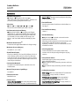
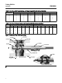
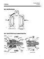
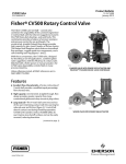
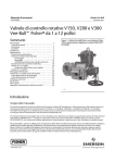
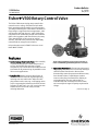
Product Bulletin V500 Valve 51.3:V500 May 2012 D100054X012 Fisherr V500 Rotary Control Valve The Fisher V500 eccentric plug rotary control valve controls erosive, coking, and other hard-to-handle fluids, providing either throttling or on-off operation. The flanged and flangeless valves feature streamlined flow passages, rugged metal trim components, and a self-centering seat ring (figures 1 and 2). With these components, the V500 rotary control valve combines globe valve ruggedness with the efficiency of a rotary valve. Matched with a Fisher power or manual actuator, the V500 rotary control valve dependably controls fluids in many process industries. Unless otherwise noted, all NACE references are to NACE MR0175-2002. Features Resists Damage from Erosive Flow–Valve assembly is specifically designed to combat the process of erosion. Streamlined flow passages, rugged components, and a wide choice of erosion-resistant trim materials all promote long, dependable service life in erosive applications. Long Seat Life–Path of eccentric plug (figure 4) minimizes contact with seat ring when opening, reducing seat wear and friction. When the valve plug rotates into the seat ring, a self-lapping action occurs, improving the fit between shut-off surfaces. Full-port, S31600, CoCr-A, or VTC seat ring has two shutoff surfaces and can be easily reversed, reducing downtime. www.Fisher.com W8380-2 Fisher V500 Flanged Rotary Control Valve with 1061 Ac tuator and FIELDVUEt DVC6200 Digital Valve Controller Operational Versatility–Self-centering seat ring and rugged plug allow forward or reverse flow with tight shutoff in either flow direction. Reverse flow direction helps move downstream turbulence away from shutoff surfaces. Full 90-degree rotation removes valve plug from flowstream, helping to reduce plug wear. Seat ring and retainer are available in full and restricted port constructions, and can easily be changed if capacity requirements change. (continued on page 3) Product Bulletin V500 Valve 51.3:V500 May 2012 D100054X012 Specifications Available Configuration J Flanged or J flangeless valve assembly (NPS 3 through 8 only) with reversible(1) metal or VTC (ceramic) seat ring and splined valve shaft Valve Sizes J NPS 1, J 1-1/2, J 2, J 3, J 4, J 6, and J 8 DN sizes are also available (see tables 1 and 2). End Connection Style and Rating J Raised-face flanges or J ring-type joint flanges (ASME B16.5). Valves with EN PN10 through PN100 flanges also available. Various flangeless valve sizes are available in certain ASME and EN ratings. (See tables 1 and 2 for ASME and EN availability by valve size.) erosive service Forward flow: Through seat ring and past valve plug; tends to open the valve Flow Coefficients See the section titled Coefficients in this bulletin, or Catalog 12 Flow Coefficient Ratio(3) 100 to 1 Actuator Mounting J Right-hand or J left-hand as viewed from the upstream side of the valve. Mounting position depends on the desired open valve plug position and flow direction required by operating conditions. For more information, see the Installation section. Maximum Inlet Pressure(2) Consistent with applicable ASME or EN flange ratings Maximum Pressure Drops(2) See tables 3, 4, 5, 6 and 7 Shutoff Classification Class IV per ANSI/FCI 70-2 and IEC 60534-4, (0.01% of valve capacity at full travel) for either flow direction. Leak rates for full and restricted port valves are based on full port valve capacities. Reduced port valves seat at the full port diameter. Valve Plug Rotation Counterclockwise to close (when viewed from actuator side of valve) through 90 degrees of plug rotation Valve/Actuator Action With diaphragm or piston rotary actuator, field-reversible between J push-down-to-close (extending actuator rod closes valve) and J push-down-to-open (extending actuator rod opens valve Construction Materials See table 8 for individual parts and table 9 for trim combinations Material Temperature Capability(2) See table 8 Packing Constructions PTFE V-Ring: With one carbon-filled PTFE conductive packing ring in single, double, or leak-off arrangements PTFE/Bound-Composition: With one graphited composition conductive packing ring in single, double, or leak-off arrangements Graphite Ribbon Packing Rings: In single, double, or leak-off arrangements Flow Characteristic Modified linear Flow Direction Reverse flow (standard): Past valve plug and through seat ring; tends to close the valve; recommended for (continued) 2 Product Bulletin V500 Valve 51.3:V500 May 2012 D100054X012 Specifications (continued) Shaft Diameters See figure 5 Dimensions and Approximate Weights See figure 5; face-to-face dimensions conform to ISA S75.04 and IEC 60534-3-2 Options J Restricted trim (retainer and seat ring) for low-flow applications, J sealed bearing constructions, J Line flange bolts (for flangeless valves), J Purged bearings; J ENVIRO-SEALt packing system; see figure 3 and bulletin 59.3:041, ENVIRO-SEAL Packing Systems for Rotary Valves (D101638X012) for more information 1. The reversible seat is not available in every trim material. Consult your Emerson Process Management sales office. 2. The pressure or temperature limits in the referenced tables or figures, and in any applicable code limitation, should not be exceeded. 3. Ratio of maximum flow coefficient to minimum usable flow coefficient. May also be called rangeability. Features (continued) Easy Installation–Integral valve body flanges mate with many different classes of pipeline flanges, satisfying a variety of piping requirements. Flanges help to eliminate exposed line flange bolting, shorten alignment and installation time, and promote secure valve installations and piping integrity. Flangeless valves are automatically self-centering on line bolting for easy installation. than the EPA (Environmental Protection Agency) limit of 100 ppm (parts per million). Sour Service Capability–Trim and bolting materials are available for applications handling sour service. These materials comply with the requirements of NACE MR0175-2002. Simple Assembly and Maintenance–No special orientation, precision clamping or repetitive centering of valve plug and seat ring is required when tightening the retainer, promoting accurate alignment and easy assembly. Rugged Construction–Durable, solid metal or VTC seat ring and valve plug shut off tightly without deforming plug arms or employing thin ball seals. Oversized shaft diameters and rugged trim parts allow high pressure drops. Improved Environmental Capabilities–The optional ENVIRO-SEAL packing systems are designed with very smooth shaft surfaces and live loading to provide improved sealing. The seal of the ENVIRO-SEAL system can restrict emissions to less Reliable Performance–Seat ring design (figure 2) self-centers, self-laps, and dynamically aligns with plug, giving excellent cycle life. Sealed metal bearings help prevent particle buildup and valve shaft seizure in erosive applications. Choice of Construction Materials–Plug, seat ring, and retainer are available in four levels of hardness for selection of erosion resistance. Contents Features . . . . . . . . . . . . . . . . . . . . . . . . . . . . . . . . . . . . . 1 Specifications . . . . . . . . . . . . . . . . . . . . . . . . . . . . . . . . 2 Installation . . . . . . . . . . . . . . . . . . . . . . . . . . . . . . . . . 13 Coefficients . . . . . . . . . . . . . . . . . . . . . . . . . . . . . . . . . 15 Tables Valve Size, Pressure Ratings, and Flange Compatibility . . . . . . . . . . . . . . . . . . . . . . . . . . . . . . 4 Maximum Allowable Shutoff Pressure Drops . . . . . . . . . . . . . . . . . . . . . . 6 Material Temperature Capabilities . . . . . . . . . . . . . . 11 Material Combinations . . . . . . . . . . . . . . . . . . . . . . . 12 Actuator Mounting Selections . . . . . . . . . . . . . . . . . 13 Dimensions . . . . . . . . . . . . . . . . . . . . . . . . . . . . . . . . . 14 3 Product Bulletin V500 Valve 51.3:V500 May 2012 D100054X012 Table 1. Valve Size, ASME Pressure Ratings, and Flange Compatibility (X indicates availability) FLANGED VALVE SIZE, NPS FLANGELESS CL150 CL300 CL600 CL150 CL300 CL600 X X X X X X X X X X X X X X X X X X X X X ------X X X X ------X X X X ------X X ----- 1 1-1/2 2 3 4 6 8 Table 2. Valve Size, EN Pressure Ratings, and Flange Capability (X indicates availability) Flanged Flangeless VALVE SIZE, DN PN 10 PN 16 PN 25 PN 40 PN 63 PN 100 PN 10 PN 16 PN 25 PN 40 PN 63 PN 100 25 40 50 80 100 150 200 X X X X X X X X X X X X X X X X X X X X X X X X X X X X X X X X X X X X X X X X X X ------X X X X ------X X X X ------X X X X ------X X X X ------X ------- --------------- Figure 1. Sectional of Fisher V500 Control Valve RETAINER VALVE PLUG SEAT RING FACE SEALS PACKING BEARING VALVE SHAFT 1 BEARING STOP O-RINGS TAPER AND EXPANSION PINS THRUST WASHER VALVE BODY W4170-3 1 W4172-2 DETAIL OF SEALED BEARINGS 1 4 END-TAPPED VALVE BODY AND PIPE PLUG OPTIONAL (LIMITED TO LESS THAN 232_C [450_F]) Product Bulletin V500 Valve 51.3:V500 May 2012 D100054X012 Figure 2. Detail of Seat Ring Design FACE SEAL SECTION FLOW DIRECTION FLOW DIRECTION 49A3685-C A3288-2 FORWARD FLOW SHUTOFF REVERSE FLOW SHUTOFF (STANDARD) Figure 3. Typical ENVIRO-SEAL Packing Arrangements for Rotary Valves PACKING BOX STUD SPRINGS VALVE BODY ACTUATOR MOUNTING YOKE ANTIEXTRUSION RINGS VALVE SHAFT VALVE SHAFT PACKING FLANGE PACKING BOX RING YOKE BEARING PACKING FLANGE PACKING BOX RING PTFE PACKING V-RINGS SHOWN PACKING FOLLOWER W5806-1 SINGLE PTFE PACKING SPRINGS PACKING FOLLOWER GRAPHITE PACKING SET W6125-1 GRAPHITE PACKING 5 Product Bulletin V500 Valve 51.3:V500 May 2012 D100054X012 Table 3. Maximum Allowable Shutoff Pressure Drops for Level 1 Trim, Bar VALVE BODY MATERIAL BEARING MATERIAL S44004 CoCr-A WCC steel PTFE/ compositionlined S31600 CoCr-A CF8M SST PTFE/ compositionlined S31600 VALVE BODY SIZE, NPS TEMPERATURE, _C 1 1-1/2 2 3 4 6 8 -29 to 149 68.9 55.2 41.4 41.4 41.4 41.4 24.1 149 to 204 68.9 55.2 41.4 41.4 41.4 41.4 23.8 204 to 316 68.9 55.2 41.4 41.4 41.4 41.4 23.1 -29 to 204 68.9 55.2 41.4 41.4 41.4 20.7 15.2 204 to 260 68.9 55.2 41.4 41.4 41.4 20.7 15.2 260 to 316 68.9 55.2 41.4 41.4 41.4 20.7 15.2 -29 to 93 68.9 55.2 41.4 41.4 41.4 41.4 93 to 149 68.9 55.2 41.4 41.4 41.4 41.4 149 to 204 68.9 55.2 41.4 41.4 41.4 41.4 204 to 260 68.9 55.2 41.4 41.4 41.4 41.4 23.1(2) 23.8(1) 22.1(2) 23.4(1) 21.7(2) -46 to 20 68.9 55.2 41.4 41.4 41.4 20.7 15.2 204 to 260 65.8 55.2 41.4 41.4 41.4 20.7 15.2 260 to 316 62.4 55.2 41.4 41.4 41.4 20.7 15.2 -46 to 93 68.9 55.2 41.4 41.4 41.4 41.4 93 to 149 68.9 55.2 41.4 41.4 41.4 41.4 149 to 204 68.9 55.2 41.4 41.4 41.4 41.4 204 to 260 65.8 55.2 41.4 41.4 41.4 41.4 1. S17400 shaft only 2. ASME SA-479 Grade S20910 SST shaft only. Pressure drops appropriate for both shaft materials. 6 24.1 24.1(1) 24.1 24.1(1) 23.1(2) 23.8(1) 22.1(2) 23.4(1) 21.7(2) Product Bulletin V500 Valve 51.3:V500 May 2012 D100054X012 Table 4. Maximum Allowable Shutoff Pressure Drops for Level 1 Trim, Psi VALVE BODY MATERIAL BEARING MATERIAL S44004 CoCr-A WCC steel PTFE/ compositionlined S31600 CoCr-A CF8M SST PTFE/ compositionlined S31600 VALVE BODY SIZE, NPS _F 1 1-1/2 2 3 4 6 8 -20 to 300 1000 800 600 600 600 600 350 300 to 400 1000 800 600 600 600 600 345 400 to 600 1000 800 600 600 600 600 335 -20 to 400 1000 800 600 600 600 300 220 400 to 500 1000 800 600 600 600 300 220 500 to 600 1000 800 600 600 600 300 220 -20 to 200 1000 800 600 600 600 600 200 to 300 1000 800 600 600 600 600 300 to 400 1000 800 600 600 600 600 400 to 500 1000 800 600 600 600 600 350 350(1) 335(2) 345(1) 320(2) 340(1) 315(2) -50 to 400 1000 800 600 600 600 300 220 400 to 500 955 800 600 600 600 300 220 500 to 600 905 800 600 600 600 300 220 -50 to 200 1000 800 600 600 600 600 200 to 300 1000 800 600 600 600 600 300 to 400 1000 800 600 600 600 600 400 to 500 955 800 600 600 600 600 350 350(1) 335(2) 345(1) 320(2) 340(1) 315(2) 1. S17400 shaft only 2. ASME SA-479 Grade S20910 SST shaft only. Pressure drops appropriate for both shaft materials. 7 Product Bulletin V500 Valve 51.3:V500 May 2012 D100054X012 Table 5. Maximum Allowable Shutoff Pressure Drops for Level 2 and 3 Trims, Bar VALVE BODY MATERIAL BEARING MATERIAL S44004 WCC steel CoCr-A PTFE/ compositionlined S31600 CoCr-A CF8M SST(3) PTFE/ compositionlined S31600 VALVE BODY SIZE, NPS TEMPERATURE, _C 1 1-1/2 2 3 4 6 8 -29 to 93 103.4 103.4 103.4 103.4 82.7 51.7 24.1 93 to 149 100.3 100.3 99.0 100.3 82.7 51.7 24.1 149 to 204 97.2 97.2 93.8 97.2 82.7 51.0 23.8 204 to 260 91.7 91.7 91.4 91.7 82.7 50.0 23.1 260 to 316 83.4 83.4 83.4 83.4 82.7 49.3 23.1 316 to 343 81.0 81.0 81.0 81.0 81.0 48.3 22.4 343 to 371 78.3 78.3 78.3 78.3 78.3 48.3 22.4 371 to 399 69.6 69.6 69.6 69.6 69.6 46.9 21.7 399 to 427 56.9 56.9 56.9 56.9 56.9 46.9 21.7 -29 to 204 68.9 55.2 41.4 41.4 41.4 20.7 15.2 204 to 260 68.9 55.2 41.4 41.4 41.4 20.7 15.2 260 to 316 68.9 55.2 41.4 41.4 41.4 20.7 15.2 316 to 343 68.9 55.2 41.4 41.4 41.4 20.7 15.2 343 to 371 68.9 55.2 41.4 41.4 41.4 20.7 15.2 371 to 399 68.9 55.2 41.4 41.4 41.4 20.7 15.2 399 to 427 56.9 55.2 41.4 41.4 41.4 20.7 15.2 -29 to 38 103.4 103.4 103.4 103.4 89.6 55.2 24.1 38 to 93 103.4 103.4 103.4 103.4 89.6 55.2 93 to 149 149 to 204 100.3 97.2 100.3 97.2 97.2 100.3 97.2 89.6 89.6 204 to 232 91.7 91.7 91.7 91.7 89.6 55.2 23.1(2) 54.8(1) 23.8(1) 51.0(2) 22.1(2) 53.8(1) 23.4(1) 50.0(2) 21.7(2) -46 to 204 68.9 55.2 41.4 41.4 41.4 20.7 15.2 204 to 260 65.8 55.2 41.4 41.4 41.4 20.7 15.2 260 to 316 62.4 55.2 41.4 41.4 41.4 20.7 15.2 316 to 343 61.4 55.2 41.4 41.4 41.4 20.7 15.2 343 to 371 59.6 55.2 41.4 41.4 41.4 20.7 15.2 371 to 399 58.3 55.2 41.4 41.4 41.4 20.7 15.2 399 to 427 57.2 55.2 41.4 41.4 41.4 20.7 15.2 -46 to 38 99.3 99.3 99.3 99.3 89.6 55.2 24.1 38 to 93 85.5 85.5 85.5 85.5 85.5 55.2 93 to 149 149 to 204 204 to 232 77.3 71.0 65.8 77.3 71.0 65.8 1. S17400 shaft only 2. ASME SA-479 Grade S20910 SST shaft only. Pressure drops appropriate for both shaft materials. 3. Level 3 trim is limited to a maximum temperature of 316_C. 8 100.3 24.1 24.1(1) 77.3 71.0 65.8 77.3 71.0 65.8 77.2 71.0 65.8 53.1 24.1 24.1(1) 23.1(2) 54.8(1) 23.8(1) 51.0(2) 22.1(2) 53.8(1) 23.4(1) 50.0(2) 21.7(2) Product Bulletin V500 Valve 51.3:V500 May 2012 D100054X012 Table 6. Maximum Allowable Shutoff Pressure Drops for Level 2 and 3 Trims, Psi VALVE BODY MATERIAL BEARING MATERIAL S44004 WCC steel CoCr-A PTFE/ compositionlined S31600 CoCr-A CF8M SST(3) PTFE/ compositionlined S31600 VALVE BODY SIZE, NPS TEMPERATURE, _F 1 1-1/2 2 3 4 6 8 -20 to 200 1500 1500 1500 1500 1200 750 350 200 to 300 1455 1455 1435 1455 1200 750 350 300 to 400 1410 1410 1360 1410 1200 740 345 400 to 500 1330 1330 1325 1330 1200 725 335 500 to 600 1210 1210 1210 1210 1200 715 335 600 to 650 1175 1175 1175 1175 1175 700 325 650 to 700 1135 1135 1135 1135 1135 700 325 700 to 750 1010 1010 1010 1010 1010 680 315 750 to 800 825 825 825 825 825 680 315 -20 to 400 1000 800 600 600 600 300 220 400 to 500 1000 800 600 600 600 300 220 500 to 600 1000 800 600 600 600 300 220 600 to 650 1000 800 600 600 600 300 220 650 to 700 1000 800 600 600 600 300 220 700 to 750 1000 800 600 600 600 300 220 750 to 800 825 800 600 600 600 300 220 -20 to 100 1500 1500 1500 1500 1300 800 350 100 to 200 1500 1500 1500 1500 1300 800 200 to 300 300 to 400 1455 1410 1455 1410 1455 1410 1455 1410 1300 1300 400 to 450 1330 1330 1330 1330 1330 800 350 350(1) 335(2) 795(1) 345(1) 740(2) 320(2) 780(1) 340(1) 725(2) 315(2) -50 to 400 1000 800 600 600 600 300 220 400 to 500 955 800 600 600 600 300 220 500 to 600 905 800 600 600 600 300 220 600 to 650 890 800 600 600 600 300 220 650 to 700 865 800 600 600 600 300 220 700 to 750 845 800 600 600 600 300 220 750 to 800 830 800 600 600 600 300 220 -50 to 100 1440 1440 1440 1440 1300 800 350 100 to 200 1240 1240 1240 1240 1240 800 200 to 300 300 to 400 400 to 450 1120 1030 955 1120 1030 955 1120 1030 955 1120 1030 955 1120 1030 955 770 350 350(1) 335(2) 795(1) 345(1) 740(2) 320(2) 780(1) 340(1) 725(2) 315(2) 1. S17400 shaft only 2. ASME SA-479 Grade S20910 SST shaft only. Pressure drops appropriate for both shaft materials. 3. Level 3 trim is limited to a maximum temperature of 600_F. 9 Product Bulletin V500 Valve 51.3:V500 May 2012 D100054X012 Table 7. Maximum Allowable Shutoff Pressure Drops for Level 4 Trim(1) VALVE BODY MATERIAL BEARING MATERIAL S44004 WCC steel CoCr-A CF8M SST VALVE BODY MATERIAL CoCr-A BEARING MATERIAL S44004 WCC steel CoCr-A CF8M SST CoCr-A BAR VALVE SIZE, NPS TEMPERATURE, _C 1 1-1/2 2 3 4 6 8 -29 to 93 103.4 103.4 70.3 103.4 78.6 52.4 24.1 93 to 149 100.3 100.3 70.3 100.3 78.6 52.4 24.1 149 to 204 97.2 97.2 70.3 97.2 78.6 51.0 23.8 204 to 260 91.7 91.7 70.3 91.7 78.6 50.0 23.1 260 to 316 83.4 83.4 70.3 83.4 78.6 49.3 23.1 316 to 371 78.3 78.3 70.3 78.3 78.3 48.3 22.4 371 to 427 56.9 56.9 56.9 56.9 56.9 46.9 21.7 -29 to 204 68.9 55.2 41.4 41.4 41.4 20.7 15.2 204 to 260 68.9 55.2 41.4 41.4 41.4 20.7 15.2 260 to 316 68.9 55.2 41.4 41.4 41.4 20.7 15.2 316 to 371 68.9 55.2 41.4 41.4 41.4 20.7 15.2 371 to 427 56.9 55.2 41.4 41.4 41.4 20.7 15.2 -46 to 204 68.9 55.2 41.4 41.4 41.4 20.7 15.2 204 to 260 65.8 55.2 41.4 41.4 41.4 20.7 15.2 260 to 316 62.4 55.2 41.4 41.4 41.4 20.7 15.2 316 to 371 59.6 55.2 41.4 41.4 41.4 20.7 15.2 371 to 427 57.2 55.2 41.4 41.4 41.4 20.7 15.2 TEMPERATURE, _F 1 1-1/2 2 3 4 6 8 -20 to 200 1500 1500 1020 1500 1140 750 350 200 to 300 1455 1455 1020 1455 1140 760 350 300 to 400 1410 1410 1020 1410 1140 740 345 400 to 500 1330 1330 1020 1330 1140 725 335 500 to 600 1210 1210 1020 1210 1140 715 335 600 to 700 1135 1135 1020 1135 1135 700 325 700 to 800 825 825 825 825 825 680 315 -20 to 400 1000 800 600 600 600 300 220 400 to 500 1000 800 600 600 600 300 220 500 to 600 1000 800 600 600 600 300 220 600 to 700 1000 800 600 600 600 300 220 700 to 800 825 800 600 600 600 300 220 -50 to 400 1000 800 600 600 600 300 220 400 to 500 955 800 600 600 600 300 220 500 to 600 905 800 600 600 600 300 220 600 to 700 855 800 600 600 600 300 220 700 to 800 830 800 600 600 600 300 220 1. VTC trim is incompatible with water and steam above 180_C (360_F). 10 PSI Product Bulletin V500 Valve 51.3:V500 May 2012 D100054X012 Table 8. Material Temperature Capabilities(1) PART NAME MINIMUM TO MAXIMUM TEMPERATURE MATERIAL _C _F Steel body S31600 retainer S31600 retainer with CoCr-A bore S31600 retainer with VTC bore -29 to 427 -20 to 800 CF8M body S31600 retainer S31600 retainer with CoCr-A bore S31600 retainer with VTC bore -198 to 538 -325 to 1000 Valve body and retainer NPS 1 and 1-1/2 S17400 retainer -29 to 427 -20 to 800 Solid CoCr-A retainer -29 to 427 -20 to 800 S31600 retainer -29 to 260 -20 to 500 CoCr-A retainer with VTC bore -29 to 427 -20 to 800 S31600 retainer -198 to 427 -325 to 800 WCC steel body Valve body and retainer NPS 2 through 8 CF8M body Solid CoCr-A retainer -46 to 324 -50 to 600 S31600 with CoCr-A bore -198 to 427 -325 to 800 CoCr-A retainer with VTC bore S31600 Seat ring -50 to 800 -325 to 1000 Solid CoCr-A -46 to 538 -50 to 1000 S31600 with CoCr-A seat -198 to 538 -325 to 1000 Solid VTC -46 to 427 -50 to 800 Chrome-plated S31600 -198 to 316 -325 to 600 Solid CoCr-A -46 to 538 -50 to 1000 S31600 with CoCr-A face (NPS 6 and 8 valves only) -198 to 538 -325 to 1000 Solid VTC (NPS 1 through 2 valves only) -46 to 427 -50 to 800 VTC surface bolted to an CoCr-A hub (NPS 3 through 8 valves only) -46 to 427 -50 to 800 Valve plug Valve shaft Taper and expansion pins -46 to 427 -198 to 538 S17400 -62 to 427 -80 to 800 S20910 -198 to 538 -325 to 1000 1 through 2-inch solid VTC valve plug N10276 -46 to 427 -50 to 800 Other valve plugs S20910 -198 to 538 -325 to 1000 PTFE/composition-lined S31600 -46 to 260 -50 to 500 Bearings CoCr-A(2) -198 to 538 -325 to 1000 S44004(2) -29 to 427 -20 to 800 O-rings(3) (for Alloy 6 or 440C SST Fluorocarbon -18 to 204 0 to 400 sealed bearings) Nitrile -29 to 93 -20 to 200 -325 to 1000 Bearing stop S31600 -198 to 538 S17700 for S17400 shaft -198 to 427 -325 to 800 R30016 for S20910 SST shaft -198 to 538 -325 to 1000 Face seals N07718 (NACE MR0175-2002 or PTFE/N10276 -198 to 538 -325 to 1000 Retainer gasket Graphite laminate for NPS 1 and 1-1/2 valves or S31600 for NPS 2 through 8 valves -198 to 538 -325 to 1000 PTFE -46 to 260 -50 to 500 Packing rings PTFE/bound composition -73 to 260 -100 to 500 Graphite ribbon -198 to 538 -325 to 1000 S31600 -198 to 538 -325 to 1000 SA-193-B7 studs and SA-194-2H nuts -46 to 427 -50 to 800 SA-193-B7M studs and SA-194-2HM nuts -29 to 427 -20 to 800 B8M studs and 8M nuts -198 to 538 -325 to 1000 S31600 -198 to 538 -325 to 1000 Thrust washer Packing follower Studs and nuts Packing box ring 1. VTC trim is incompatible with water and steam above 180_C (360_F). 2. Recommended for erosive applications. 3. For sealed bearing constructions 11 Product Bulletin V500 Valve 51.3:V500 May 2012 D100054X012 Table 9. Material Combinations(1) Trim Level 1 Plug Chrome-plated S31600 (NPS 1 thru 8 valves) Seat Ring S31600 Retainer S17400 (WCC only), or S31600 Valve Shaft S17400 Grade S20910 Bearing O-Ring PTFE/composition-lined S31600 --- CoCr-A --- S44004 --- PTFE/composition-lined S31600 --- CoCr-A --- PTFE/composition-lined S31600 --- CoCr-A Nitrile --- 2 Solid CoCr-A (NPS 1 thru 4 valves) and S31600 with CoCr-A face (NPS 6 and 8 valves) Solid CoCr-A (NPS 1 thru 4 valves) and S31600 with CoCr-A seat (NPS 6 and 8 valves) S17400 Body Both WCC Both Both Fluorocarbon --- S17400 (WCC only), or S31600 S44004 Nitrile WCC Fluorocarbon Grade S20910 PTFE/composition-lined S31600 --- CoCr-A Nitrile --- Both Fluorocarbon PTFE/composition-lined S31600 --- CoCr-A Nitrile --- 3 Solid CoCr-A (NPS 1 thru 8 valves) Solid CoCr-A S31600 with CoCr-A sleeve bore (NPS 1 and 1-1/2) Solid CoCr-A (NPS 2 thru 6) S17400 Both Fluorocarbon --S44004 Nitrile WCC Fluorocarbon Grade S20910 PTFE/composition-lined S31600 --- CoCr-A Nitrile --- Both Fluorocarbon 4(2) Solid VTC (NPS 1 thru 2 valves) VTC plug surface bolted to CoCr-A hub, titanium grade 5 cap screw, and S31600 gasket (NPS 3 through 8 valves) Solid VTC S31600 with VTC bore (NPS 1 and 1-1/2 valves) Solid CoCr-A retainer with VTC bore (NPS 2 thru 8 valves) PTFE/composition-lined S31600 --- CoCr-A Nitrile --- S17400 Fluorocarbon --S44004 Nitrile WCC Fluorocarbon Grade S20910 PTFE/composition-lined S31600 --- CoCr-A Nitrile --Fluorocarbon 1. NACE MR0175-2002 trim constructions are available; consult your Emerson Process Management sales office. 2. VTC trim is incompatible with water and steam above 180_C (360_F). 12 Both Both Product Bulletin V500 Valve 51.3:V500 May 2012 D100054X012 Table 10. Actuator Mounting Selections, with Action and Open Plug Position Options MOUNTING Left-hand Right-hand ACTION(1) OPEN PLUG POSITION Forward Flow Reverse Flow PDTC Below shaft Above shaft PDTO Below shaft Above shaft PDTC Above shaft Below shaft PDTO Above shaft Below shaft Actuator and Accessory Information Refer to the specific actuator and accessory bulletins for required ordering information. Figure 4. Eccentric Rotation 1. PDTC–Push-down-to-close (extending actuator rod closes valve) PDTO–Push-down-to open (extending actuator rod opens valve). VALVE BODY CENTERLINE Installation VALVE SHAFT CENTERLINE The V500 control valve may be installed in any position. However, for best shutoff performance, a position with the shaft horizontal is recommended. The control valve may be installed in forward or reverse flow direction. Forward flow (through the seat ring and past the plug) tends to open the valve; reverse flow (past the plug and through the seat ring) tends to close the valve. The reverse flow direction is recommended for erosive applications. VALVE BODY CENTERLINE Specific operating conditions may require a specific combination of push-down-to-close or -open actuator motion and open valve plug position above or below the shaft. To satisfy specific operating requirements, the complete control valve package (valve and actuator) can be assembled and installed in different ways, providing eight options for actuator motion and open plug position. VALVE SHAFT CENTERLINE Table 10 and the appropriate actuator bulletin describe possible assembly and installation options. For assistance in selecting the appropriate combination of actuator action and open valve position, consult your Emerson Process Management sales office. VALVE BODY CENTERLINE VALVE SHAFT CENTERLINE Dimensions are shown in figure 5. Valve Information To determine the required valve ordering information, refer to the Specifications table. Review the information under each specification and in the referenced tables. B1879-1 The Size 20 Fisher 1052 actuator is not available for use with V500 rotary control valves because the sizing of this combination is marginal. 13 Product Bulletin V500 Valve 51.3:V500 May 2012 D100054X012 Table 11. Fisher V500 Rotary Control Flanged and Flangeless Valve Dimensions VALVE SIZE, NPS DIMENSIONS A RF B RTJ RF RTJ D K APPROXIMATE WEIGHT S (SHAFT DIA)(1) T U W Flanged Flangeless Pressure Class Pressure Class CL150 CL300 CL600 CL150 CL300 CL600 mm kg 1 102 108 51 57 187 126 12.7 118 --- 11 5.4 5.9 5.9 --- --- --- 1-1/2 114 122 57 63 187 135 15.9 118 --- 14 8.6 9.5 10 --- --- --- 2 124 124 62 62 187 151 15.9 118 --- 14 9.5 11 13 --- --- --- 152 32 14 19 24 26 16 16 16 235 46 18 36 42 50 34 34 34 54 69 93 50 50 --- 79 98 135 57 68 --- 3 165 165 83 83 213 200 25.4 25.4 x 19.1 4 194 194 97 97 208 216 31.8 235 46 5/8-Inch 11 UNC 235 46 5/8-Inch 11 UNC 6 229 229 114 114 208 270 38.1 38.1 x 31.8 8 243 243 121 121 208 318 38.1 VALVE SIZE, NPS Inches Pounds 1 4.00 4.25 2.00 2.25 7.38 4.97 1/2 4.62 --- 0.45 12 13 13 --- --- --- 1-1/2 4.50 4.75 2.25 2.50 7.38 5.31 5/8 4.62 --- 0.56 19 21 23 --- --- --- 2 4.88 4.88 2.44 2.44 7.38 5.94 5/8 4.62 --- 0.56 21 25 28 --- --- --- 6.00 1.25 0.56 42 52 57 35 35 35 9.25 1.81 0.69 79 93 111 75 75 75 120 152 204 110 110 --- 175 217 298 125 150 --- 3 6.50 6.50 3.25 3.25 8.44 7.88 1 1 x 3/4 4 7.62 7.62 3.81 3.81 8.19 8.50 1-1/4 9.25 1.81 5/8-Inch 11 UNC 9.25 1.81 5/8-Inch 11 UNC 6 9.00 9.00 4.50 4.50 8.19 10.6 1-1/2 1-1/2 x 1-1/4 8 9.56 9.56 4.78 4.78 8.19 12.5 1-1/2 1. Shaft diameter versus spline diameter. Figure 5. Fisher V500 Rotary Control Flanged and Flangeless Valve Dimensions (refer to table 11) CL150, CL300, OR CL600 FLANGELESS OR WITH RF OR RTJ FLANGES NPS 1, 1-1/2 AND 2 BODY MOUNTING NPS 3 AND 4 BODY MOUNTING A3289-1 NOTE: FOR DIMENSIONS OF VALVES WITH DIN (OR OTHER) END CONNECTIONS, CONSULT YOUR EMERSON PROCESS MANAGEMENT SALES OFFICE. 14 NPS 6 AND 8 BODY MOUNTING Product Bulletin V500 Valve 51.3:V500 May 2012 D100054X012 Coefficients Table 12. Fisher V500, Forward Flow, Level 1, 2 and 3 Trims Full Port Coefficients Valve Size, NPS Modified Linear Characteristic Valve Rotation, Degrees 10 20 30 40 50 60 70 80 90 1.22 2.89 5.05 7.63 9.94 11.3 11.8 12.0 12.2 1.06 2.50 4.37 6.60 8.60 9.77 10.2 10.4 10.6 0.49 0.64 0.73 0.81 0.87 0.92 0.96 0.99 1.00 FL 0.89 0.89 0.88 0.85 0.85 0.85 0.85 0.85 0.85 XT 0.480 0.497 0.508 0.548 0.597 0.632 0.636 0.612 0.593 Cv 2.07 6.15 11.5 16.6 20.7 23.5 25.3 26.1 26.6 Kv 1.79 5.32 9.95 14.4 17.9 20.3 21.9 22.6 23.0 0.48 0.63 0.73 0.81 0.87 0.92 0.96 0.99 1.00 FL 0.95 0.85 0.85 0.84 0.84 0.84 0.84 0.84 0.84 XT 0.770 0.476 0.483 0.555 0.616 0.636 0.632 0.601 0.589 Cv 4.11 8.73 16.7 27.0 37.2 43.4 45.8 46.2 46.2 Kv 3.56 7.55 14.4 23.4 32.2 37.5 39.6 40.0 40.0 0.49 0.63 0.73 0.81 0.87 0.92 0.96 0.99 1.00 FL 0.97 0.92 0.84 0.79 0.77 0.75 0.75 0.74 0.74 XT 0.439 0.442 0.442 0.422 0.422 0.462 0.452 0.442 0.442 Cv 8.80 22.7 43.3 71.3 96.8 116 130 138 142 Kv 7.61 19.6 37.5 61.7 83.7 100 112 119 123 Fd 0.46 0.62 0.73 0.81 0.87 0.92 0.96 0.99 1.00 Cv Kv Fd Fd Fd 1 1-1/2 2 3 FL 0.86 0.84 0.83 0.83 0.83 0.82 0.78 0.77 0.77 XT 0.469 0.544 0.574 0.526 0.497 0.526 0.508 0.476 0.456 Cv 16.6 41.3 79.1 123 166 203 230 247 255 Kv 14.3 35.7 68.4 106 144 176 199 214 221 0.45 0.61 0.72 0.81 0.87 0.92 0.96 0.99 1.00 Fd 4 FL 0.85 0.82 0.81 0.81 0.80 0.79 0.77 0.76 0.76 XT 0.439 0.555 0.501 0.466 0.473 0.490 0.480 0.459 0.442 Cv 17.5 79.1 155 270 363 434 492 540 565 Kv 15.1 68.4 134 234 314 375 426 467 489 0.44 0.60 0.72 0.81 0.87 0.92 0.96 0.99 1.00 Fd 6 FL 0.97 0.93 0.88 0.82 0.76 0.73 0.72 0.71 0.71 XT 0.879 0.585 0.540 0.456 0.439 0.432 0.436 0.426 0.416 Cv 51.5 146 298 481 646 775 879 981 1050 Kv 44.5 126 258 416 559 670 760 849 908 0.43 0.59 0.72 0.80 0.87 0.92 0.96 0.99 1.00 Fd 8 FL 0.97 0.93 0.87 0.78 0.72 0.71 0.70 0.69 0.67 XT 0.456 0.605 0.533 0.449 0.413 0.403 0.391 0.372 0.360 15 Product Bulletin V500 Valve 51.3:V500 May 2012 D100054X012 Table 13. Fisher V500, Reverse Flow, Level 1, 2, and 3 Trims Full Port Coefficients Valve Rotation, Degrees Modified Linear Characteristic 80 90 10 20 30 40 50 60 70 Cv 1.08 2.82 5.26 9.11 12.4 14.7 15.9 16.4 16.8 Kv 0.93 2.44 4.55 7.88 10.7 12.7 13.8 14.2 14.5 Fd 0.49 0.64 0.73 0.81 0.87 0.92 0.96 0.99 1.00 FL 0.80 0.79 0.73 0.63 0.58 0.55 0.56 0.51 0.48 XT 0.172 0.284 0.406 0.357 0.345 0.322 0.300 0.289 0.283 Cv 1.71 5.33 11.3 18.4 24.7 28.6 30.1 30.7 31.0 Kv 1.48 4.61 9.77 15.9 21.4 24.7 26.0 26.6 26.8 Fd 1 0.48 0.63 0.73 0.81 0.87 0.92 0.96 0.99 1.00 FL 0.75 0.74 0.70 0.66 0.64 0.63 0.63 0.63 0.63 XT 0.357 0.442 0.432 0.397 0.369 0.360 0.360 0.357 0.357 Cv 2.98 7.40 15.6 27.6 41.9 52.9 56.4 57.2 57.4 Kv 2.58 6.40 13.5 23.9 36.2 45.8 48.8 49.5 49.7 Fd 1-1/2 0.49 0.63 0.73 0.81 0.87 0.92 0.96 0.99 1.00 FL 0.92 0.89 0.81 0.67 0.60 0.58 0.58 0.58 0.58 XT 0.480 0.476 0.462 0.384 0.308 0.265 0.265 0.265 0.265 Cv 7.19 21.4 47.0 75.4 105 122 132 134 141 Kv 6.22 18.5 40.7 65.2 90.8 106 114 116 122 Fd 2 0.46 0.62 0.73 0.81 0.87 0.92 0.96 0.99 1.00 FL 0.80 0.80 0.77 0.71 0.66 0.65 0.65 0.65 0.65 XT 0.357 0.476 0.487 0.436 0.372 0.378 0.384 0.376 0.357 Cv 12.2 39.0 79.9 124 171 202 222 232 235 Kv 10.6 33.7 69.1 107 148 175 192 201 203 Fd 3 0.45 0.61 0.72 0.81 0.87 0.92 0.96 0.99 1.00 FL 0.90 0.89 0.81 0.73 0.71 0.70 0.69 0.69 0.69 XT 0.522 0.544 0.487 0.456 0.406 0.406 0.416 0.423 0.416 Cv 15.1 72.4 156 251 351 438 534 638 717 Kv 13.1 62.6 135 217 304 379 462 552 620 Fd 4 0.44 0.60 0.72 0.81 0.87 0.92 0.96 0.99 1.00 FL 0.85 0.85 0.82 0.77 0.70 0.66 0.61 0.57 0.51 XT 0.416 0.597 0.518 0.522 0.452 0.388 0.336 0.270 0.219 Cv 33.5 143 302 485 663 798 871 897 986 Kv 29.0 124 261 420 573 690 753 776 853 Fd 16 Valve Size, NPS 6 0.43 0.59 0.72 0.80 0.87 0.92 0.96 0.99 1.00 FL 0.81 0.81 0.79 0.76 0.68 0.66 0.66 0.66 0.66 XT 0.697 0.593 0.483 0.410 0.354 0.342 0.366 0.403 0.363 8 Product Bulletin V500 Valve 51.3:V500 May 2012 D100054X012 Table 14. Fisher V500, Forward Flow, Level 1, 2, and 3 Trims Reduced Port Coefficients Valve Size, NPS Valve Rotation, Degrees Modified Linear Characteristic 80 90 10 20 30 40 50 60 70 Cv 0.777 2.09 3.02 3.62 4.53 4.90 4.93 4.96 5.01 Kv 0.672 1.81 2.61 3.13 3.92 4.24 4.26 4.29 4.33 Fd (1) 0.54 0.66 0.75 0.82 0.88 0.92 0.96 0.99 1.00 FL 0.89 0.89 0.88 0.85 0.82 0.79 0.75 0.74 0.74 XT 0.487 0.391 0.497 0.597 0.508 0.439 0.436 0.429 0.419 Cv 0.632 2.56 4.47 7.15 9.62 10.7 10.8 10.9 10.9 Kv .547 2.21 3.87 6.18 8.32 9.26 9.34 9.43 9.43 Fd (1) 1 0.53 0.66 0.75 0.82 0.88 0.92 0.96 0.99 1.00 FL 0.84 0.84 0.84 0.82 0.79 0.75 0.73 0.73 0.73 XT 0.559 0.397 0.522 0.574 0.585 0.508 0.497 0.490 0.490 Cv 1.30 3.49 5.31 9.64 15.1 17.3 17.3 17.3 17.3 Kv 1.12 3.02 4.59 8.34 13.1 15.0 15.0 15.0 15.0 Fd (1) 1-1/2 0.54 0.66 0.75 0.82 0.88 0.92 0.96 0.99 1.00 FL 0.85 0.85 0.84 0.84 0.82 0.79 0.79 0.79 0.79 XT 0.391 0.336 0.452 0.563 0.529 0.462 0.462 0.462 0.462 Cv 6.78 11.5 16.0 26.7 40.2 47.7 48.4 48.4 48.4 Kv 5.86 9.95 13.8 23.1 34.8 41.3 41.9 41.9 41.9 Fd (1) 2 0.53 0.66 0.75 0.82 0.88 0.92 0.96 0.99 1.00 FL 0.90 0.88 0.87 0.86 0.85 0.82 0.77 0.77 0.77 XT 0.487 0.501 0.487 0.429 0.459 0.429 0.429 0.429 0.429 Cv 10.0 18.2 24.4 43.7 69.2 90.6 98.2 98.2 98.2 Kv 8.65 15.7 21.1 37.8 59.9 78.4 84.9 84.9 84.9 Fd (1) 3 0.52 0.65 0.74 0.82 0.88 0.92 0.96 0.99 1.00 FL 0.95 0.89 0.85 0.84 0.84 0.81 0.77 0.77 0.77 XT 0.426 0.459 0.570 0.504 0.487 0.462 0.426 0.426 0.426 Cv 9.50 26.6 41.8 76.0 129 170 200 200 200 Kv 8.22 23.0 36.2 65.7 112 147 173 173 173 Fd (1) 4 0.52 0.65 0.74 0.82 0.88 0.92 0.96 0.99 1.00 FL 0.97 0.96 0.92 0.86 0.80 0.76 0.74 0.74 0.74 XT 0.995 0.351 0.403 0.487 0.416 0.462 0.410 0.410 0.410 Cv 39.9 87.8 155 241 343 448 541 606 623 Kv 34.5 75.9 134 208 297 388 468 524 539 Fd (2) 6 0.48 0.63 0.73 0.81 0.87 0.92 0.96 0.99 1.00 FL 0.96 0.81 0.80 0.79 0.78 0.76 0.74 0.72 0.70 XT 0.400 0.446 0.459 0.449 0.429 0.413 0.413 0.413 0.391 8 1. Measured at 60% Port. 2. Measured at 40% Port. 17 Product Bulletin V500 Valve 51.3:V500 May 2012 D100054X012 Table 15. Fisher V500, Reverse Flow, Level 1, 2, and 3 Reduced Port Coefficients Modified Linear Characteristic Valve Rotation, Degrees 10 20 30 40 50 60 70 80 90 Cv .634 2.09 3.34 3.96 5.21 5.64 5.70 5.71 5.76 Kv .548 1.81 2.89 3.43 4.51 4.88 4.93 4.94 4.98 0.54 0.66 0.75 0.82 0.88 0.92 0.96 0.99 1.00 FL 0.70 0.70 0.70 0.70 0.70 0.70 0.70 0.70 0.70 XT 0.230 0.216 0.207 0.406 0.366 0.348 0.339 0.345 0.342 Cv .464 1.93 4.21 7.81 11.0 12.1 12.1 12.2 12.2 Kv .401 1.67 3.64 6.76 9.52 10.5 10.5 10.6 10.6 0.53 0.66 0.75 0.82 0.88 0.92 0.96 0.99 1.00 FL 0.93 0.93 0.75 0.72 0.70 0.70 0.70 0.70 0.70 XT 0.970 0.416 0.501 0.467 0.416 0.416 0.416 0.413 0.416 Cv .965 2.68 4.82 12.0 17.7 18.7 18.8 18.9 18.9 Kv .835 2.31 4.17 10.4 15.3 16.2 16.3 16.3 16.3 0.54 0.66 0.75 0.82 0.88 0.92 0.96 0.99 1.00 FL 0.96 0.96 0.77 0.67 0.62 0.62 0.62 0.62 0.62 XT 0.518 0.508 0.559 0.354 0.351 0.360 0.357 0.354 0.354 Cv 5.95 10.6 14.7 29.9 49.0 56.0 56.2 56.2 56.7 Kv 5.15 9.17 12.7 25.9 42.4 48.4 48.6 48.6 49.0 0.53 0.66 0.75 0.82 0.88 0.92 0.96 0.99 1.00 FL 0.80 0.79 0.73 0.64 0.59 0.58 0.58 0.58 0.58 XT 0.429 0.455 0.487 0.345 0.286 0.286 0.286 0.286 0.281 Cv 7.69 15.3 22.7 42.6 75.0 98.0 99.5 100 102 Kv 6.65 13.2 19.6 36.8 64.9 84.8 86.1 86.5 88.2 1.00 Fd(1) Fd(1) Fd(1) Fd(1) Fd(1) 1 1-1/2 2 3 0.52 0.65 0.74 0.82 0.88 0.92 0.96 0.99 FL 0.83 0.82 0.81 0.77 0.60 0.59 0.58 0.58 0.58 XT 0.504 0.548 0.555 0.529 0.375 0.322 0.336 0.334 0.319 Cv 5.10 20.6 34.6 71.9 123 170 230 231 232 Kv 4.41 17.8 29.9 62.2 106 147 199 200 201 0.52 0.65 0.74 0.82 0.88 0.92 0.96 0.99 1.00 Fd(1) 4 6 FL 0.97 0.95 0.90 0.82 0.73 0.65 0.57 0.55 0.55 XT 0.990 0.551 0.566 0.533 0.432 0.397 0.263 0.260 0.258 Cv 27.1 74.3 140 232 342 457 552 614 646 Kv 23.4 64.3 121 201 296 395 477 531 559 0.48 0.63 0.73 0.81 0.87 0.92 0.96 0.99 1.00 Fd(2) 8 FL 0.92 0.91 0.88 0.76 0.69 0.66 0.62 0.60 0.58 XT 0.636 0.494 0.494 0.490 0.442 0.388 0.369 0.339 0.311 1. Measured at 60% Port. 2. Measured at 40% Port. 18 Valve Size, NPS Product Bulletin V500 Valve 51.3:V500 May 2012 D100054X012 Table 16. Fisher V500, Forward Flow, Level 4 Trim Full Port Coefficients Valve Size, NPS Valve Rotation, Degrees Modified Linear Characteristic 80 90 10 20 30 40 50 60 70 Cv .30 1.91 4.68 7.3 9.17 10.3 11.0 11.5 11.6 Kv .260 1.65 4.05 6.31 7.93 8.91 9.52 9.95 10.0 Fd 0.49 0.64 0.73 0.81 0.87 0.92 0.96 0.99 1.00 FL --- 0.98 0.87 0.87 0.85 0.86 0.85 0.86 0.84 XT 0.668 0.574 0.529 0.566 0.616 0.668 0.685 0.628 0.616 Cv 1.46 3.79 8.13 13.4 17.9 20.7 22.4 24.0 25.0 Kv 1.26 3.28 7.03 11.6 15.5 17.9 19.4 20.8 21.6 Fd 1 0.48 0.63 0.73 0.81 0.87 0.92 0.96 0.99 1.00 FL 0.86 0.86 0.82 0.84 0.80 0.80 0.79 0.79 0.79 XT 0.566 0.605 0.55 0.544 0.551 0.574 0.589 0.585 0.597 Cv 1.76 6.0 13.8 22.6 29.5 35.2 38.4 38.4 38.4 Kv 1.52 5.19 11.9 19.5 25.5 30.4 33.2 33.2 33.2 Fd 1-1/2 0.49 0.63 0.73 0.81 0.87 0.92 0.96 0.99 1.00 FL 0.95 0.96 0.94 0.83 0.81 0.80 0.77 0.77 0.78 XT 0.819 0.555 0.501 0.480 0.533 0.566 0.570 0.585 0.585 Cv 7.6 23.2 44.0 62.6 82.5 102 115 119 124 Kv 6.57 20.1 38.1 54.1 71.4 88.2 99.5 103 107 Fd 2 0.46 0.62 0.73 0.81 0.87 0.92 0.96 0.99 1.00 FL 0.88 0.87 0.85 0.84 0.83 0.82 0.80 0.80 0.80 3 XT 0.578 0.494 0.511 0.540 0.529 0.515 0.518 0.533 0.526 CV 9.31 37.0 73.5 111 144 171 192 208 221 KV 8.05 32.0 63.6 96.0 125 148 166 180 191 Fd 0.45 0.61 0.72 0.81 0.87 0.92 0.96 0.99 1.00 FL 0.94 0.90 0.85 0.84 0.82 0.80 0.77 0.77 0.77 XT 0.526 0.476 0.449 0.452 0.480 0.504 0.511 0.501 0.487 Cv 9.71 64.3 141 222 299 368 426 469 499 Kv 8.40 55.6 122 192 259 318 368 406 432 Fd 4 0.44 0.60 0.72 0.81 0.87 0.92 0.96 0.99 1.00 FL 0.95 0.88 0.82 0.80 0.78 0.78 0.77 0.77 0.76 XT 0.504 0.459 0.432 0.422 0.429 0.436 0.432 0.422 0.413 Cv 34.6 142 290 447 592 716 822 911 958 Kv 29.9 123 251 387 512 619 711 788 829 Fd 6 0.43 0.59 0.72 0.80 0.87 0.92 0.96 0.99 1.00 FL 0.92 0.76 0.78 0.79 0.77 0.76 0.73 0.71 0.73 XT 0.544 0.446 0.426 0.429 0.429 0.46 0.419 0.410 0.429 8 19 Product Bulletin V500 Valve 51.3:V500 May 2012 D100054X012 Table 17. Fisher V500, Reverse Flow, Level 4 Trim Full Port Coefficients Modified Linear Characteristic Valve Rotation, Degrees 10 20 30 40 50 60 70 80 90 Cv .107 1.85 Kv .093 1.60 5.09 8.8 11.9 13.6 14.0 14.0 15.3 4.40 7.61 10.3 11.8 12.1 12.1 0.49 13.2 0.64 0.73 0.81 0.87 0.92 0.96 0.99 FL 1.00 --- 0.88 0.65 0.60 0.54 0.54 0.60 0.62 0.61 XT 0.334 0.526 0.426 0.360 0.334 0.345 0.372 0.384 0.334 Cv .988 3.37 7.66 13.5 19.3 23.5 25.3 25.3 26.1 Kv .854 2.92 6.63 11.7 16.7 20.3 21.9 21.9 22.6 0.48 0.63 0.73 0.81 0.87 0.92 0.96 0.99 1.00 FL 0.98 0.92 0.75 0.73 0.62 0.58 0.59 0.61 0.61 XT 0.473 0.585 0.563 0.487 0.432 0.403 0.400 0.426 0.429 Cv 1.42 4.92 11.8 20.9 29.8 36.7 40.9 42.7 43.0 Kv 1.23 4.26 10.2 18.1 25.8 31.7 35.4 36.9 37.2 0.49 0.63 0.73 0.81 0.87 0.92 0.96 0.99 1.00 FL 0.97 0.93 0.86 0.77 0.72 0.62 0.64 0.63 0.66 XT 0.403 0.718 0.616 0.518 0.473 0.452 0.452 0.446 0.439 Cv 7.64 20.6 41.3 62.4 80.5 94.8 105 109 111 Kv 6.61 17.8 34.9 54.0 69.6 82.0 90.8 94.3 96.0 1.00 Fd Fd Fd Fd 1 1-1/2 2 0.46 0.62 0.73 0.81 0.87 0.92 0.96 0.99 FL 0.93 0.91 0.89 0.81 0.73 0.72 0.71 0.74 0.76 XT 0.616 0.656 0.537 0.497 0.501 0.508 0.504 0.515 0.511 Cv 8.07 31.3 67.1 102 129 153 174 189 192 Kv 6.98 27.1 58.0 88.2 112 132 151 163 166 0.45 0.61 0.72 0.81 0.87 0.92 0.96 0.99 1.00 Fd 3 4 FL 0.86 0.85 0.84 0.80 0.75 0.75 0.75 0.75 0.74 XT 0.456 0.664 0.533 0.490 0.515 0.526 0.522 0.504 0.515 Cv 10.5 58.6 134 218 294 356 406 445 461 Kv 9.08 50.7 116 189 254 308 351 385 399 0.44 0.60 0.72 0.81 0.87 0.92 0.96 0.99 1.00 Fd 6 FL 0.80 0.76 0.72 0.70 0.68 0.69 0.69 0.69 0.69 XT 0.511 0.551 0.459 0.406 0.391 0.397 0.410 0.416 0.429 Cv 25.4 136 266 413 554 686 818 895 897 Kv 22.0 118 230 357 479 593 708 774 776 0.43 0.59 0.72 0.80 0.87 0.92 0.96 0.99 1.00 Fd 20 Valve Size, NPS 8 FL 0.75 0.77 0.75 0.72 0.73 0.69 0.70 0.70 0.72 XT 0.731 0.439 0.483 0.469 0.439 0.397 0.360 0.375 0.426 Product Bulletin V500 Valve 51.3:V500 May 2012 D100054X012 Table 18. Fisher V500 Forward Flow, Level 4 Trim Reduced Port Coefficients Valve Size, NPS Modified Linear Characteristic Valve Rotation, Degrees 10 20 30 40 50 60 70 80 90 Cv 2.14 3.70 4.65 5.25 5.50 5.57 5.66 5.66 5.66 Kv 1.84 3.18 4.00 4.52 4.73 4.79 4.87 4.87 4.87 0.54 0.66 0.75 0.82 0.88 0.92 0.96 0.99 1.00 FL 0.64 0.75 0.75 0.79 0.75 0.74 0.73 0.73 0.73 XT 0.286 0.388 0.464 0.483 0.471 0.459 0.444 0.444 0.444 Cv 2.10 4.55 6.16 8.00 10.4 11.3 11.3 11.3 11.3 Kv 1.81 3.91 5.30 6.88 8.94 9.72 9.72 9.72 9.72 0.53 0.66 0.75 0.82 0.88 0.92 0.96 0.99 1.00 FL 0.82 0.79 ²0.79 0.79 0.79 0.72 0.72 0.72 0.72 XT 0.469 0.397 0.454 0.500 0.502 0.482 0.482 0.482 0.482 Cv 2.75 5.15 6.70 9.65 13.7 16.8 18.8 18.8 17.9 Kv 2.37 4.43 5.76 8.30 11.8 14.5 16.2 16.2 15.4 0.54 0.66 0.75 0.82 0.88 0.92 0.96 0.99 1.00 FL 0.75 0.76 0.83 ²0.86 0.87 0.85 0.77 0.77 0.81 XT 0.467 0.448 0.519 0.624 0.612 0.543 0.444 0.439 0.484 Cv 4.12 9.50 13.1 19.8 29.6 39.0 45.3 48.0 48.0 Kv 3.56 8.22 11.3 17.1 25.6 33.7 39.2 41.5 41.5 0.53 0.66 0.75 0.82 0.88 0.92 0.96 0.99 1.00 FL 0.80 0.80 0.88 0.86 0.84 0.82 0.81 0.79 0.77 XT 0.469 0.551 0.605 0.522 0.518 0.551 0.515 0.466 0.466 Cv 2.26 11.2 20.1 33.3 50.8 69.1 83.0 89.3 90.1 Kv 1.95 9.69 17.4 28.8 43.9 59.8 71.8 77.2 77.9 0.52 0.65 0.74 0.82 0.88 0.92 0.96 0.99 1.00 FL 0.96 0.95 0.85 0.86 0.86 0.83 0.80 0.77 0.74 XT 0.779 0.779 0.632 0.620 0.612 0.589 0.537 0.466 0.452 Cv 13.6 37.9 49.8 82.9 122 159 184 194 196 Kv 11.8 32.8 43.1 71.7 106 138 159 168 170 0.52 0.65 0.74 0.82 0.88 0.92 0.96 0.99 1.00 Fd(1) Fd(1) Fd(1) Fd(1) Fd(1) Fd(1) 1 1-1/2 2 3 4 6 FL 0.97 0.69 0.72 0.74 0.77 0.81 0.81 0.77 0.77 XT 0.518 0.280 0.381 0.357 0.397 0.452 0.476 0.452 0.442 Cv 19.7 63.6 134 228 334 438 526 587 605 Kv 17.0 55.0 116 197 289 379 455 508 523 0.48 0.63 0.73 0.81 0.87 0.92 0.96 0.99 1.00 Fd(2) 8 FL 0.93 0.83 0.76 0.77 0.77 0.77 0.75 0.75 0.72 XT 0.597 0.473 0.422 0.394 0.378 0.381 0.400 0.429 0.436 1. Measured at 60% Port. 2. Measured at 40% Port. 21 Product Bulletin V500 Valve 51.3:V500 May 2012 D100054X012 Table 19. Fisher V500 Reverse Flow, Level 4 Trim Reduced Port Coefficients Modified Linear Characteristic Valve Rotation, Degrees 10 20 30 40 50 60 70 80 90 Cv 1.90 3.80 4.85 5.82 5.90 5.90 5.90 5.90 5.90 Kv 1.63 3.27 4.17 5.01 5.07 5.07 5.07 5.07 5.07 0.54 0.66 0.75 0.82 0.88 0.92 0.96 0.99 1.00 FL 0.56 0.67 0.68 0.69 0.73 0.75 0.75 0.75 0.75 XT 0.312 0.386 0.427 0.409 0.448 0.448 0.448 0.448 0.448 Cv 1.95 4.45 5.75 7.75 11.4 11.8 11.8 11.8 11.8 Kv 1.68 3.83 4.95 6.67 9.80 10.2 10.2 10.2 10.2 0.53 0.66 0.75 0.82 0.88 0.92 0.96 0.99 1.00 FL 0.83 0.77 0.78 0.76 0.68 0.72 0.73 0.73 0.73 XT 0.395 0.415 0.527 0.519 0.421 0.459 0.459 0.459 0.459 Cv 2.70 4.65 6.30 11.1 18.3 19.8 20.2 20.4 21.0 Kv 2.32 4.00 5.42 9.55 15.7 17.0 17.4 17.5 18.1 0.54 0.66 0.75 0.82 0.88 0.92 0.96 0.99 1.00 FL 0.91 0.89 0.84 0.71 0.58 0.61 0.62 0.62 0.60 XT 0.459 0.464 0.594 0.453 0.307 0.358 0.366 0.337 0.328 Cv 4.41 9.60 13.7 19.5 37.3 53.3 56.7 57.9 57.9 Kv 3.81 8.30 11.9 16.9 32.3 46.1 49.0 50.1 50.1 0.53 0.66 0.75 0.82 0.88 0.92 0.96 0.99 1.00 FL 0.96 0.93 0.93 0.87 0.73 0.64 0.62 0.62 0.63 XT 0.469 0.578 0.578 0.537 0.319 0.258 0.265 0.268 0.268 Cv 9.78 11.1 19.4 32.1 49.7 67.8 80.5 84.6 86.6 Kv 8.46 9.60 16.8 27.8 43.0 58.6 69.6 73.2 74.9 0.52 0.65 0.74 0.82 0.88 0.92 0.96 0.99 1.00 FL 0.93 0.93 0.89 0.84 0.79 0.72 0.64 0.65 0.65 XT 0.620 0.620 0.593 0.605 0.570 0.522 0.476 0.459 0.436 Cv 10.6 30.0 43.4 77.1 122 168 198 223 226 Kv 9.17 26.0 37.5 66.7 106 145 171 193 195 0.52 0.65 0.74 0.82 0.88 0.92 0.96 0.99 1.00 Fd(1) Fd(1) Fd(1) Fd(1) Fd(1) Fd(1) 1 1-1/2 2 3 4 6 FL 0.77 0.79 0.77 0.75 0.69 0.64 0.63 0.58 0.58 XT 0.640 0.369 0.476 0.410 0.381 0.357 0.336 0.284 0.278 Cv 19.8 55.8 125 222 323 413 488 549 569 Kv 17.1 48.3 108 192 279 357 422 475 492 0.48 0.63 0.73 0.81 0.87 0.92 0.96 0.99 1.00 Fd(2) 8 FL 0.75 0.77 0.78 0.75 0.70 0.68 0.70 0.68 0.70 XT 0.459 0.581 0.462 0.394 0.375 0.381 0.391 0.391 0.391 1. Measured at 60% Port. 2. Measured at 40% Port. 22 Valve Size, NPS V500 Valve D100054X012 Product Bulletin 51.3:V500 May 2012 23 Product Bulletin 51.3:V500 May 2012 V500 Valve D100054X012 Neither Emerson, Emerson Process Management, nor any of their affiliated entities assumes responsibility for the selection, use or maintenance of any product. Responsibility for proper selection, use, and maintenance of any product remains solely with the purchaser and end user. Fisher, FIELDVUE, and ENVIRO-SEAL are marks owned by one of the companies in the Emerson Process Management business unit of Emerson Electric Co. Emerson Process Management, Emerson, and the Emerson logo are trademarks and service marks of Emerson Electric Co. All other marks are the property of their respective owners. The contents of this publication are presented for informational purposes only, and while every effort has been made to ensure their accuracy, they are not to be construed as warranties or guarantees, express or implied, regarding the products or services described herein or their use or applicability. All sales are governed by our terms and conditions, which are available upon request. We reserve the right to modify or improve the designs or specifications of such products at any time without notice. Emerson Process Management Marshalltown, Iowa 50158 USA Sorocaba, 18087 Brazil Chatham, Kent ME4 4QZ UK Dubai, United Arab Emirates Singapore 128461 Singapore www.Fisher.com E 241984, 2012 Fisher Controls International LLC. All rights reserved.